Insys 11-02-01-05-00.010 Datasheet
- Category
- Networking
- Type
- Datasheet

Manual
INSYS ETHERNET 5.X
Nov-06

Copyright © November 06 INSYS MICROELECTRONICS GmbH
Any duplication of this manual is prohibited. All rights on this documentation and the
devices are with INSYS MICROELECTRONICS GmbH Regensburg.
Restrictions of guarantee
This handbook contains a concise description. The compilation of the text has been made
with the utmost care. Despite all efforts, there may be deviations compared with the ac-
tual functions. No guarantee can therefore be given for the accuracy of the contents. We
can neither take over a legal responsibility nor any liability for incorrect information and
their consequences. Suggestions for improvements and comments are gladly accepted.
Trademarks
The use of a trademark not shown below is not an indication that it is freely available for
use.
MNP is a registered trademark of Microcom Inc.
IBM PC, AT, XT are registered trademarks of International Business Machine Corporation.
INSYS ® is a registered trademark of INSYS MICROELECTRONICS GmbH.
Windows™ is a registered trademark of Microsoft Corporation.
Publisher:
INSYS MICROELECTRONICS GmbH
Waffnergasse 8
D-93047 Regensburg, Germany
Phone: +49 (0)941/56 00 61
Fax: +49 (0)941/56 34 71
e-mail: [email protected]
Internet: http://www.insys-tec.de
Subject to technical changes as well as correction.
Date: Nov-06
Item: 31-22-03.074 english
Version: 1.0
Language: EN

Contents
Nov-06 3
1 INTRODUCTION.......................................................... 6
2 OVERVIEW.................................................................. 9
2.1
R
ANGE OF
F
UNCTIONS
................................................................. 9
2.2
D
EVICE
H
ISTORY
...................................................................... 11
3 TECHNICAL DATA ..................................................... 12
3.1.1
Mechanical characteristics................................................................12
3.1.2
Display elements...............................................................................12
3.1.3
Terminal layout.................................................................................13
3.1.4
Power supply.....................................................................................14
3.1.5
Serial interface RS232 (V.24) ............................................................14
3.1.6
Digital inputs and outputs................................................................15
3.1.7
Ethernet interface 10Base-T .............................................................15
3.1.8
Reset..................................................................................................16
3.2
C
ERTIFICATIONS
....................................................................... 16
4 INITIAL OPERATION.................................................. 17
4.1
S
COPE
O
F
D
ELIVERY
..................................................................17
4.2
I
NSTALLATION
O
VERVIEW
.......................................................... 17
4.3
M
OUNTING AND
W
IRING
.......................................................... 18
4.4
I
NITIAL
C
ONFIGURATION OF THE
IP
A
DDRESS
................................ 18
4.4.1
Brief introduction to IP .....................................................................19
4.4.2
Initial configuration with HSComm Ethernet ..................................21
4.4.3
Initial Configuration with AT Commands.........................................23
4.5
E
THERNET
C
ONNECTION
T
EST
..................................................... 24
5 OPERATING MODES ................................................. 26
5.1
C
OMMAND
M
ODE
(O
FFLINE
) .....................................................26

Contents
4
Nov-06
5.2
C
OMMAND
M
ODE
(TCP/UDP).................................................. 26
5.3
R
EMOTE CONFIGURATION
.......................................................... 27
5.4
I/O
T
UNNELING
....................................................................... 27
6 CONFIGURATION SOFTWARE HSCOMM ETHERNET 29
6.1
H
ELP
......................................................................................29
6.2
HSC
OMM
U
SER
I
NTERFACE
........................................................ 29
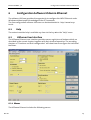
6.2.1
Menus................................................................................................29
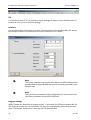
6.2.2
Buttons..............................................................................................32
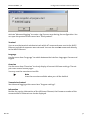
6.2.3
Status Bar..........................................................................................33
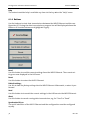
6.2.4
Tabs ...................................................................................................33
7 FUNCTIONS AND THEIR CONFIGURATION............... 34
7.1
R
EMOTE
C
ONFIGURATION VIA
T
ELNET
..........................................34
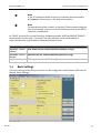
7.2
B
ASIC
S
ETTINGS
....................................................................... 35
7.2.1
Serial interface..................................................................................36
7.2.2
Handshake Configuration.................................................................36
7.2.3
Echo ...................................................................................................37
7.2.4
DTR Behavior.....................................................................................37
7.2.5
Connection........................................................................................38
7.2.6
Responses..........................................................................................38
7.2.7
Digital Inputs and Outputs ...............................................................39
7.3
N
ETWORK
/
L
EASED
L
INE
O
PERATION
..........................................39
7.3.1
IP settings..........................................................................................40
7.3.2
Input transfer (I/O tunneling)...........................................................40
7.3.3
DNS settings......................................................................................41
7.3.4
Remote maintenance........................................................................41
7.3.5
Leased line operation........................................................................42
7.4
M
ORE
F
UNCTIONS
.................................................................... 42
7.4.1
Reset / Default / Factory reset..........................................................42
7.4.2
Address allocation via network command.......................................43

Contents
Nov-06 5
7.4.3
IP block formation.............................................................................44
7.4.4
Firmware flash update......................................................................48
8 ETHERNET COM DRIVER........................................... 49
9 AT COMMAND REFERENCE ...................................... 50
10 RESPONSES AND NUMERICAL CODES ...................... 63

Introduction INSYS ETHERNET 5.X
6
Nov-06
1 Introduction
Validity range of the manual
This user manual applies to all devices of the INSYS Ethernet 5.x series.
Purpose
This manual is directed primarily at technical staff, in particular:
Programmers
Implementers
Required basics
General knowledge regarding network technologies is required. We assume that the
reader of this manual is familiar with basic general network technology terms, such as IP
address, netmask or gateway. We refer to general information sources (e.g.
www.wikipedia.com / Search for 'IP address').
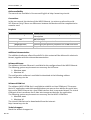
Safety Instructions
This manual includes notes which must be observed in order to avoid material damage.
The warnings and cautions are described as follows:
Caution - Damage of components!
Not observing this note may result in destruction of the device.
Warning!
Failure to comply may result in malfunction.
Note
Notes contain important information which you should observe in par-
ticular.
Warning!
The device may only be used for the cases of application provided in
the manual.

INSYS ETHERNET 5.X Introduction
Nov-06 7
Online availability
The manuals are available in German and English at http://www.insys-tec.de.
Conventions
In the user manual, the devices of the INSYS Ethernet 5.x series are referred to as IN-
SYS Ethernet. Only if there are differences between the devices will the complete device
name be used.
Emphasis
Representation
Meaning
"Basic settings" Software HSComm GUI texts, e.g. button, entry field, tab
description
AT
AT command
<expression>
Entering of the parameter for an AT command
[expression
]
Entering of the optional parameter for an AT command
OK
Response of an AT command
Additional documentation
The additional software offered from INSYS in this context will be delivered in electronic
format, together with the relevant documentation.
Software HSComm
The software HSComm Ethernet is available for the configuration of the INSYS Ethernet.
The following system requirements are necessary for HSComm:
Windows 2000
Windows XP
The configuration software is available for download at the following address:
http://www.insys-tec.de
Software VCOM Port
The software INSYS VCOM Port is available to establish a virtual COM port. This means
that a PC application under Microsoft Windows can more or less address the serial inter-
face on the INSYS Ethernet via a local COM interface that is connected ahead. The virtual
COM port driver transforms the IP data into transparent data for the application.
The following system requirements are necessary for the INSYS VCOM Port:
Windows 2000
Windows XP
The virtual COM Port can be downloaded from the Internet:
http://www.insys-tec.de
Technical support
Reach the technical support at:

Introduction INSYS ETHERNET 5.X
8
Nov-06
E-mail: [email protected]
0941/560061
Repurchasing of legacy systems
According to the new WEEE guidelines, the repurchasing and recycling of legacy systems
for our clients is regulated as follows:
Please send those legacy systems to the following address, carriage prepaid:
Frankenberg-Metalle
Gärtnersleite 8
D-96450 Coburg
This regulation applies to all devices which were delivered after August 13, 2005.

INSYS ETHERNET 5.X Overview
Nov-06 9
2 Overview
The INSYS Ethernet transparently maps a serial interface to an IP port. In connection with
the virtual COM port driver, the INSYS Ethernet can simply replace a serial cable by an
Ethernet connection in an application. Switching signals at the inputs can be transmitted
to the outputs of another module.
Fields of application
The fields of application are, for example: remote maintenance, remote monitoring, re-
mote configuration, remote switching, POS, MDE, time registration or decentralized data
collection.
Configuration
The INSYS Ethernet can be configured easily using the configuration software HSComm,
or directly via AT commands. The configuration can be performed locally at the serial
interface as well as via the network.
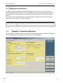
2.1 Range of Functions
Interfaces, Display and Control Elements
Mounting on DIN rail DIN EN 500 22
Power supply, 10..60 V DC, 5% ripple, terminal

Overview INSYS ETHERNET 5.X
10
Nov-06
Serial V.24/V.28 interface with 9-pin D-SUB jack and terminal
level at V24 interface according to V.28
Ethernet connection: 10Base-T on RJ45 an terminal
2 inputs, pull-up, terminal
2 switching outputs (potential-free relay), terminal
Reset key and terminal
4 LEDs for status display
Communication
Integrated TCP/UP stack for modem-compatible dialing of IP addresses or domain
names, with transparent transfer of data from and to the serial interface (“TCP
transparent”).
Protocols: ARP, ICMP, TCP/IP, UDP/IP, DHCP, DNS
Hardware handshake (RTS/CTS) and software handshake (Xon/Xoff)
Fixed speed setting
(300, 600, 1.200, 2.400, 4.800, 9.600, 19.200, 20.833, 38.400, 41.667, 57.600,
115.200)
Extended data formats for the serial interface
(8N1, 8E1, 8O1, 8N2, 7E1, 7O1, 7N2, 7E2, 7O2)
Additional functions
Extended AT command set (INSYS AT command for additional functions)
Option to configure via TELNET (remotely) or RS232 (locally)
Password protection for remote configuration
Leased line function
3 configurable TCP block formation algorithms
Firmware update of the
µ
controller (locally and remote)
Idle connection control (Data Transmit Control)
I/O tunneling, signal transfer input to output
Keep Alive function
PC configuration software HSComm Ethernet
Support for the virtual COM port driver from
INSYS MICROELECTRONICS GmbH.
Hardware watchdog

INSYS ETHERNET 5.X Overview
Nov-06 11
2.2 Device History
In the course of the stipulated switch to ROHS-compliant products (EC directive
2002/95/EG), the production of the device series INSYS Ethernet 4.x and older is ended.
The successor is the INSYS Ethernet 5.x. Besides switching to unleaded materials, this
series also utilizes a new, powerful network processor.
The INSYS Ethernet 5.1 has an additional, internal SRAM (support starts with FW V1.22-
SRAM). This is intended for further developments and has no special function at the
moment.
Version
Additional functions
V1.00 -
V1.04
Firmware porting to a new controller:
Configurable CTS polarity (for RS485)
Password-protected Telnet port
IP configuration via DHCP
(e-mail functions and autobaud are no longer supported)
V1.20
I/O tunneling (AT#IOT)
IP via ARP / ping
Leased line (AT&L<n>)
V1.21
DNS support
Baud rate via AT+IPR
V1.22
V1.22 SRAM
Max IP packet size (AT#MSS)
Individual value query
End character for packet aggregation
Software handshake

Technical Data INSYS ETHERNET 5.X
12
Nov-06
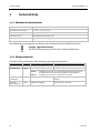
3 Technical Data
3.1.1 Mechanical characteristics
Weight
250 g
Dimensions (maximum)
w x d x h = 55 x 110 x 75
Temperature range
32°F..131°F
Protection class
Housing IP 40/ Terminal IP 20
Humidity
0 - 95% non-condensing
The following environmental conditions must be observed for the INSYS Ethernet.
Caution - Wet environment!
The INSYS Ethernet may not be used in wet environments.
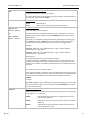
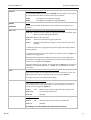
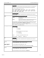
3.1.2 Display elements
The INSYS Ethernet has four LEDs to display the operational status.
Name
Color
Off
On
Power
Green
No supply voltage
Supply voltage available
No connection
Connection available or active
OH (Off Hook)
Yellow
AT&O0: OH lights up as soon as a physically functioning connection
at the Ethernet connection is available (link ok, default)
AT&O1: OH lights up as soon as a connection is active
DCD (Data Car-
rier Detect)
Green
No connection is established
Connection is established (Carrier de-
tected)
RX/TX (re-
ceive/transmit)
Green
No data exchange
Data is sent or received

INSYS ETHERNET 5.X Technical Data
Nov-06 13
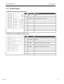
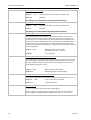
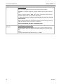
3.1.3 Terminal layout
Terminal row on the top of the cover:
Terminal
Meaning
1 GND Ground
2 X1 No function
3 10..60V DC Power supply 10V - 60V DC
4 GND Ground
5 GND Ground
6 Reset Reset input
7 GND Ground
8 Input 1 Input 1
9 Input 2 Input 2
10 GND Ground
Terminal row on the bottom of the cover:
Terminal
Meaning
11 OUT1NC Output 1 normally closed contact
12 OUT1COM
Output 1
13 OUT1NO Output 1 normally open contact
14 OUT2NC Output 2 normally closed contact
15 OUT2COM Output 2
16 OUT2NO Output 2 normally open contact
17 Rx+ Receive path
18 Rx- Receive path
19 Tx+ Send line
20 Tx- Send line

Technical Data INSYS ETHERNET 5.X
14
Nov-06
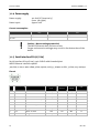
3.1.4 Power supply
Power supply: 10..60 V DC (terminal 3)
(max. 5% ripple)
Power input: approx. 2W
Current consumption
Input voltage
Current (closed cir-
cuit)
Current (connection)
Maximum startup cur-
rent
10 V DC
150 mA
150 mA
250 mA
24 V DC
70 mA
70 mA
120 mA
Caution - No overvoltage protection!
The INSYS Ethernet does not have a fuse.
Surges and excessive voltages may result in the destruction of the
device.
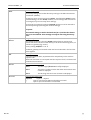
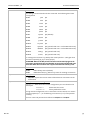
3.1.5 Serial interface RS232 (V.24)
Serial interface RS232 (V.24), 9-pin SUB-D with threaded joint.
INSYS Ethernet interface speeds:
300, 600, 1.200, 2.400, 4.800, 9.600, 19.200, 20.833, 38.400, 41.667, 57.600, 115.200 bps.
Pin-out
Pin
Description
Function
CCITT
V.24
EIA
RS232
DIN
66020
E/A DCE to
DTE
1 DCD
Data Carrier Detect
109 CF
M5
O
2 RXD
Receive Data
104 BB
D2
O
3 TXD
Transmit Data
103 BA
D1
I
4 DTR
Data Terminal Ready
108 CD
S1
I
5 GND
Ground
102 AB
E2
6 DSR
Data set ready
107 CC
M1
O
7 RTS
Request to send
105 CA
S2
I
8 CTS
Clear To Send
106 CB
M2
O
9 RI
Ring Indication
125 CE
M3
O

INSYS ETHERNET 5.X Technical Data
Nov-06 15
3.1.6 Digital inputs and outputs
Inputs and outputs can be set and queried via special AT commands. In remote configu-
ration mode (Telnet), this will enable the query of certain system states and the switch-
ing of certain system functions.
The function I/O tunneling will transmit the switching state at the inputs of the INSYS
Ethernet to the relay outputs of an additional INSYS Ethernet.
Input
The inputs (terminals 8 and 9) are designed as pull-up and are on HIGH in inactive, open
state. The alarm inputs are activated by connecting to ground.
LOW Active 0 to 1 V
HIGH Inactive 4 to 12 V
The input current from LOW to internal +5 V is typically 0.5 mA.
Switch output
The switch outputs (terminals 11 to 16) are potential-free relay switches.
Maximum switch voltage: 30 V (DC)
42 V (AC)
Maximum current load: 1 A (DC)
0.5 A (AC)
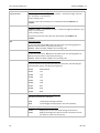
3.1.7 Ethernet interface 10Base-T
The 10Base-T Ethernet interface is designed as RJ45 as well as screw terminal. The lines
are connected internally according to the pin-out. A normal CAT5 cable must be used for
the connection to a network switch/hub.
Pin-out
Terminal
Signal
Connection to RJ45
17 Rx+
3
18 Rx-
6
19 Tx+
1
20 Tx-
2
Note
When 2 Ethernet devices are directly connected, a twisted CAT5
cable must be used.

Technical Data INSYS ETHERNET 5.X
16
Nov-06
3.1.8 Reset
Pushing the reset via the key or via the screw terminal (bridge terminal 6 with GND) is
identical.
Functions
Connection fails (1 pulse 100 ms - 500 ms for data connection)
Normal reset (continuous actuation, min. 3s)
Factory reset: (3 pulse 100 ms to 500 ms)
3.2 Certifications
The INSYS Ethernet bears the CE symbol of conformity. This symbol is a declaration that
on account of its design and implementation, the INSYS Ethernet is in compliance with
the currently valid versions of the following EC directives:
Directives: 89/336/EEC (EMC directive)
73/23/EEC (Low voltage directive)
91/263/EEC (Directive for telecommunication de-
vices)
Standards: ETS 300 342 1
EN 60950
EN 55022 (class B)
EN 55024
EN 300,607-1
EN 301 419-1
EN 3015011 V7.01
TBR 19, TBR 20
Approvals: CE

INSYS ETHERNET 5.X Initial Operation
Nov-06 17
4 Initial Operation
4.1 Scope Of Delivery
Check the scope of delivery before initial operation:
INSYS Ethernet 5.x
9-pin serial cable for the connection between the PC and the INSYS Ethernet
(RS232 cable)
Printed manual (German/English).
Optional accessories:
CD with configuration software HS Comm and manuals
Contact your supplier if the content is not complete.
Check the device for shipping damage. Please also refer to your supplier if anything is
damaged.
Keep the packaging material for dispatch or storage.
The latest edition of the manual and the configuration software are available for
download at our website: http://www.insys-tec.de.
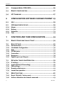
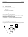
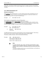
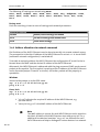
4.2 Installation Overview
The serial interface (RS232) of the INSYS Ethernet and the configuration PC (not drawn
in) are connected for initial operation and configuration.
For data communication during operation connect the terminal device with the applica-
tion (e.g. a PLC) via the serial interface with the INSYS Ethernet (see figure).
Ethernet
INSYS
Reset
Power
OH
RS-232C
10 Base-T in
Hub/Switch
RS232
Power Supply
PC

Initial Operation INSYS ETHERNET 5.X
18
Nov-06
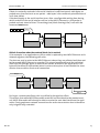
4.3 Mounting and Wiring
1. Mounting on DIN rail:
Mount the device on the DIN rail at a slight angle; to lock it into place, press the
device at the bottom.
2. Connecting the Power Supply:
Terminal layout see Chapter 3.1.3.
3. Switching the power supply on:
The power LED will light up.
4. Connecting to a network hub/switch or to another Ethernet device:
To directly connect to an additional network participant (e.g. PC) a twisted CAT5
network cable must be used.
The OH LED will light up.
5. Connection to the PC/terminal:
Insert the supplied RS 232 interface cable at the cover front and connect it to a PC
or terminal (e.g. terminal window of the configuration software HSComm or
HyperTerminal, TeraTermPro, Telix, etc.).
Set the terminal program to 19200 baud and the data format to 8N1.
6. Connection test RS232:
Perform a short test via the terminal program. Enter the command “AT” and push
the “Enter” key. When the message “OK” appears on your monitor, the RS232
connection has been successfully installed.
If the INSYS Ethernet has errors or behaves irregularly, please disconnect the power sup-
ply and the connection to the network. For those cases, please refer to your service part-
ner. To protect your guarantee claims, please do not intervene with the INSYS Ethernet.
4.4 Initial Configuration of the IP Address
At delivery, the device has no IP address (IP: 0.0.0.0). In this state, no data exchange via
the network is possible. You have the following options to set the network parameters at
the INSYS Ethernet:
• Manual IP address allocation:
o Direct input of a fixed IP address via the HSComm configuration software
o Direct input of a fixed IP address via AT command in a terminal program
o Remote configuration of a fixed IP address via ARP/PING command (see
Chapter 7.4.2)
• Automatic IP address allocation:
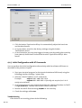
o DHCP activation via AT command in a terminal program
o DHCP activation via HSComm configuration software
You may need to contact the responsible person for the IP network to clarify which kind
of address allocation must be used.

INSYS ETHERNET 5.X Initial Operation
Nov-06 19
Only with a correctly set network interface will the full range of functions be available.
Besides data connections, also remote configuration or remote updates via Telnet will be
available.
4.4.1 Brief introduction to IP
IP address and netmask
The IP address of a network device is a 32 bit numerical value for the detection of an in-
dividual device within a network and is in general displayed as 4 decimal numbers be-
tween 0 and 255, which are separated by full stops.
Example: IP 192.168.100.210
The IP address is composed of 2 pieces of information:
The network code and the device number within this network.
The NetMask (NM) defines which 4 digits belong to the network code and which to the
device number. All digits which are allocated 255 in the NM belong to the network code.
In most networks, the NM is set up as shown in the following example.
Example: IP 192.168.100.210
NM 255.255.255.0
Network 192.168.100.
Device 210
The NM should be the same for all participants of a local network segment. This also ap-
plies to the first part of the IP address which indicates the network code.
The device number, however, must be allocated individually.
Example: NM 255.255.255.0
Device A 192.168.100.210
Device B 192.168.100.211
Device C 192.168.100.212
Note
In private networks, only certain, specially reserved address ranges
should be used as network codes (e.g. 192.168.xxx.xxx) to avoid any
possible address conflicts in connection with the Internet from the be-
ginning.
The device numbers 0 and 255 are reserved addresses and should not
be used as subscriber addresses.

Initial Operation INSYS ETHERNET 5.X
20
Nov-06
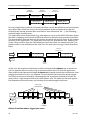
Gateway and routing
If data must be sent beyond the limits of a local network to a destination in another
segment (different network code), a Gateway (GW) must be defined via a gateway ad-
dress, which is located within the local network segment. A gateway is a device with two
network interfaces which acts as an exchange station between the network segments.
If a device detects that the destination address is not located in the own, local segment
(comparison of the own IP with the destination IP via NM), the packet is instead sent to
the GW. The GW will route the packet accordingly, i.e. will send it to the second network
segment connected to the GW.
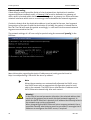
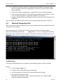
The network settings of a PC can easily be queried using the command 'ipconfig' in the
DOS box:
More information regarding the topics IP addresses and routing can be found at
http://en.wikipedia.org/ Search for the term 'ip address'.
Note
When the parameters are automatically allocated via DHCP, an ac-
tive DHCP server with an appropriate configuration must be avail-
able in the network. The DHCP server allocates the IP address to the
INSYS Ethernet automatically after each restart.
Warning!
In the case of manual parameter allocation, the selected address, Net-
mask and the gateway must match the local network segment, in
which the INSYS Ethernet is located. An IP address that already exists in
the network may not be re-allocated!
When integrating the INSYS Ethernet into a company network, the re-
sponsible network administrator must be consulted. It manages the IP
addresses or configures the DHCP server, if required.
Page is loading ...
Page is loading ...
Page is loading ...
Page is loading ...
Page is loading ...
Page is loading ...
Page is loading ...
Page is loading ...
Page is loading ...
Page is loading ...
Page is loading ...
Page is loading ...
Page is loading ...
Page is loading ...
Page is loading ...
Page is loading ...
Page is loading ...
Page is loading ...
Page is loading ...
Page is loading ...
Page is loading ...
Page is loading ...
Page is loading ...
Page is loading ...
Page is loading ...
Page is loading ...
Page is loading ...
Page is loading ...
Page is loading ...
Page is loading ...
Page is loading ...
Page is loading ...
Page is loading ...
Page is loading ...
Page is loading ...
Page is loading ...
Page is loading ...
Page is loading ...
Page is loading ...
Page is loading ...
Page is loading ...
Page is loading ...
Page is loading ...
Page is loading ...
-
 1
1
-
 2
2
-
 3
3
-
 4
4
-
 5
5
-
 6
6
-
 7
7
-
 8
8
-
 9
9
-
 10
10
-
 11
11
-
 12
12
-
 13
13
-
 14
14
-
 15
15
-
 16
16
-
 17
17
-
 18
18
-
 19
19
-
 20
20
-
 21
21
-
 22
22
-
 23
23
-
 24
24
-
 25
25
-
 26
26
-
 27
27
-
 28
28
-
 29
29
-
 30
30
-
 31
31
-
 32
32
-
 33
33
-
 34
34
-
 35
35
-
 36
36
-
 37
37
-
 38
38
-
 39
39
-
 40
40
-
 41
41
-
 42
42
-
 43
43
-
 44
44
-
 45
45
-
 46
46
-
 47
47
-
 48
48
-
 49
49
-
 50
50
-
 51
51
-
 52
52
-
 53
53
-
 54
54
-
 55
55
-
 56
56
-
 57
57
-
 58
58
-
 59
59
-
 60
60
-
 61
61
-
 62
62
-
 63
63
-
 64
64


Insys 11-02-01-05-00.010 Datasheet
- Category
- Networking
- Type
- Datasheet
Ask a question and I''ll find the answer in the document
Finding information in a document is now easier with AI
Related papers
-
Insys Modem 56k 4.2 Owner's manual
-
-
-
-
-
-
-
-
-
Other documents
-
Kärcher RDS1 SB-C SB-M Owner's manual
-
SICK MPR Meeting Point Router Operating instructions
-
Eneo VTD-1 Operating Instructions Manual
-
 BAB TECHNOLOGIE EIBPORT V3 Firmware Update Procedure
-
 GalileoSky gps light User manual
-
Datalogic Scanning SC6000 User manual
-
Toshiba IPR16-X User manual
-
Allnet ALL3090 Owner's manual
-
AUDAC APC100 MK2 User manual
-
Hirschmann BAT-C Reference guide

