Page is loading ...

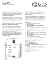
INTRODUCTION
The DygiZone 4 zone security lighting controller works in
conjunction with GJD’s 4 Zone Expansion Unit and range
of external detectors.
PACKAGE CONTENTS
1 x DygiZone 4 zone security lighting controller
2 x xing screws
2 x wall plugs
1 x installation guide
POWERING UP THE DYGIZONE
After powering up the DygiZone controller with the battery
removed:
• Each zone’s status LEDs (red, yellow and green)
and blue zone buttons will ash
• All LCDs icons will display on the screen
When installation is completed removing the backup
battery tab will enable the clock to keep running in the
event of power loss
NOTE: Press any button to clear the display.
Alternatively, the display will clear automatically after
1 minute.
When the display clears, and if nothing is activated:
• The LCD displays the clock time (automatically
defaults to 00:00 if the battery is not connected)
• The symbol M appears on the DygiZone which is
congured as the master controller.
Note: The letter M does not appear when setting up a
DygiZone as a slave controller.
• Each zone’s status LEDs will display the zone’s
current programme state.
Note: The factory default setting is audible and
automatic for all active zones (red and green status
LEDs illuminated).
ZONE INDICATOR ICONS
For each of the 4 zones there are a set of sub-zone icons
that appear above the respective zone’s status LEDs.
Note: These icons will not be displayed until a detector
on the system has triggered.
When a detector connected to the A1, A2 or A3 input of the
Expansion Unit is triggered:
• The LCD will display the numbers 1,2 and 3 above
the respective zone number.
• A circle will appear around the number that
corresponds to the detector that has been triggered.
• The corresponding zone’s button will illuminate.
Note: The numbers 1, 2 and 3 correspond to the
Expansion unit inputs A1, A2 and A3 respectively.
Upon activation the circle will ash for 8 seconds and then
will remain visible for a time duration equal to the setting
of TIME MINS in the engineer programming. The numbers
1, 2 and 3 will also be visible for this time but will not ash.
Once this time has elapsed, all the icons will clear from the
LCD.
ZONE MODES & STATUS INDICATORS
Audible Mode: Beep or voice mode is activated and will
sound on detector activation.
Status Icon: Musical note icon for either voice
or beep more. The microphone icon is only
visible if voice mode is selected.
Status LED: Red, constantly lit.
Automatic Mode: Works in conjunction with the photocells
in the detectors. The external security lights will only be
activated if it is dark, thereby saving energy.
Status Icon: Stick gure icon
Status LED: Green, constantly lit LED
indicates mode selected.
Yellow LED illuminates when the external
lighting is activated.
Manual Override Mode: The external security light will
now remain on irrespective of detector status - useful for
barbecues or when working outside in the dark for long
periods.
Status Icon: Light bulb icon
Status LED: Yellow, lit during light activation
period.
Time Mode: External security lights will be illuminated as
per the TIME 1 or Timer 2 options.
Status Icon: Light bulb icon
Status LED: Yellow, lit during light activation
period.
Note: Zone status icons are only visible when the
respective zone button is pushed. The icons are
located in the top-centre of the LCD display.
INDIVIDUALLY SETTING ZONES
Each zone can be individually congured from the keypad
by cycling through the available modes.
The conguration process is as follows:
• Press the button for zone you would like to congure.
The zone’s status LEDs and icons will be displayed.
• Press the button again to cycle through the different
modes available until the desired mode is reached.
DygiZone
GJD910 4 Zone Security Lighting Controller
Detect.Illuminate.Dete
r

The modes appear in the following sequence:
• Audible & Automatic mode selected (Factory default)
• Automatic mode only selected
• Audible mode only selected
• Zone disabled
• Manual Override mode selected
Note: Sequence begins at the currently selected
mode and will repeat.
DETECTION INFORMATION DISPLAY
LED Information and Text
• PIR text will ash for approximately 8 seconds for
that zone
• The blue LCD back-light will come on for about 6
seconds during the trigger state and will remain on
for approximately 6 seconds after the trigger has
occurred.
• The text will display for a time duration equal to the
setting of TIME MINS in the engineer programming.
Note: If another PIR activation occurs on any other
zone then the text will be displayed for that new zone
for the same pre-programmed time on duration.
RECORDING A VOICE MESSAGE
1. Press and hold the red button until the microphone
symbol appears on the LCD.
2. Press the required zone button once and then
release. As you release the zone button a horizontal
bar with ten segments will appear below the
microphone symbol on the LCD. This indicates the
amount of recording time available where each
segment is equivalent to one second. Therefore, a
ten second message can be recorded.
3. Speak into the microphone on the front cover of the
DygiZone to indicate location ( e.g. patio area, front
door, side garden, etc)
4. When you have nished speaking into the
microphone quickly press the zone button again
(there will be no audible beep)
5. The recorded message will now automatically play
back. If you are satised with the message then do
nothing. If you wish to re-record the message then
repeat steps 1 to 5. You now need to set-up the
recorded message for the appropriate zone.
6. Press and hold down the red button until the
microphone symbol appears in the LCD and then
release.
7. Now press and continue to hold down the zone
button for which the voice message is to apply until
an audible beep is heard. Release the zone button
and the programming has been completed.
The voice message mode can be conrmed by pressing
the zone button once. A microphone symbol will appear on
the LCD if audible mode has been pre-selected.
Note 1: The normal default status for sensor activation
is an audible beep (i.e. one beep for zone 1, two beeps
for zone 2, etc.)
Note 2: It is possible to mix both audible beeps and
recorded messages (e.g. zone 1 could be in beep and
zone 2 could be in recorded voice playback.)
To change from a voice message to a beep, repeat steps
6 & 7.
ENGINEER PROGRAMMING
Whichever zone requires adjustment, press and hold down
that zone button until the programming options show on the
LCD display.
Use the red button to cycle through the available options
until the one to be adjusted is reached. The settings for
that option can then be adjusted by using the up button.
Once the required setting is obtained, press the red button
to conrm it. Repeat the above process until all changes
have been completed then press any Zone button to exit
programming.
If buttons are pressed for 30 seconds the DygiZone will
automatically exit the programming mode.
SELECTING NUMBER OF ACTIVE ZONES
1. Press and hold down the zone 1 button, this will enter
programming mode.
2. The zone number will already be selected and can be
changed using the up button
3. Press the red button to conrm the number of zones
Notes: Unused zones will be cleared (i.e. no LCD
information will be displayed and there will be no
illuminated LEDs). An audible beep will be heard if any of
the unused zone buttons are pressed, but no action will be
taken.
4. Press zone 1 button to exit the programming mode.
SETTING TIME ON FOR LIGHTS
When a detector on a zone set to the automatic mode
(green led) is triggered during the hours of darkness, the
lights for that zone will activate. The lights will stay active
for a time duration equal to the setting of TIME MIS in the
engineer programming. This time can be set to 1, 2, 3, 4,
5, 8, 12, 16 or 24 minutes using the red and up buttons.
Once the desired value is set, simply press any of the zone
buttons to exit the engineer programming.

SETTING DETECTOR SENSITIVITY (Pulse
Count)
The number of times a detector must trigger (pulse count)
before the DygiZone reacts is selected by adjusting the
setting of PULSE in the engineer programming. This can
be set at 1, 2 or 3 using the red and up buttons. Once the
desired value is set, simply press any of the zone buttons
to exit the engineer programming.
Note: When using a DygiZone with GJD detectors
where the pulse count is set on the detector itself,
ensure that the detector pulse count is set to 1. This
will apply to D-TECT, ELITE, and Opal RFX detectors,
but does not apply to the Opal XL detector.
MODE SETTINGS
One of ve modes can be programmed for each zone.
Mode 1 - 24hr = Lights operate day and night with
detection when auto is selected
Mode 2 - Link (Zone 1) = Detectors on zone 1 also
activate lights on zone 2 when auto is selected
Mode 2 - Link (Zone 2) = Detectors on zone 2 also
activate lightings on zone 1 when auto is selected
Mode 2 - Link (Zone 3) = Detectors on zone 3 also activate
lights on zone 4 when auto is selected
Mode 2 - Link (Zone 4) = Detectors on zone 4 also activate
lights on zone 3 when auto is selected
Mode 3 - 24+L = Outside light will operate day and night
with detection according to the Link settings above
Mode 4 -STD = Outside lights will only operate at night
with detection. Detectors on that zone will only operate that
zone.
Mode 5 - ALL = All lights on all zones that have Mode 5
selected are activated at night with detection from any zone
with Mode 5 selected. Any zones with ALL selected will be
treated as a group.
TSEC OUTPUT
When using the audible output mode, the T output on the
GJD Expansion Unit will provide a 12 V positive switched
signal for a time duration equal to the setting of TSEC in
the engineer programming. This can be set at 1, 5, 10,
20 or 30 seconds using the red and up buttons. Once the
desired value is set, simply press any of the zone buttons
to exit the engineer programming.
SETTING THE CLOCK DISPLAY
The clock display format can be adjusted using the CLOCK
setting in the engineer programming. It can be set to 12,
24 or OFF using the red and up buttons. Once the desired
setting is reached, simply press any of the zone buttons to
exit the engineer programming.
Note 1: AM and PM symbols will appear beside the
displayed time accordingly when 12 hr format is
selected
Note 2: Any zone times being used will display the time
in the selected format.
SETTING THE CLOCK
The LCD clock is set using the UP and RED buttons in the
engineer programming. The clock format must rst be set
to 24hr mode then the following method is used:
1. Press and hold down any zone button until the
engineer programming is displayed
2. Press the red button six times and the hour digits will
begin to ash.
3. Set the hours by using the up button then press the
red button.
4. The minute digits will now begin to ash. Set the
minutes using the UP button then press the red
button
5. Exit the engineer programming pressing any of the
zone buttons. The time will now display on the LCD
clock.
Note: If the power is removed for more than a few
hours, the clock display will be reset to 00:00. All other
devices setting will remain as they were prior to power
down.
WALK TEST
Walk test mode has to be selected for each zone that
is being walk tested. In this mode, as each detector is
activated, the audible beep will sound & the relevant zone
& PIR number is displayed on the LCD.
The external lights connected to that zone will turn on for
4 seconds each time a beam is crossed. Each zone has to
be tested individually.
Walk test can be selected using the following method:
1. Hold down the button for zone you wish to test until
the engineer programming appears
2. Press the red button 8 times so that a ashing hand
icon is visible
3. Press the up button to select walk test mode
The zone button will begin to ash and the red and green
LEDs for that zone will illuminate.
To exit walk test mode press the red button once.
Alternatively, the DygiZone will automatically cancel the
walk test more 5 minutes after the last trigger.
PRE-SET LIGHT ON/OFF TIMES FOR
INDIVIDUAL ZONES
Each zone can be programmed to automatically switch the
external lights on & off at pre set times, The on & off times
must be in the same day as each other (i.e. they must not
cross 00:00). Each zone has two programmable times (T1
& T2) which are set using the following method:
1. Hold the button for the zone you wish to set the
timers for until the engineer programming appears.
2. Press the red button 9 times so that the clock hours
are ashing and T1 ON is displayed
3. Set the hours by using the up button then press the
red button

PRE-SET LIGHT ON/OFF TIMES FOR
INDIVIDUAL ZONES
1. The minute digits will now begin to ash. Set the
minutes using the up button then press the red
button.
2. Repeat steps 3 & 4 for the T1 OFF time and again for
the T2 ON & OFF times if required.
3. Press any zone button to exit the programming.
Note: If the times are not required, they should both be
set to 01:00 for on and off times (default setting).
LOCKING THE KEY PAD
Locking the key pad prevents accidental programme or
setting changes.
To lock - press and hold down zone buttons 1 and 4 at the
same time: a single beep will be heard and the spanner
symbol on the keypad will ash to conrm that the key pad
is locked.
To unlock - repeat the action and two beeps will be heard.
and the spanner symbol will disappear.
DEFAULT SETTINGS
To return the DygiZone to its default settings:
1. Press and hold down any zone button until the
engineer programming is displayed.
2. Press the red button 16 times so that DEFAULT is
ashing.
3. Press the up button to rest the default settings.
The default settings are:
• Zones active = 4
• Light on time = 1 minute
• Pulse count = 1
• T seconds = 5
• Clock mode = 24hr
• Mode = 4
POWER UP RESET
This would normally be initiated by a qualied electrician or
security systems installer.
To reset the DygiZone, remove the backup battery and
power and then while holding zone buttons 1 & 4. re-apply
the power.
The clock will be reset and the programming will revert
to default setting. All the zones will be set to audible and
auto modes ( i.e. the red and green LEDs will be lit on all
4 zones).
Note: After a full systems reset, any detectors
connected to the GJD expansion unit will not activate
for 2 to 3 minutes.
DYGIZONE SLAVE CONTROLLERS (Optional)
Up to four additional DygiZone controllers can be
connected to the system, additional Expansion Units
or power supplies may be required to provide the 12 V
supply. Only the Master controller can be used to set the
programme options, but different voice messages can
be recorded on the remotely located Slave controllers.
The keypad can also be locked on the Slave controllers
otherwise the slaves will mimic the Master.
Changing a button selection on the Master DygiZone will
instantly change the settings on the Slave controllers.
Changing a button selection on any of the Slave controllers
will instantly change the setting on that Slave and Master,
the settings on other Slaves will change within one minute.
It is recommended that the DygiZone which will be used
the most should be congured as the Master.
MAINTENANCE MODE
The spanner icon ashes when the keypad is locked and is
steady when the supply voltage to the DygiZone is outside
the specication (i.e. below 9 V or more than 14 V. )
IMPORTANT: If the keypad is not locked and the
spanner icon is showing steady, please call a
maintenance engineer.
Supply 12 V DC @ 20 mA standby,
100 mA triggered with
messages
Display Blue back-lit LCD display
showing real time clock,
detector activation and zone
status
Back-lit LCD brightness can
be adjusted using the trim pot.
Engineer adjustment only.
Audible Internal warning tine with
individual tones for each zone
or selectable 10 second voice
recordable messages for each
zone.
Internal speaker volume can
be adjusted using the trim pot.
Engineer adjustment only
Control Four individual zone buttons
for selecting zone status and
programming options
System
Conguration
Normally 1 Master and 1 Slave
DygiZone. Additional Slaves
can be added if required.
Requires GJD Expansion
Units.
Timer Control Two individual on/off times
per zone
Mounting Indoor use only. Mount ina
clean dry location. Can be
mounted on a standard single
or double ush back box.
Temperature -10º C to +55ºC
Dimensions 134 W x 87 H x 30D
Weight 190g NET, 260g GROSS
Certications


4 ZONE EXPANSION UNIT WIRING DIAGRAM


Unit 2, Birch Business Park, Whittle Lane, Heywood, Greater Manchester, OL10 2SX, UK
w: www.gjd.co.uk t: +44 (0) 1706 363 998 f: +44 (0) 1706 363 991
ENGINEER NOTES
/