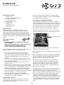
GJD GJD260 is a highly sophisticated, IP-based motion detection device and alarm trigger that combines the power of IP with PoE (Power over Ethernet), advanced signal processing, quad pyro scanning and unique optical systems combined with microwave detection to provide state-of-the-art alarm capture. The ability to connect the device using standard CAT5 cable and PoE makes installation easy and convenient. The multifunction lens fitted to this model produces seven long range beams and seven medium to short range curtain PIR beams, providing wide coverage and detection capabilities. The PIR circuitry detects changes in heat and movement in the beam pattern, making it ideal for detecting intruders or other activities in the monitored area.
GJD GJD260 is a highly sophisticated, IP-based motion detection device and alarm trigger that combines the power of IP with PoE (Power over Ethernet), advanced signal processing, quad pyro scanning and unique optical systems combined with microwave detection to provide state-of-the-art alarm capture. The ability to connect the device using standard CAT5 cable and PoE makes installation easy and convenient. The multifunction lens fitted to this model produces seven long range beams and seven medium to short range curtain PIR beams, providing wide coverage and detection capabilities. The PIR circuitry detects changes in heat and movement in the beam pattern, making it ideal for detecting intruders or other activities in the monitored area.


-
 1
1
-
 2
2
-
 3
3
-
 4
4
-
 5
5
-
 6
6
-
 7
7
-
 8
8
-
 9
9
-
 10
10
-
 11
11


GJD GJD260 is a highly sophisticated, IP-based motion detection device and alarm trigger that combines the power of IP with PoE (Power over Ethernet), advanced signal processing, quad pyro scanning and unique optical systems combined with microwave detection to provide state-of-the-art alarm capture. The ability to connect the device using standard CAT5 cable and PoE makes installation easy and convenient. The multifunction lens fitted to this model produces seven long range beams and seven medium to short range curtain PIR beams, providing wide coverage and detection capabilities. The PIR circuitry detects changes in heat and movement in the beam pattern, making it ideal for detecting intruders or other activities in the monitored area.
Ask a question and I''ll find the answer in the document
Finding information in a document is now easier with AI
Related papers


Other documents
-
DirekTronik 20109790 Owner's manual
-
 Digital Watchdog DW-DTMWIPW, DW-DTPIRIPW User manual
-
Potter PIR-TECT 2 Dual Technology External Motion Detector Owner's manual
-
Eaton DET-REXT-PIR30 Installation guide
-
Electronics Line iconnect Installation guide
-
Fracarro 910335 Datasheet
-
Ironman Fitness V2 User manual
-
PARADOX ENVY NVX80 Reference And Installation Manual
-
Ness Quantum R12 Radio PIR Installation Notes
-
Risco LightSYS 2 Series Installation And Programming Manual
