Page is loading ...

PositionServo with MVOB
Users Manual
Valid for Hardware Version 2

Copyright ©2010 by Lenze AC Tech Corporation.
All rights reserved. No part of this manual may be reproduced or transmitted in any form without written
permission from Lenze AC Tech Corporation. The information and technical data in this manual are
subject to change without notice. Lenze AC Tech makes no warranty of any kind with respect to this
material, including, but not limited to, the implied warranties of its merchantability and fitness for a given
purpose. Lenze AC Tech assumes no responsibility for any errors that may appear in this manual and
makes no commitment to update or to keep current the information in this manual.
MotionView®, PositionServo®, and all related indicia are either registered trademarks or trademarks
of Lenze AG in the United States and other countries.
Windows™ and all related indicia are registered trademarks of Microsoft Corporation.
Java™ and all related indicia are registered trademarks of Sun Microsystems, Incorporated.
CANopen® is a registered trademark of ‘CAN in Automation (CiA)’.
DeviceNet™, EtherNet/IP™, and all related indicia are trademarks of ODVA (Open Device Vendors
Association).
PROFIBUS DP™ is a registered trademark of PROFIBUS International.
This document printed in the United States of America.

S94H201D 1
Contents
1 Introduction......................................................................5
1.1 Safety Information ...........................................................5
1.2 Legal Regulations............................................................5
1.3 General Drive Information...................................................... 6
1.3.1 Mains Configuration ...................................................6
1.3.2 Operating Modes......................................................6
1.3.3 Feedback ...........................................................7
1.3.4 Software............................................................7
1.4 Part Number Designation ......................................................8
1.4.1 Drive Part Number..................................................... 8
1.4.2 Filter Part Number..................................................... 8
1.4.3 Option Part Number.................................................... 9
2 Technical Data ..................................................................10
2.1 Electrical Characteristics .....................................................10
2.2 Power Ratings .............................................................11
2.3 Fuse Recommendations......................................................12
2.4 Digital and Analog I/O Ratings .................................................12
2.5 Environment...............................................................12
2.6 Operating Modes ........................................................... 12
2.7 Connections and I/O......................................................... 13
2.8 PositionServo Dimensions ....................................................14
2.9 Clearance for Cooling Air Circulation. . . . . . . . . . . . . . . . . . . . . . . . . . . . . . . . . . . . . . . . . . . . . 15
3 Installation .....................................................................16
3.1 Wiring ...................................................................17
3.2 Shielding and Grounding .....................................................17
3.2.1 General Guidelines ................................................... 17
3.2.2 EMI Protection.......................................................18
3.2.3 Enclosure ..........................................................18
3.3 Line Filtering .............................................................. 18
3.4 Heat Sinking............................................................... 19
3.5 Line (Mains) Fusing ......................................................... 19
4 Interface.......................................................................20
4.1 External Connectors.........................................................20
4.1.1 P1 & P7 - Input Power and Output Power Connections . . . . . . . . . . . . . . . . . . . . . . . . 20
4.1.2 P2 - Ethernet Communications Port. . . . . . . . . . . . . . . . . . . . . . . . . . . . . . . . . . . . . . . 21
4.1.3 P3 - Controller I/O....................................................22
4.1.4 P4 - Motor Feedback..................................................23
4.1.5 P5 - 24 VDC Back-up Power Input. . . . . . . . . . . . . . . . . . . . . . . . . . . . . . . . . . . . . . . . 24
4.1.6 P6 - Braking Resistor and DC Bus . . . . . . . . . . . . . . . . . . . . . . . . . . . . . . . . . . . . . . . . 24
4.1.7 Connector and Wiring Notes ............................................ 25
4.1.8 P8 - ISO 13849-1 Safety Circuit (option) . . . . . . . . . . . . . . . . . . . . . . . . . . . . . . . . . . . 26
4.2 Digital I/O Details ...........................................................31
4.2.1 Step & Direction/Master Encoder Inputs (P3, pins 1-4) . . . . . . . . . . . . . . . . . . . . . . . . 31
4.2.2 Buffered Encoder Output (P3, pins 7-12) . . . . . . . . . . . . . . . . . . . . . . . . . . . . . . . . . . . 32
4.2.3 Digital Outputs ......................................................32
4.2.4 Digital Inputs........................................................ 33
4.3 Analog I/O Details...........................................................34
4.3.1 Analog Reference Input................................................ 34
4.3.2 Analog Output....................................................... 35
4.4 Communication Interfaces ....................................................35
4.4.1 Ethernet Interface (standard)............................................35
4.4.2 RS485 Interface (option) ...............................................35
4.4.3 Modbus RTU Support .................................................36
4.4.4 CANopen Interface ...................................................36
4.4.5 DeviceNet Interface................................................... 36
4.4.6 PROFIBUS DP Interface ................................................ 37
4.5 Motor Selection ............................................................ 37
4.5.1 Motor Connection .................................................... 37
4.5.2 Motor Over-Temperature Protection . . . . . . . . . . . . . . . . . . . . . . . . . . . . . . . . . . . . . . 37

2 S94H201D
Contents
5 Parameters.....................................................................38
5.1 Drive Identification..........................................................39
5.1.1 Drive Name......................................................... 39
5.1.2 Group ID ........................................................... 39
5.2 Motor....................................................................40
5.2.1 Motor Setup ........................................................ 40
5.2.2 Using a Custom Motor................................................. 41
5.2.3 Creating Custom Motor Parameters. . . . . . . . . . . . . . . . . . . . . . . . . . . . . . . . . . . . . . . 41
5.2.4 Autophasing ........................................................42
5.2.5 Custom Motor Data Entry ..............................................43
5.3 Parameters ...............................................................47
5.3.1 Drive Mode . . . . . . . . . . . . . . . . . . . . . . . . . . . . . . . . . . . . . . . . . . . . . . . . . . . . . . . . . 48
5.3.2 Reference..........................................................48
5.3.3 Drive PWM Frequency................................................. 49
5.3.4 Current Limit........................................................49
5.3.5 To Change Current Limits ..............................................49
5.3.6 Peak Current Limit (8 kHz and 16 kHz) . . . . . . . . . . . . . . . . . . . . . . . . . . . . . . . . . . . . 49
5.3.7 Accel/Decel Limits (velocity mode only). . . . . . . . . . . . . . . . . . . . . . . . . . . . . . . . . . . . 49
5.3.8 Fault Reset .........................................................49
5.3.9 Motor Temperature Sensor ............................................. 50
5.3.10 Motor PTC Cutoff Resistance............................................ 50
5.3.11 Regen Duty Cycle .................................................... 50
5.3.12 Master Encoder Input Type (position mode only) . . . . . . . . . . . . . . . . . . . . . . . . . . . . . 51
5.3.13 Master Encoder - System to Master Ratio . . . . . . . . . . . . . . . . . . . . . . . . . . . . . . . . . . 51
5.3.14 Autoboot...........................................................51
5.3.15 User Units..........................................................51
5.3.16 Rotation Direction .................................................... 51
5.3.17 Resolver Tracks......................................................51
5.4 Communication ............................................................ 52
5.4.1 Ethernet ...........................................................52
5.4.2 RS-485............................................................52
5.4.3 CAN ..............................................................52
5.4.4 PROFIBUS..........................................................52
5.5 Analog I/O ................................................................53
5.5.1 Analog Output....................................................... 53
5.5.2 Analog Output Current Scale (Volt/Amps). . . . . . . . . . . . . . . . . . . . . . . . . . . . . . . . . . . 53
5.5.3 Analog Output Velocity Scale (mV/RPM). . . . . . . . . . . . . . . . . . . . . . . . . . . . . . . . . . . . 53
5.5.4 Analog Input Current Scale (Amps/Volt) . . . . . . . . . . . . . . . . . . . . . . . . . . . . . . . . . . . . 53
5.5.5 Analog Input Velocity Scale (RPM/Volt). . . . . . . . . . . . . . . . . . . . . . . . . . . . . . . . . . . . . 53
5.5.6 Analog Input Dead Band ...............................................54
5.5.7 Analog Input Offset ...................................................54
5.6 Digital I/O................................................................. 54
5.6.1 Digital Output ....................................................... 54
5.6.2 Digital Input De-bounce Time ........................................... 54
5.6.3 Hard Limit Switch Action...............................................54
5.6.4 Enable Switch Function................................................ 54
5.6.5 Brake Release Delay..................................................55
5.7 Velocity Limits ............................................................. 55
5.7.1 Zero Speed . . . . . . . . . . . . . . . . . . . . . . . . . . . . . . . . . . . . . . . . . . . . . . . . . . . . . . . . . 55
5.7.2 Speed Window ...................................................... 55
5.7.3 At Speed........................................................... 55
5.8 Position Limits ............................................................. 56
5.8.1 Position Error .......................................................56
5.8.2 Max Error Time......................................................56
5.8.3 Soft Limits.......................................................... 56

S94H201D 3
Contents
5.9 Compensation .............................................................56
5.9.1 Velocity P-gain (proportional)............................................ 56
5.9.2 Velocity I-gain (integral)................................................56
5.9.3 Position P-gain (proportional) ...........................................57
5.9.4 Position I-gain (integral) ...............................................57
5.9.5 Position D-gain (differential) ............................................57
5.9.6 Position I-limit....................................................... 57
5.9.7 Gain Scaling Window.................................................. 57
5.9.8 Disable High Performance Mode . . . . . . . . . . . . . . . . . . . . . . . . . . . . . . . . . . . . . . . . . 57
5.9.9 Auto Tuning.........................................................57
5.9.10 Set Default Gains.....................................................58
5.9.11 Feedback and Loop Filters..............................................58
5.10 Tools .................................................................... 59
5.10.1 Oscilloscope ........................................................59
5.10.2 Parameter & I/O View ................................................. 60
5.11 Faults.................................................................... 61
5.12 Monitor ..................................................................62
6 Operation ...................................................................... 63
6.1 Minimum Connections .......................................................63
6.2 Ethernet Connection......................................................... 63
6.2.1 PositionServo Ethernet Port Configuration . . . . . . . . . . . . . . . . . . . . . . . . . . . . . . . . . . 64
6.2.2 Configuring the PC IP Address (Windows XP) . . . . . . . . . . . . . . . . . . . . . . . . . . . . . . . . 66
6.2.3 Initial Connection to the Drive ...........................................69
6.2.4 Launching MotionView & Communicating to the PS Drive . . . . . . . . . . . . . . . . . . . . . . 70
6.3 Parameter Storage and EPM Operation. . . . . . . . . . . . . . . . . . . . . . . . . . . . . . . . . . . . . . . . . . . 73
6.3.1 Parameter Storage ................................................... 73
6.3.2 EPM Operation ...................................................... 73
6.3.3 EPM Fault .......................................................... 73
6.4 Configuration of the PositionServo ..............................................74
6.5 Position Mode Operation (gearing) ..............................................75
6.6 Enabling the PositionServo.................................................... 75
6.7 Drive Tuning............................................................... 76
6.7.1 Auto Tuning the Drive .................................................76
6.7.2 Manually Tuning the Drive in Velocity Mode. . . . . . . . . . . . . . . . . . . . . . . . . . . . . . . . . 77
6.7.3 Manually Tuning the Drive in Position Mode . . . . . . . . . . . . . . . . . . . . . . . . . . . . . . . . 82
6.8 Upgrading Firmware.........................................................87
7 Quick Start Reference............................................................. 88
7.1 Quick Start - External Torque Mode ............................................. 88
7.2 Quick Start - External Velocity Mode.............................................89
7.3 Quick Start - External Positioning Mode . . . . . . . . . . . . . . . . . . . . . . . . . . . . . . . . . . . . . . . . . . 91
8 Diagnostics.....................................................................93
8.1 Diagnostic Display ..........................................................93
8.2 Diagnostic LEDs............................................................ 94
8.3 Stop/Reset................................................................94
8.4 Faults.................................................................... 95
8.4.1 Fault Codes.........................................................95
8.4.2 Fault Event .........................................................97
8.4.3 Fault Reset .........................................................97
8.4 Troubleshooting............................................................97

4 S94H201D
About These Instructions
This documentation pertains to the PositionServo drive with Hardware Version 2. This documentation contains
important technical data regarding the installation, operation and commissioning of the drive. Observe all
safety instructions. Read this document in its entirety before operating or servicing a PositionServo drive.
Drive Hardware Version
For hardware version 2, the drive dataplate (identification label) displays “2” in the fourth to last digit of the
drive indentification number. Refer to “E” designation in the drive identification label. Upon power-up the
drive LED display will read “9402” to indicate 940 PositionServo, hardware version 2.
If upon power-up the drive LED reads “940”, the drive has hardware version 1. Refer to User Manual
S94PM01 for hardware version 1 drives.
Drive Identification Label
C A B D E F
Type:
E94P120Y2NES
ID-No: 13014745
INPUT: 1(3)/PE
120/240 V
24.0 (13.9) A
50-60 HZ
OUTPUT: 3/PE
0 - 230 V
12.0 A
For detailed information
refer to instruction
Manual: S94H201
SN 13014745012345678
E94P120Y2NES0XX2# ##
Made in USA
Model 940
13014745012345678
A B C D E F
Certifications Model
Number
Input
Ratings
Output
Ratings
Hardware
Version
Software
Version
Package Contents
Scope of Supply Important
1 Model PositionServo:
Type E94P or E94R
1 Mounting Instructions (English)
1 MotionView CD ROM including:
- configuration software
- documentation
After reception of the delivery, immediately check whether the scope
of supply matches the accompanying papers. Lenze- AC Tech does
not accept any liability for deficiencies claimed subsequently.
Claim:
- visible transport damage immediately to the forwarder
- visible deficiencies / incompleteness immediately to your Lenze
representative.
Related Documents
The documentation listed herein contains information relevant to the operation of the PositionServo and
MotionView OnBoard. To obtain the latest documentation, visit the Technical Library at http://www.
lenzeamericas.com.
Table 1: Reference Documentation
Document # Description
P94MI01 PositionServo (with MVOB) Mounting Instructions
PM94H201 PositionServo (with MVOB) Programming Manual
P94MOD01 Position Servo ModBus RTU over RS485 ; Modbus TCP/IP
P94CAN01 PositionServo CANopen Communications Reference Guide
P94DVN01 PositionServo DeviceNet Communications Reference Guide
P94ETH01 PositionServo EtherNet/IP Communications Reference Guide
P94PFB01 PositionServo PROFIBUS Communications Reference Guide

S94H201D 5
Introduction
1 Introduction
1.1 Safety Information
The safety information provided in this documentation has the layout shown herein.
Signal Word! (Characteristics the severity of the danger)
Note (describes the danger and informs on how to proceed)
Table 2: Pictographs used in these Instructions
Icon Signal Words
Warning of
hazardous
electrical voltage
DANGER! Warns of impending danger.
Consequences if disregarded:
Death or severe injuries.
Warning of a
general danger
WARNING! Warns of potential, very hazardous situations.
Consequences if disregarded:
Death or severe injuries.
Warning of
damage to
equipment
STOP! Warns of potential damage to material and
equipment.
Consequences if disregarded:
Damage to the controller/drive or its environment.
Information NOTE Designates a general, useful note.
If you observe it, handling the controller/drive system is
made easier.
1.2 Legal Regulations
Table 2 lists the identification, application, liability, warranty and disposal information for the PositionServo
drive.
Table 3: Legal Disclaimers
Claim Description
Identification Nameplate CE Identification Manufacturer
Lenze controllers are unambiguously
designated by the contents of the
nameplate
In compliance with the EC
Low-Voltage Directive
Lenze AC Tech Corporation
630 Douglas Street
Uxbridge, MA 01569 USA
Application
as directed
E94P or E94R servo controller
• must only be operated under the conditions prescribed in these Instructions.
• are components for:
- Closed loop control of Velocity, Torque, or Positioning applications with AC synchronous motors.
- installation in a machine.
- assembly with other components to form a machine.
• are electric units for installation in control cabinets or similarly enclosed housing.
• comply with the requirements of the Low-Voltage Directive.
• are not machines for the purpose of the Machinery Directive.
• are not to be used as domestic appliances, but only for industrial purposes.
Application
as directed
Drive systems with E94P or E94R servo inverters
• comply with the EMC Directive if they are installed according to the guidelines of CE-typical drive
systems.
• can be used for:
- for operation on public and non-public mains
- for operation in industrial premises and residential areas.
• The user is responsible for the compliance of his application with the EC directives.
Any other use shall be deemed as inappropriate!
Note: Table 3 continued on next page.

6 S94H201D
Introduction
Claim Description
Liability • The information, data, and notes in these instructions met the latest design and implementation of the
drive at the time of publication. Claims on modifications referring to controllers that have already been
supplied cannot be derived from the information, illustrations, and descriptions.
• The specifications, processes and circuitry described in these instructions are for guidance only and
must be adapted to your own specific application. Lenze does not take responsibility for the suitability
of the process and circuit proposals.
• The specifications in these Instructions describe the product features without guaranteeing them.
• Lenze does not accept any liability for damage and operating interference caused by:
- Disregarding the operating instructions
- Unauthorized modifications to the controller
- Operating errors
- Improper working on and with the controller
Warranty • Warranty conditions: refer to Lenze AC Tech Terms and Conditions of Sale, document TD03.
Disposal Material Recycle Dispose
Metal • -
Plastic • -
Assembled PCB’s - •
1.3 General Drive Information
1.3.1 Mains Configuration
The PositionServo is available in four mains (input power) configurations:
1. 120/240V Single Phase (Voltage Doubler) Units
When wired for Doubler mode (L1-N), the input is for 120V nominal only and can range from 70 VAC to
132 VAC and the maximum output voltage is double the input voltage. When wired to terminals L1-L2/N,
the input can range from 80 VAC to 264 VAC and the maximum output voltage is equal to the input
voltage.
2. 120/240V Single Phase (Filtered) Units
120/240V (nominal) single phase input with integrated input mains (line) filter. Actual input voltage range:
80VAC to 264VAC. The maximum output voltage is approximately equal to the input voltage.
3. 120/240V Single or Three Phase Units
120V or 240V (nominal) single or three phase input. Actual input voltage range: 80VAC to 264VAC. The
maximum output voltage is approximately equal to the input voltage. An external input mains (line) filter is
available.
4. 400/480V Three phase Units
400/480V (nominal) three phase input. An external input mains (line) filter is available. Actual voltage
range: 320 - 528 VAC.
1.3.2 Operating Modes
The PositionServo drive can operate in one of three mode settings, torque (current), velocity, or positioning. The
drive’s command or reference signal can come from one of three sources. The first is an external reference. An
external reference can be an analog input signal, a step and direction input or an input from a master encoder.
The second reference is an internal reference. An internal reference is when the commanded reference is
derived from the drive’s user program. The third reference is when the commanded reference is given by a
host device over a communications network. This Host device can be an external motion controller, PLC, HMI
or PC. The communication network can be over, RS485 (Point-to-Point or Modbus RTU), Modbus over TCP/IP,
CANopen (DS301), EtherNet/IP, DeviceNet or PROFIBUS DP.

S94H201D 7
Introduction
1.3.3 Feedback
Depending on the primary feedback, there are two types of drives: the Model 940 PositionServo encoder-
based drive which accepts an incremental encoder with Hall channel inputs and the Model 941 PositionServo
resolver-based drive which accepts resolver inputs. The feedback signal is brought back to the P4 connector
on the drive. This connector will be a 15 pin D-sub for the encoder version and a 9 pin D-sub for the resolver
version.
1.3.4 Software
MotionView software is the setup and management tool for the PositionServo drive. All parameters can be
set and monitored via this software tool. It has a real-time oscilloscope tool for analysis and optimum tuning.
The users program, written with SimpleMotion Programming Language (SML), can be utilized to command
motion and handle the drive’s analog and digital I/O (inputs and outputs). The programming language is a
Basic-like language designed to be very intuitive and easy to implement. For programming details, refer to the
PositionServo Programming Manual. All PositionServo related manuals can be downloaded from the Technical
Library on the Lenze AC Tech website (http://www.lenzeamericas.com).
On each PositionServo drive, there is an Electronic Programming Module (EPM), which stores all drive setup
and tuning gain settings. This module can be removed from the drive and reinstalled into another drive, making
the field replacement of the drive extremely easy. This also makes it easy to duplicate the settings for several
drives.
The PositionServo drive supports a variety of communication protocols, including Point-to-Point (PPP), Modbus
RTU over RS485, Ethernet TCP/IP, Modbus over TCP/IP, CANopen (DS301), EtherNet/IP, DeviceNet and
PROFIBUS DP.

8 S94H201D
Introduction
1.4 Part Number Designation
The table herein describes the part number designation for the PositionServo drive. The available filter and
communication options are detailed in separate tables.
1.4.1 Drive Part Number
E94 P 020 S 1 N E M
Electrical Products in the 94x Series
P = PositionServo Model 940 with Encoder Feedback
R = PositionServo Model 941 with Resolver Feedback
Drive Rating in Amps:
020 = 2 Amps 090 = 9 Amps
040 = 4 Amps 100 = 10 Amps
060 = 6 Amps 120 = 12 Amps
080 = 8 Amps 180 = 18 Amps
nput Phase:
S = Single Phase Input only
Y = Single or Three Phase Input
T = Three Phase Input only
nput Voltage:
1 = 120 VAC Doubler (120V, 1~ in/ 240V, 3~ out)
2 = 200/240 VAC
4 = 400/480 VAC
Line Filter:
N = No Line Filter*
F = Integrated Line Filter
Secondary Feedback:
E = Incremental Encoder
R = Standard Resolver
Safety Option:
M = MotionView OnBoard, no ISO 13849-1 safety compliance
S = MotionView OnBoard, with ISO 13849-1 safety compliance
* For 3-phase EMC installation, model 940 EMC footprint/side mount filters are required.
1.4.2 Filter Part Number
E94Z F4T4A1
Electrical Option in the 94x Series
F = EMC Filter
Filter Current Rating in Amps:
04 = 4.4 Amps 12 = 12 Amps
07 = 6.9 Amps 15 = 15 Amps
10 = 10 Amps 24 = 24 Amps
Input Phase:
S = Single Phase
T = Three Phase
Max Voltage:
2 = 240 VAC
4 = 400/480 VAC
Degree of Filtering/Variation
A1 = Industrial/1st Variation
A2 = Industrial/2nd Variation

S94H201D 9
Introduction
1.4.3 Option Part Number
E94Z A CAN 1
Electrical Option in the 94x Series
A = Communication or Breakout Module
Module Type:
Communication: Breakout:
CAN = CANopen COMM Module HBK = Motor Brake Terminal Module
RS4 = RS485 COMM Module TBO = Terminal Block I/O Module
DVN = DeviceNet COMM Module SCA = Panel Saver I/O Module
PFB = PROFIBUS COMM Module
Variations
1 = 1st Variation
2 = 2nd Variation
3 = 3rd Variation

10 S94H201D
Technical Data
2 Technical Data
2.1 Electrical Characteristics
Single-Phase Models
Type (1) Mains Voltage (2)
1~ Mains
Current
(doubler)
1~ Mains
Current
(Std.)
Rated
Output
Current (5)
Peak
Output
Current (6)
E94_020S1N_~
120V (3) or 240V (4)
9.7 5.0 2.0 6
E94_040S1N_~ 15 8.6 4.0 12
E94_020S2F_~
120 / 240V (4)
(80 V -0%...264 V +0%)
-- 5.0 2.0 6
E94_040S2F_~ -- 8.6 4.0 12
E94_080S2F_~ -- 15.0 8.0 24
E94_100S2F_~ -- 18.8 10.0 30
Single/Three-Phase Models
Type (1) Mains Voltage (2)
1~
Mains
Current
3~
Mains
Current
Rated
Output
Current (5)
Peak
Output
Current (6)
E94_020Y2N_~
120 / 240V (4)
1~ or 3~
(80 V -0%...264 V +0%)
5.0 3.0 2.0 6
E94_040Y2N_~ 8.6 5.0 4.0 12
E94_080Y2N_~ 15.0 8.7 8.0 24
E94_100Y2N_~ 18.8 10.9 10.0 30
E94_120Y2N_~ 24.0 13.9 12.0 36
E94_180T2N_~ 240V 3~
(180 V -0%...264 V +0%) -- 19.6 18.0 54
E94_020T4N_~
400 / 480V
3~
(320 V -0%...528 V +0%)
-- 2.7 2.0 6
E94_040T4N_~ -- 5.5 4.0 12
E94_060T4N_~ -- 7.9 6.0 18
E94_090T4N_~ -- 12.0 9.0 27
(1) The first “_” equals “P” for the 940 encoder based drive or “R” for the 941 resolver based drive.
The second “_” equals “E” for incremental encoder (must have E94P drive) or “R” for the standard resolver (must have E94R drive).
The last digit “~” equals “M” for MV OnBoard and no ISO 13849-1 circuit or “S” for MV OnBoard plus the ISO 13849-1 circuit.
(2) Mains voltage for operation on 50/60 Hz AC supplies (48 Hz -0% … 62Hz +0%).
(3) Connection of 120VAC (70 V … 132 V) to input power terminals L1 and N on these models doubles the voltage on motor output
terminals U-V-W for use with 230VAC motors.
(4) Connection of 240VAC or 120VAC to input power terminals L1 and L2 on these models delivers an equal voltage as maximum to motor
output terminals U-V-W allowing operation with either 120VAC or 230VAC motors.
(5) Drive rated at 8kHz Carrier Frequency. Derate Continuous current by 17% at 16kHz.
(6) Peak RMS current allowed for up to 2 seconds. Peak current rated at 8kHz. Derate by 17% at 16kHz.
(7) Derate rated output current and peak output current by 2.5% for every ºC above 40ºC up to 55ºC maximum.

S94H201D 11
Technical Data
Electrical Specifications applicable to all models:
Acceleration Time Range (Zero to Max Speed) 0.1 … 5x10⁶ RPM/sec
Deceleration Time Range (Max Speed to Zero) 0.1 … 5x10⁶ RPM/sec
Speed Regulation (typical) ± 1 RPM
Input Impedance (AIN+ to COM and AIN+ to AIN-) 47 kΩ
Power Device Carrier Frequency (sinusoidal commutation) 8, 16 kHz
Power Supply (max) +5 VDC @ 300 mA
Maximum Encoder Feedback Frequency 2.1 MHz (per channel)
Maximum Output Frequency (to motor) 400 Hz
Resolver Carrier Frequency 4.5 - 5.5kHz (5kHz nom)
Resolver Turns Ratio: Reference to SIN/COS signal 2:1
Resolver Voltage 10V peak to peak
Maximum Resolver Feedback Speed 6500 rpm
2.2 Power Ratings
Type (1)
Output Power
at Rated Output
Current (8kHz) (2)
Leakage Current
Power Loss at
Rated Output
Current
(8kHz)
Power Loss at
Rated Output
Current
(16 kHz) (3)
Units kVA mA Watts Watts
E94_020S1N_~ 0.8
Typically >3.5 mA.
Consult factory for
applications requiring
<3.5 mA.
19 21
E94_040S1N_~ 1.7 29 30
E94_020S2F_~ 0.8 19 21
E94_040S2F_~ 1.7 29 30
E94_080S2F_~ 3.3 61 63
E94_100S2F_~ 4.2 80 85
E94_020Y2N_~ 0.8 19 21
E94_040Y2N_~ 1.7 29 30
E94_080Y2N_~ 3.3 61 63
E94_120Y2N_~ 5.0 114 129
E94_180T2N_~ 7.5 171 195
E94_020T4N_~ 1.7 31 41
E94_040T4N_~ 3.3 50 73
E94_060T4N_~ 5.0 93 122
E94_090T4N_~ 7.5 138 182
(1) The first “_” equals “P” for the Model 940 encoder based drive or “R” for the Model 941 resolver based drive.
The second “_” equals “E” for incremental encoder (must have E94P drive) or “R” for the standard resolver (must have E94R drive).
The last digit “~” equals “M” for MV OnBoard and no ISO 13849-1 circuit or “S” for MV OnBoard plus the ISO 13849-1 circuit.
(2) At 240 VAC line input for drives with suffixes “S1N”, “S2F”, “Y2N”. At 480 VAC line input for drives with suffixes “T4N”.
a. The output power is calculated from the formula: output kVA = [( 3) x ULL x I a ed] / 1000
b. The actual output power (kW) depends on the motor in use due to variations in motor rated voltage, rated speed and power factor, as well as actual max
operating speed and desired overload capacity.
c. Typical max continuous power (kW) for PM servo motors run 50-70% of the kVA ratings listed.
(3) At 16 kHz, de-rate continuous current by 17%

12 S94H201D
Technical Data
2.3 Fuse Recommendations
Type(1)
AC Line
Input Fuse
(1ø/3ø)
Miniature
Circuit Breaker (4)
(1ø/3ø)
AC Line Input Fuse
or Breaker (5) (6)
(N. America)
DC Bus Input
Fuse(7)
Amp Ratings
E94_020S1N_~ M20/M10 C20/C10 20/10 10
E94_040S1N_~ M32/M20 C32/C20 30/20 20
E94_020S2F_~ M20 C20 20 15
E94_040S2F_~ M20 C20 20 20
E94_080S2F_~ M32 C32 32 40
E94_100S2F_~ M40 C40 40 45
E94_020Y2N_~ M20/M16 C20/C16 20/15 15
E94_040Y2N_~ M20/M16 C20/C16 20/15 20
E94_080Y2N_~ M32/M20 C32/C20 30/20 40
E94_120Y2N_~ M50/M32 C50/C32 50/30 55
E94_180T2N_~ M40 C40 40 80
E94_020T4N_~ M10 C10 10 10
E94_040T4N_~ M10 C10 10 20
E94_060T4N_~ M20 C20 20 30
E94_090T4N_~ M25 C25 25 40
(1) The first “_” equals “P” for the Model 940 encoder based drive or “R” for the Model 941 resolver based drive.
The second “_” equals “E” for incremental encoder (must have E94P drive) or “R” for the standard resolver (must have E94R drive).
The last digit “~” equals M” for MV OnBoard and no ISO 13849-1 circuit or “S” for MV OnBoard plus the ISO 13849-1 circuit.
(4) Installations with high fault current due to large supply mains may require a type D circuit breaker.
(5) UL Class CC or T fast-acting current-limiting type fuses, 200,000 AIC, preferred. Bussman KTK-R, JJN, JJS or equivalent.
(6) Thermal-magnetic type breakers preferred.
(7) DC-rated fuses, rated for the applied voltage. Examples Bussman KTM or JJN as appropriate.
2.4 Digital and Analog I/O Ratings
I/O Scan
Times
Linearity Temperature Drift Offset Current Input
Impedance
Voltage
Range
Units ms % % % mA Ohm VDC
Digital Inputs(1) 512 Depend on load 2.4 k (2) 5-24
Digital Outputs 512 100 max N/A 30 max
Analog Inputs 512 ± 0.013 0.1% per °C rise ± 0 adjustable Depend on load 47 k ± 10
Analog Outputs 512 0.1% per °C rise ± 0 adjustable 10 max N/A ± 10
(1) Inputs do not have scan time. Their values are read directly by indexer program statement.
De-bounce time is programmable and can be set as low as 0. Propagation delay is typical 20 us
(2) Input Impedance is 1.2kΩ for drive with Hardware Revision 2A.
2.5 Environment
Vibration 2 g (10 - 2000 Hz)
Ambient Operating Temperature Range 0 to 40ºC (Derate rated output current and peak output current by 2.5% for
every ºC above 40ºC up to 55ºC)
Ambient Storage Temperature Range -10 to 70ºC
Temperature Drift 0.1% per ºC rise
Humidity 5 - 90% non-condensing
Altitude 1500m/5000ft [derate by 1% per 300m (1000 ft) above 1500m (5000 ft)]
2.6 Operating Modes
Torque
Reference ± 10 VDC 12-bit; scalable
Torque Range 100:1
Current-Loop Bandwidth Up to 1.5 kHz*

S94H201D 13
Technical Data
Velocity
Reference ± 10 VDC or 0…10 VDC; 12-bit; scalable
Regulation ± 1 RPM
Velocity-Loop Bandwidth Up to 200 Hz*
Speed Range 5000:1 with 5000 ppr encoder
Position
Reference 0…2 MHz Step & Direction or 2 channels quadrature input; scalable
Minimum Pulse Width 500 nanoseconds
Loop Bandwidth Up to 150 Hz*
Accuracy ±1 encoder count for encoder feedabck
±1.32 arc-minutes for resolver feedback (14-bit resolution)
* = motor and application dependent
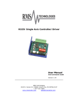
2.7 Connections and I/O
Mains Power 3-pin or 4-pin removable terminal block (P1)
Ethernet Port Standard RJ45 Connector (P2)
I/O Connector Standard 50-pin SCSI (P3)
- Buffered Encoder Output A, B, & Z channels with compliments (5V @ 20mA) (P3)
- Digital Inputs 11 programmable plus 1 dedicated (5-24V) (P3)
- Digital Outputs 4 programmable plus 1 dedicated (5-24V @ 100mA) (P3)
- Analog Input 2 differential; ±10 VDC (12-bits each) (P3)
- Analog Output 1 single ended; ±10 VDC (10-bit) (P3)
- Position Reference Input Step & Direction or Master Encoder (TTL) (P3)
Encoder Feedback (E94P drive) Feedback connector, 15-pin D-shell (P4)
Resolver Feedback (E94R drive) Feedback connector, 9-pin D-shell (P4)
24VDC Power “Keep Alive” 2-pin removable terminal block (P5)
Regen and Bus Power 5-pin removable terminal block (P6)
Motor Power 6-pin pin removable terminal block (P7)
ISO 13849-1 Safety Circuit (option) 6-pin quick connect terminal block (P8)
RS485 Option Module 3-pin terminal block (installed in Option Bay 1) (P21)
CAN Option Module 3-pin terminal block (installed in Option Bay 1) (P21)
DeviceNet Option Module 5-pin terminal block (installed in Option Bay 1) (P23)
PROFIBUS Option Module 9-pin D-shell connector (installed in Option Bay 1) (P24)
MotionView OnBoard Embedded Software (Java-based)
Maximum Servo Cable Length 20 meters (10m if EN55011 compliance required, see 3.2.1)
P2
P3
P1
P4
P5
P6
P7
EPM
W
V
U
2
T1
9402
8diS
P8
Ground Lug
Ground Lug
3
L2
L
123456

14 S94H201D
Technical Data
2.8 PositionServo Dimensions
C
15
12
12
A
38
D B
34 dia = 4.57
4.57
Dimensions in mm S923
Type (1) A (mm) B (mm) C (mm) D (mm) Weight (kg)
E94_020S1N_~ 68 190 190 182 1.1
E94_040S1N_~ 69 190 190 182 1.2
E94_020S2F_~ 68 190 235 182 1.3
E94_040S2F_~ 69 190 235 182 1.5
E94_080S2F_~ 87 190 235 182 1.9
E94_100S2F_~ 102 190 235 182 2.2
E94_020Y2N_~ 68 190 190 182 1.3
E94_040Y2N_~ 69 190 190 182 1.5
E94_080Y2N_~ 95 190 190 182 1.9
E94_100Y2N_~ 114 190 190 182 2.2
E94_120Y2N_~ 68 190 235 182 1.5
E94_180T2N_~ 68 242 235 233 2.0
E94_020T4N_~ 68 190 190 182 1.5
E94_040T4N_~ 95 190 190 182 1.9
E94_060T4N_~ 68 190 235 182 1.4
E94_090T4N_~ 68 242 235 233 2.0
(1) The first “_” equals “P” for the Model 940 encoder based drive or “R” for the Model 941 resolver based drive.
The second “_” equals “E” for incremental encoder (must have E94P drive) or “R” for the standard resolver (must have E94R drive).
The last digit “~” equals M” for MV OnBoard and no ISO 13849-1 circuit or “S” for MV OnBoard plus the ISO 13849-1 circuit.

S94H201D 15
Technical Data
2.9 Clearance for Cooling Air Circulation
>25mm >3mm
>25mm
S924

16 S94H201D
Installation
3 Installation
Perform the minimum system connection. Refer to section 6.1 for minimum connection requirements.
Observe the rules and warnings below carefully:
DANGER!
Hazard of electrical shock! Circuit potentials are up to 480 VAC above earth ground. Avoid
direct contact with the printed circuit board or with circuit elements to prevent the risk of
serious injury or fatality. Disconnect incoming power and wait 60 seconds before servicing
drive. Capacitors retain charge after power is removed.
STOP!
• The PositionServo must be mounted vertically for safe operation and to ensure
enough cooling air circulation.
• Printed circuit board components are sensitive to electrostatic fields. Avoid contact
with the printed circuit board directly. Hold the PositionServo by its case only.
• Protect the drive from dirt, filings, airborne particles, moisture, and accidental
contact. Provide sufficient room for access to the terminal block.
• Mount the drive away from any and all heat sources. Operate within the specified
ambient operating temperature range. Additional cooling with an external fan may
be required in certain applications.
• Avoid excessive vibration to prevent intermittent connections
• DO NOT connect incoming (mains) power to the output motor terminals (U, V, W)!
Severe damage to the drive will result.
• Do not disconnect any of the motor leads from the PositionServo drive unless
(mains) power is removed. Opening any one motor lead may cause failure.
• Control Terminals provide basic isolation (insulation per EN 61800-5-1). Protection
against contact can only be ensured by additional measures, e.g., supplemental
insulation.
• Do not cycle mains power more than once every 2 minutes. Otherwise damage to
the drive may result.
WARNING!
For compliance with EN 61800-5-1, the following warning applies.
This product can cause a d.c. current in the protective earthing conductor. Where
a residual current-operated protective (RCD) or monitoring (RCM) device is used for
protection in case of direct or indirect contact, only an RCD or RCM of Type B is
allowed on the supply side of this product.
UL INSTALLATION INFORMATION
• Suitable for use on a circuit capable of delivering not more than 200,000
rms symmetrical amperes, at the maximum voltage rating marked on the
drive.
• Use Class 1 wiring with minimum of 75ºC copper wire only.
• Shall be installed in a pollution degree 2 macro-environment.

S94H201D 17
Installation
3.1 Wiring
DANGER!
Hazard of electrical shock! Circuit potentials are up to 480 VAC above earth ground. Avoid
direct contact with the printed circuit board or with circuit elements to prevent the risk of
serious injury or fatality. Disconnect incoming power and wait 60 seconds before servicing
the drive. Capacitors retain charge after power is removed.
WARNING!
Leakage current may exceed 3.5mA AC. Minimum size of the protective earth conductor
shall comply with local safety regulations for high leakage current equipment.
STOP!
Under no circumstances should power and control wiring be bundled together. Induced
voltage can cause unpredictable behavior in any electronic device, including motor controls.
WARNING!
The PositionServo drive runs on phase-to-phase voltage. For the standard drive, either a
delta or wye transformer may be used for 3-phase input. However, for reinforced insulation
of user accessible I/O circuits, each phase voltage to ground must be less than or equal to
300VAC rms. This means that the power system must use center grounded wye secondary
configuration for 400/480VAC mains.
Refer to section 4.1.1 for Power wiring specifications.
3.2 Shielding and Grounding
3.2.1 General Guidelines
Lenze recommends the use of single-point grounding (SPG) for panel-mounted controls. Serial grounding
(a “daisy chain”) is not recommended. The SPG for all enclosures must be tied to earth ground at the same
point. The system ground and equipment grounds for all panel-mounted enclosures must be individually
connected to the SPG for that panel using 14 AWG (2.5 mm2) or larger wire.
In order to minimize EMI, the chassis must be grounded to the mounting. Use 14 AWG (2.5 mm2) or larger
wire to join the enclosure to earth ground. A lock washer must be installed between the enclosure and
ground terminal. To ensure maximum contact between the terminal and enclosure, remove paint in a
minimum radius of 0.25 in (6 mm) around the screw hole of the enclosure.
Lenze recommends the use of the special PositionServo drive cables provided by Lenze. If you specify cables
other than those provided by Lenze, please make certain all cables are shielded and properly grounded.
It may be necessary to earth ground the shielded cable. Ground the shield at both the drive end and at the
motor end.
If the PositionServo drive continues to pick up noise after grounding the shield, it may be necessary to add
an AC line filtering device and/or an output filter (between the drive and servo motor).

18 S94H201D
Installation
EMC
Compliance with EN 61800-3:2004
In a domestic environment this product may cause radio interference. The user may be required to
take adequate measures
Noise emission
Drive Models ending in the suffix “2F” are in compliance
with class A limits according to EN 55011 if installed
in a control cabinet and the motor cable length does
not exceed 10m. Models ending in “N” will require an
appropriate line filter.
Installation according to EMC
Requirements
E
D
B C
A
F
S930
A Screen clamps
B Control cable
C Low-capacitance motor cable
(core/core < 75 pF/m, core/screen < 150 pF/m)
D Earth grounded conductive mounting plate
E Encoder/Resolver Feedback Cable
F Footprint or Sidemount Filter (optional)
3.2.2 EMI Protection
Electromagnetic interference (EMI) is an important concern for users of digital servo control systems. EMI
will cause control systems to behave in unexpected and sometimes dangerous ways. Therefore, reducing
EMI is of primary concern not only for servo control manufacturers such as Lenze, but the user as well.
Proper shielding, grounding and installation practices are critical to EMI reduction.
3.2.3 Enclosure
The panel in which the PositionServo is mounted must be made of metal, and must be grounded using the
SPG method outlined in section 3.2.1.
Proper wire routing inside the panel is critical; power and logic leads must be routed in different avenues
inside the panel.
You must ensure that the panel contains sufficient clearance around the drive. Refer to section 2.9
suggested cooling air clearance.
3.3 Line Filtering
In addition to EMI/RFI safeguards inherent in the PositionServo design, external filtering may be required. High
frequency energy can be coupled between the circuits via radiation or conduction. The AC power wiring is
one of the most important paths for both types of coupling mechanisms. In order to comply with IEC 61800-
3:2004, an appropriate filter must be installed within 20cm of the drive power inputs.
Line filters should be placed inside the shielded panel. Connect the filter to the incoming power lines
immediately after the safety mains and before any critical control components. Wire the AC line filter as
close as possible to the PositionServo drive.
/