Somfy Dexxo Pro 1000 io User manual

Category
Garage Door Opener
Type
User manual

This manual is also suitable for

1
EN
CONTENTS
GENERAL PRESENTATION ����������������������������������������������� 2
SAFETY INSTRUCTIONS ������������������������������������������������� 2
Caution 2
Safety instructions 2
PRODUCT DESCRIPTION ������������������������������������������������� 2
Product components 2
Area of application 2
POINTS TO CHECK PRIOR TO INSTALLATION ������������������������������� 3
Preliminary checks 3
Safety instructions 3
INSTALLATION ���������������������������������������������������������� 3
Installation height 3
Detailed description of installation steps 3
PROGRAMMING �������������������������������������������������������� 5
Programming button description 5
End limit setting and self-learning 5
Keytis remote control description 5
Keygo remote control description 5
Fitting the battery for Keytis remote controls 6
Programming Keytis remote controls 6
Programming Keygo remote controls 7
OPERATING TEST ������������������������������������������������������� 7
Using Keytis remote controls 7
Using Keygo remote controls 7
Obstacle detection function 7
Built in lighting operation 7
CONNECTING PERIPHERALS ��������������������������������������������� 8
Description of the various peripherals 8
Electrical connections for the various peripherals 8
SETUP ����������������������������������������������������������������� 9
General setup diagram 9
Meanings of the various parameters 9
PROGRAMMING KEYGO IO REMOTE CONTROLS FOR FULL AND
PARTIAL OPENING OPERATION ������������������������������������������ 10
CLEARING REMOTE CONTROLS AND ALL SETTINGS ������������������������ 11
Clearing remote controls 11
Resetting all settings 11
LOCKING PROGRAMMING ����������������������������������������������� 11
REFITTING COVERS ���������������������������������������������������� 11
TROUBLESHOOTING ��������������������������������������������������� 12
Operating codes displayed 12
Programming codes displayed 12
Error and failure codes displayed 12
Accessing stored data 12
TECHNICAL SPECIFICATIONS �������������������������������������������� 13
Dimensions 13
io-homecontrol® provides advanced and secure radio technology that is easy to install.
io-homecontrol® labelled products communicate with each other, improving comfort,
security and energy savings.
www.io-homecontrol.com
2
EN
PRODUCT DESCRIPTION
Product components Fig. 1
Key Number Description Key Number Description
1 1 Motor head 16 2 Shaft
2 1 Motor cover 17 2 Circlips
3 1 Built-in light cover 19 4 Self-shaping Ø 4x8 screw
4 1 Lintel bracket 20 2 Special screw for plastic Ø 3.5x12
5 1 Door bracket 21a 1 Single part rail
6 2 Ceiling bracket 21b 1 Two part rail
7 2 Motor head bracket 21b1 1 Sleeve
8 1 Manual release cord 21b2 8 Self-shaping Ø 4x8 screw
9 1 Link arm 22 2 HM8 self-locking nut
10 1 Travel stop 23 2 Bracket
11 4 Chain retainer pad 24 1 Spacer
12 1 Power cable 25a 1 Keytis 4 io remote control
13 4 Hex. head M8x16 bolt 25b 2 Keygo io remote control
14 4 Hex. head M8x12 bolt & washer 26 1 230 V 40 W E14 socket light bulb
15 6 HU8 nut 27 1 Antenna
Area of application Fig. 2
Types of doors (Fig.2)
A: Projecting up and over door.
B: Sectional door:
- if the door’s upper prole is a specic one, use the “sectional door mounting bracket” ref.: 9009390.
- if the door surface exceeds 10 sq. metres, use the “sectional door adapter” ref.: 2400873.
GENERAL PRESENTATION
This product complies with the “safety, specic rules for powering vertically opening garage doors in residential use” requirements (standard EN
60335-2.95). When installed in line with these instructions and in compliance with the “Installation Checklist”, the product will be compliant with
standards EN 13241-1 and EN 12453.
The instructions referred to in the installation manual and instructions for use of this product are designed to prevent damage to property and
personal injury along with compliance with the above standards. Failure to comply with these instructions absolves Somfy from any liability resulting
from damage that may be caused. Dexxo Pro is a product that must be installed inside the garage with an integrated back-up control system.
Somfy hereby declares that the device is compliant with the essential demands and other relevant requirements of directive 1999/5/CE. A
declaration of compliance is available from the web site at www.somfy.com/ce (Dexxo Pro io). This product is suitable for use in the European
Union and in Switzerland.
SAFETY INSTRUCTIONS
Caution
These are important safety instructions. Always follow the instructions, incorrect installation may lead to serious injury.
Safety instructions
Before installing the motor drive unit, remove all unessential lines or chains and switch off all equipment that is not essential for motorised door
operation.
Before installing the motor drive unit, make sure that the door is in good mechanical condition, that it is properly balanced and that it opens and
closes correctly.
Locate all control systems at least 1.5 metres above oor level, making sure that they are visible from the entrance to the garage but safe from
moving parts.
Position the manual release cord no more than 1.8 metres above oor level.
Where a removable release mechanism is used, we recommend storing it close to the door.
Fix the label describing the manual release procedure close to the release mechanism.
Fix the warning labels describing the hazards of door motion close to any xed control mechanisms installed and make sure that the labels are
clearly visible to the user.
After installation, make sure that the mechanism is correctly adjusted and that the motor drive unit reverses its motion when the door encounters
an obstacle that is at least 50 mm from oor level.
After installation, make sure that no part of the door overhangs an area accessible to the public.
After installation, make sure that the motor drive unit inhibits or stops the door opening motion when the door is loaded down with a 20 kg weight
attached to a central position of the door’s bottom edge.
In accordance with standard EN12453 concerning the safe use of motorised doors and gates, the remote control of an automatic garage door
which is not visible to the user, particularly using the TAHOMA unit, always requires a photoelectric cell type safety device to be installed on this
automatic function.Failure to comply with these instructions absolves SOMFY of any liability resulting from damage that may be caused.
3
EN
Installation height Fig. 4
Measure the distance “D” between the door’s highest point and the ceiling.
If “D” is between 35 and 200 mm, mount the complete system straight onto the ceiling.
If “D” exceeds 200 mm, mount the complete assembly so that the height “H” falls between 10 and 200 mm.
Detailed description of installation steps Fig. 5 to 15
Mounting the lintel bracket and the door bracket (Fig. 5)
When installing the system directly onto the ceiling (ush with the ceiling), the lintel bracket can be mounted on the ceiling, if necessary recessed
from the lintel by up to 200 mm max. (Fig. 5- ).
INSTALLATION
C: Sideways opening sliding door:
- for side wall mounting, use:
- a belt transmission rail
- an “adjustable cranked arm” ref.: 9014481.
- for ceiling mounting, use:
- an “articulated arm” ref.: 9014482.
D: Swinging door. Use the swinging door kit, ref.: 2400459.
E: Semi and non projecting door. Use:
- a high performance transmission rail
- “the semi and non projecting door kit” ref.: 2400458.
Some doors of this type may prove impossible to automate. Contact SOMFY’s technical department.
Door dimensions (Fig. 3)
For maximum door heights, the motor travel can be optimised:
By installing the motor head at a 90° angle (Fig. 7- ).
By xing the lintel bracket to the ceiling, behind the lintel itself by up to 200 mm (Fig. 5- )
By cutting the link arm to size.
Preliminary checks
Check the garage door can be operated manually and runs smoothly. Ensure the door is in good mechanical condition (pulleys, mounts…) and
is correctly balanced (spring tension).
Remember that any work performed on door springs may be dangerous.
The structure of your garage (walls, lintel, inside surfaces, cross members, door rails…) are used to mount the Dexxo Pro system. Reinforce
them where necessary.
Never splash water onto the system. Never install Dexxo Pro in a location where water may cause damage.
The bottom edge of the door should be tted with a rubber strip to avoid hard contact and enhance the contact surface.
If the garage door is the only entry point into the garage, t an external release (external release keylock (ref. 9012961) or an external release
(ref. 9012962) and include a back-up battery (ref. 9001001).
If the garage door includes a separate pedestrian door, the door must be tted with an interlock to prevent garage door movement when the
pedestrian door is open (pedestrian door safety kit ref. 2400657).
If the garage door opens on to a public road, install an indicator light, such as a ashing orange light (ref. 9015171).
If the garage door operates in automatic mode, install a photoelectric cell type safety system (ref. 9014994 or ref. 9013647) and a ashing orange
light type indicator.
Make sure that the door does not comprise any accessible parts.
Unlocking the door may trigger uncontrolled door movement if the door is not balanced correctly.
Safety instructions
Safety instructions must be complied with throughout the installation process:
Take off any personal jewellery (bracelet, chain or others) during installation work.
During drilling and welding work, always wear safety glasses and suitable protection.
Always use suitable tools.
Take care when handling the motor drive system.
Never connect the mains power supply or the battery back-up system before completing the installation process.
Never use high pressure water systems for cleaning purposes.
POINTS TO CHECK PRIOR TO INSTALLATION
4
EN
Assembling the two part rail (Fig. 6)
[1] [2] [3]. Unfold the two parts of the rail.
Ensure that the chain or belt is not twisted.
[4]. Assemble the two parts of the rail using the sleeve.
[5]. Mount the complete assembly using the eight mounting screws.
[6]. Tighten the nut to tension the chain or belt. The compressed rubber must measure 18 and 20 mm.
The mounting screws must not penetrate the rail (do not drill).
When installing the system directly onto the ceiling, do not use the sleeve mounting screws.
Fitting the rail onto the motor head (Fig. 7)
Fitting the complete assembly onto the garage ceiling (Fig. 8 to 10)
Fitting to the lintel bracket (Fig. 8)
Ceiling mounting
Flush with the ceiling: mount the system directly onto the ceiling using the rail (Fig. 9).
It is possible to add mounting points at the motor head level (Fig. 9- ).
Hung from the ceiling: two options:
- mount the system at the motor head (Fig. 10-
a
).
- mount the system at the rail (Fig. 10-
b
).
To add an adjustable intermediate mounting along the rail, or a mounting at a dimension h between 250 mm and 550 mm, use the ceiling
mounting kit ref.: 9014462 (Fig. 10- ).
Fitting the arm onto the door and the trolley (Fig. 11)
[1]. Release the trolley using the manual release cord.
[2]. Bring the trolley up to the door.
[3]. Attach the arm to the door bracket and the trolley.
Adjusting and fastening the opening travel stop (Fig. 12)
[1]. Release the trolley from the runner using the manual release mechanism and bring the door to the open position.
Do not open the door fully, but position it so that it does not reach its own travel stop.
[2]. Slot the travel stop (10) into the rail then turn it by 90°.
[3]. Position the travel stop against the trolley.
[4]. Moderately tighten down the mounting screw.
Do not tighten the mounting screw all the way down. Excessive tightening can damage the screw and cause the travel stop
not to remain in place.
Fitting the chain retainer pads (Fig. 13)
For chain rails only.
These pads are used to limit spurious noise linked to chain friction within the rail. Position each of the pads in the rst hole in the rail after the travel stop.
Make sure that the pad is pressed in all the way so that its positioning pin is accessible outside of the rail.
Checking the chain or belt tension (Fig. 14)
The rails are supplied ready tensioned and inspected. If necessary, adjust the tensioning.
The rubber or tension spring must never be fully compressed during operation.
Connecting the mains power supply (Fig. 15)
[1]. Remove the motor cover and the protective sheet.
[2]. Fit the light bulb.
[3]. Connect to the antenna.
[4]. Connect to the mains supply.
Plug the power cable into a suitable power outlet that complies with electric power requirements. The electric
supply must be suitably protected (a fuse or circuit breaker with a 5 A rating) and a residual current device (30 mA).
An omnipolar disconnection mechanism must be provided for the power supply:
. by using a power cord with a mains splug that can be disconnected, or
. by tting a switch that ensures a contact separation distance of at least 3 mm for each pole (refer to standard EN60335-1).
Make sure that the manual release cord is located at a maximum height of 1.80 metres off the ground.
If necessary, extend the cord.
5
EN
End limit setting and self-learning Fig. 16
PROGRAMMING
Programming button description
For swinging doors, change the P9 setting before starting self-learning.
[1]. Press the “SET” button until the light comes on (2 s).
The display shows “S2
[2]. Control the motor using the “+” or “-” buttons so that the transmission system runner moves to link up with the trolley and closes the door.
Pressing and holding the “-” button closes the door.
Release the “-” button before the motor has time to force against the door.
Pressing and holding the “+” button opens the door.
[3]. Adjust the closed position using the “+” or “-” buttons.
Release the “-” button before the motor has time to force against the door.
[4]. Press “OK” to validate the closed end limit position and start the self-learning cycle.
The door runs through a complete Open Close cycle.
If learning was correct, the display will show “C1”.
If the learning cycle was not completed correctly, the display will show “S1”.
During the learning cycle:
If the door is moving, pressing any button will stop the movement and interrupt the learning mode.
If the door is stopped, pressing “SET” once will exit the learning mode.
You can call up the learning mode at any time, even when the learning cycle has already been executed and the display shows “C1”.
Keytis remote control description Fig. 17a
1 Individual control buttons
2 General STOP button
3 General CLOSE button (Keytis 4 home io only)
4 Operation indicator light On Intermittent Blinking
5 Low battery indicator light
6 Closing clip
7 PROG button: programming the transmitter
8 KEY button: memorising the system key
Keygo remote control description Fig. 17b
1 Individual control buttons
2 Operation indicator light On Intermittent Blinking
. Press for 2 s: memorise remote controls
. Press for 7 s: delete remote controls
. Modifying a setting value
. Using the forced mode
. Selecting a setting
. Start the learning cycle
. Conrm setting selection
. Conrm setting value
. Press for 0.5 s: call up and exit the setup menu
. Press for 2 s: start learning
. Press for 7 s: clear learning and settings
. Stop learning
6
EN
Fitting the battery for Keytis remote controls Fig. 18
Programming Keytis remote controls Fig. 19 to 23
. If the installation already comprises other io-homecontrol® products with at least one programmed remote control
then you must perform the Memorising the system key step before programming the remote controls (Fig. 20).
. If the Keytis io remote control to be programmed is the system’s rst remote control, then go straight to Programming the
Keytis remote control step (Fig. 21 to 23).
The operations for memorising the system key and to program a remote control by copying another Keytis remote control are
only possible at the installation location. To gain authorisation to transfer its system key or its programming, the previously
programmed remote control must be able to establish radio communication with an installation receiver.
Memorising the system key (Fig. 20).
[1]. Set existing remote control no. 1 to the key transfer mode:
With a Keytis, Telis, Impresario, Composio remote control: press the “KEY” button until the green indicator comes on (two seconds).
With another remote control: refer to its documentation.
[2]. Briey press the “KEY” button on the new remote control. Wait for the conrmation beep (a few seconds).
Programming the Keytis remote control (Fig. 21 to 23)
Before programming the remote control, make sure that it has already memorised the system key.
Each control button is programmed individually.
A button that is already programmed cannot be programmed on a second receiver. To see if a button is already programmed, press it:
button programmed → green indicator comes on.
button not programmed → orange indicator comes on.
To clear a previously programmed button, refer to the section on Clearing Keytis remote controls.
There are two ways to program the remote control:
Programming from a Dexxo Pro motor.
Programming by copying a previously programmed Keytis remote control.
Programming from a Dexxo Pro motor (Fig. 21)
[1]. Press the “PROG” button on the Dexxo Pro until the light comes on (two seconds).
[2]. Briey press the “PROG” button on the remote control.
Wait for the second beep and for the green indicator to start blinking quickly.
This may take from a few seconds to around a minute depending on the number of products connected to the system.
[3]. Briey press the button chosen to control the Dexxo Pro motor.
The remote control sounds a conrmation beep and the Dexxo Pro motor’s light blinks for ve seconds.
Programming by copying a previously programmed Keytis remote control
Completely copy the programming of a Keytis remote control (Fig. 22)
This operation is used to copy all of the buttons programmed from an already programmed remote control.
[1]. Press the “PROG” button on the previously programmed remote control until the green indicator comes on (two seconds).
[2]. Briey press the “PROG” button on the new remote control.
Wait for the second beep and for the green indicator to start blinking rapidly (a few seconds).
Individually copy the programming of a Keytis remote control button (Fig. 23)
This operation is used to copy the programming of a single button from an already programmed remote control.
[1]. Press the “PROG” button on the previously programmed remote control until the green indicator comes on (two seconds).
[2]. Briey press the button to copy on the previously programmed remote control.
[3]. Briey press the “PROG” button on the new remote control.
Wait for the conrmation beep (after a few seconds).
[4]. Briey press the button chosen to control Dexxo Pro on the new remote control.
It is impossible to program Keytis remote controls in the following cases:
. The remote control has not memorised the system key.
. A number of installation receivers are in programming mode.
. A number of remote controls are in key transfer or programming modes.
Any incorrect programming is indicated by a series of fast beeps together with the orange indicator blinking on the Keytis
remote control.
At this stage in the installation process, the Dexxo Pro motor drive unit is ready to run.
7
EN
Programming Keygo remote controls Fig. 24 and 25
Each control button is programmed individually.
To clear a previously programmed button, refer to the section entitled "Clearing Keygo remote controls".
There are two ways to program the remote control:
Programming from a Dexxo Pro motor.
Programming by copying a previously programmed Keygo io remote control.
Programming from a Dexxo Pro motor (Fig. 24)
[1]. Press the “PROG” button on the Dexxo Pro until the light comes on (2 seconds).
[2]. Simultaneously press the outer right and outer left buttons on the remote control.
The remote control indicator light ashes.
[3]. Briey press the selected button to actuate the Dexxo Pro motor.
The light of the Dexxo Pro motor ashes for 5 seconds.
Programming by copying a previously programmed Keygo io remote control (Fig. 25)
This operation is used to copy the programming of a previously programmed remote control button.
[1]. Simultaneously press the outer right and outer left buttons on the previously programmed remote control (A) until the green indicator light
comes on (2 seconds).
[2]. Press the button for 2 seconds to copy the previously programmed remote control (A).
[3]. Simultaneously briey press the outer right and outer left buttons on the new remote control (B).
[4]. Briey press the selected button to actuate the Dexxo Pro on the new remote control (B).
At this stage in the installation process, the Dexxo Pro motor drive unit is ready to run.
OPERATING TEST
Using Keytis remote controls Fig. 26
Using Keygo remote controls Fig. 27
Obstacle detection function Fig. 28 and 29
The detection of an obstacle during door opening will stop the door (Fig. 28).
The detection of an obstacle during door closure will reopen the door (Fig. 29).
Make sure that obstacle detection works when the door encounters an obstacle 50 mm from the ground.
Built in lighting operation
The light will come on every time the motor drive unit is operated. It will go out automatically after one minute once the door stops. This time delay
is adjustable (refer to the Setup chapter). Repetitive use which causes the light to stay on continually may result in an automatic cut-off condition
triggered by the thermal cut out protection mechanism.
8
EN
CONNECTING PERIPHERALS
Description of the various peripherals Fig. 30
Key Description Key Description
1Orange light 6Battery
2Remote lighting 7Pedestrian door safety kit
3Code keypad 8Photoelectric cells
4Keyswitch 9Reex type cells
5Aerial 10 Sensor bar
Electrical connections for the various peripherals Fig. 30 to 39
Cut the electric power supply to the motor before performing any work on peripherals. If the display remains off after working on the system,
check the wiring (for possible short circuits or polarity reversals).
General electrical diagram (Fig. 30)
Photoelectric cells (Fig. 31)
It is compulsory to install photoelectric cells:
- If automatic closing is activated (P0=1)
- If the automatic function is controlled remotely (not visible to the user)
Two types of connections can be made:
A: Standard (without self test): program the setting “P2” = 2.
B: With self test: program the setting “P2” = 1.
This means that an automatic test is conducted to check photoelectric cell operation every time the door operates.
If the test fails, no door movement is possible.
Reex photoelectric cell (Fig. 32)
With self test: program the setting “P2” = 1.
This means that an automatic test is conducted to check photoelectric cell operation every time the door moves.
If the test fails, no door movement is possible.
Sensor bar (Fig. 33)
With self test: program the setting “P2” = 1.
This is used to perform an automatic test of sensor bar operation every time the door moves.
If the test result is negative, no door movement is possible.
Make sure you have correctly congured parameter “P2” taking into account the photoelectric cells or the sensor bar.
Orange light (Fig. 34)
Program the setting “P1” depending on the required operating mode:
Without warning before door movement: “P1” = 0.
With a 2 s warning before door movement: “P1” = 1.
Code keypad (Fig. 35)
Pedestrian door safety kit (Fig. 36)
When the pedestrian door contact is tted, it must be connected in place of the jumper normally tted between terminals 5 and 6.
If the pedestrian door contact is removed, the jumper between terminals 5 and 6.
Battery (Fig. 37)
Aerial (Fig. 38)
Remote lighting (Fig. 39)
Class 2 (double insulation) light units that are connected do not require an earth connection.
Various types of lighting can be connected without exceeding a total power consumption of 500 W.
9
EN
SETUP
General setup diagram Fig. 40
Meanings of the various parameters
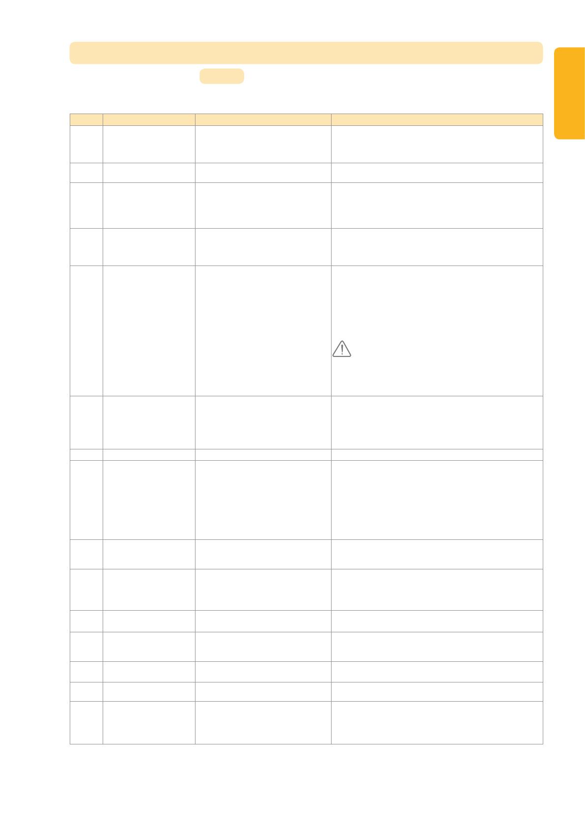
Code Description Values Comments
P0 Operating mode 0: sequential
1: automatic closure
Automatic closure mode operation is only possible if photoelectric
cells are tted, i.e. P2=1 or P2=2.
In automatic closure mode, the door is automatically closed after the
end of the time delay set with setting “t0”.
P1 Orange warning light 0: without advance warning
1: with 2 s advance warning
If the garage opens onto a public road, always select with advance
warning: P1=1.
P2 Safety input 0: no safety mechanism
1: safety mechanism with self test
2: safety mechanism without self test
If value 0 is selected, the safety input is not taken into account.
If value 1 is selected, the system’s self test is run at the start of every
operating cycle.
If value 2 is selected, the safety system runs without a self test: it is
essential to test its proper operation every six months.
P3 Obstacle detection
sensitivity
0: low sensitivity
1: low sensitivity
2: standard
3: high sensitivity
If this setting is changed, it is essential to run the force measurement
sequence at the end of the installation procedure or install a sensor
bar.
P4 Partial opening cycle 0: not valid
1: valid
If the partial opening cycle is validated:
For Keytis remote controls
. a short press on the remote control button causes partial opening.
. a long press on the remote control button causes full opening.
For Keygo remote controls
Pressing the button programmed for partial opening causes partial
opening; pressing the button programmed for full opening causes full
opening.
When this parameter is activated, pressing a previously
programmed remote control button will partially open the
gate; an additional command must then be performed
so that the button fully opens the gate again (refer to
"Programming Keygo io remote controls for full and partial
opening operation").
P5 Closing speed 0: slowest speed: approx. 3.5 cm/s
to
9: fastest speed: approx. 18 cm/s
By default, 6: approx. 12 cm/s
If this setting is changed, it is essential to run the force measurement
sequence at the end of the installation procedure or install a sensor
bar.
If spurious detection of obstacles occurs when this parameter is
modied, end limit setting and auto-programming will have to be
carried out again.
P6 Partially open position Storing the position as illustrated in Fig. 42.
P7 Closure approach speed 0: no slowdown
1: short soft stop
2: long soft stop
P7=0: the door does not slow before closure.
P7=1: the door speed slows 20 centimetres before closure.
P7=2: the door speed slows 50 centimetres before closure.
If this setting is changed, it is essential to run the force measurement
sequence at the end of the installation procedure or install a sensor
bar.
If spurious detection of obstacles occurs when this parameter is
modied, end limit setting and auto-programming will have to be
carried out again.
P8 Opening speed 0: slowest speed: approx. 3.5 cm/s
to
9: fastest speed: approx. 18 cm/s
If spurious detection of obstacles occurs when this parameter is
modied, end limit setting and auto-programming will have to be
carried out again.
P9 Choice of operating direction
(type of door)
0: direction 1: all types of doors except
swinging doors
1: direction 2: swinging doors
If this setting requires modication the end limit setting must be
repeated along with self-learning.
A0 Safety action prior to
opening (safety ADMAP)
0: no effect
1: movement rejected
If value 1 is selected, triggering the safety input will inhibit door
opening.
A1 Safety action during closure 1: stop
2: stop + partial re-opening
3: fully reopen
Value 1 is not allowed when using a sensor bar on the safety input.
A2 Obstacle detection action
during closure
2: stop + partial re-opening
3: fully reopen
t0 Automatic closure time delay 0 to 12 (time delay value = value x 10 s)
2: 20 s
t1 Lighting time delay 0 to 60 (time delay value = value x 10 s)
6: 60 s
Remark: Due to the thermal cut out protection system, the integrated
light may cut out automatically if it is used for an extended length of
time. We therefore recommend selecting a light time delay in excess
of 2 mn (t1=12 or 120s) only when remote lighting is used.
(Boldface text = default values)
10
EN
Programming example: setting the ”P7” closure approach speed (Fig. 41)
Setting up a long soft stop function zone “P7” = 2.
Special case: adjusting the position of the door for partial opening (Fig. 42)
Select setting “P6” and validate by pressing “OK”.
Move the door to the desired partially open position:
. Pressing and holding the “-” button will close the door.
. Pressing and holding the “+” button will open the door.
. Validate by pressing “OK”.
. Exit the menu with “SET”.
Forced mode (Fig. 43)
This function is used to move the door to a specic position:
. Pressing and holding the “-” button will close the door.
. Pressing and holding the “+” button will open the door.
Programming a Situo Telis Composio Impresario type remote control (Fig. 44)
Before programming the remote control, make sure that it has already memorised the system key. (Refer to the corresponding remote control
documentation).
[1]. Press the “PROG” button on Dexxo Pro until the light comes on.
[2]. Briey press the “PROG” button on the remote control.
Wait for the Dexxo Pro light to blink.
This may take from a few seconds to around a minute depending on the number of products connected to the system.
Remark: Dexxo Pro can memorise up to six Situo remote controls. For other types of remote controls, no limit applies.
PROGRAMMING KEYGO IO REMOTE CONTROLS FOR FULL AND
PARTIAL OPENING OPERATION
In order for the garage door to open fully and partially, parameter P4 must be activated (refer to the section entitled "Parameter setting").
When parameter P4 is activated, all the remote control buttons previously programmed during commissioning become
programmed buttons to partially open the garage door.
An additional memorising command must be performed on buttons which are used to fully open the garage door.
The operations to be performed differ according to the desired function for the button being programmed (full or partial opening), and depending
on the memorisation which has already been performed on the button prior to activation of parameter P4.
Switch to full opening for a button previously memorised during commissioning (Fig.45)
[1]. Simultaneously press the large button and the small button in the centre of the remote control.
The remote control indicator light ashes.
[2]. Press the remote control button previously memorised during commissioning within 10 seconds.
The button for full opening has been memorised.
Memorise a button that has not yet been programmed to trigger partial opening (Fig.24)
[1]. Press the “PROG” button on the Dexxo Pro until the light comes on (2 seconds).
[2]. Simultaneously press the outer right and outer left buttons on the remote control.
The remote control indicator light ashes.
[3]. Briey press the selected button to partially open the Dexxo Pro motor.
The light of the Dexxo Pro motor ashes for 5 seconds.The button for full opening has been memorised.
Memorise a button that has not yet been programmed to trigger full opening (Fig.46)
[1]. Press the “PROG” button on the Dexxo Pro until the light comes on (2 seconds).
[2]. Simultaneously press the outer right and outer left buttons on the remote control.
The remote control indicator light ashes.
[3]. Briey press the selected button to operate the Dexxo Pro motor for full opening.
The light of the Dexxo Pro motor ashes for 5 seconds.
[4]. Simultaneously press the large button and the small button in the centre of the remote control.
The remote control indicator light ashes.
[5]. Press the remote control button that you wish to use for full opening within 10 seconds.
The button for full opening has been memorised.
11
EN
SPECIAL OPERATION
After a power outage, the next time the door is moved, it must be opened completely; the motor must be stopped at the upper stop before it can
start operating normally again.
For other specic operations, see page 5 of the user manual.
CLEARING REMOTE CONTROLS AND ALL SETTINGS
Clearing remote controls Fig. 47 to 49
Clearing Keytis or Keygo remote controls
Individually clearing a remote control button
This can be done:
by programming from the Dexxo Pro motor (Fig. 21).
Programming a previously programmed button automatically clears any previously stored programming settings.
by directly clearing the remote control (only for Keytis remote controls) (Fig. 47).
Simultaneously press the “PROG” button and the BUTTON to be cleared on the remote control.
Clearing all remote controls (Fig. 48)
[1]. Press the “PROG” button on Dexxo Pro until the light blinks (seven seconds). This will:
Clear the system key memorised by Dexxo Pro,
Clear the programming for all memorised remote controls.
[2]. For Keytis remote controls, repeat the direct clearing procedure for all of the Keytis remote control buttons programmed on the Dexxo Pro
system: Fig. 47.
Keytis remote control general reset (Fig. 49)
Simultaneously press the “PROG” and “KEY” buttons. This will:
perform a program general clear action (all buttons),
clear all settings from the remote control (refer to Keytis io remote control documentation),
change the system key memorised by the remote control.
Resetting all settings Fig. 50
Press the “SET” button until the light goes out (7 s).
This clears all previously stored settings and returns them to their default values.
LOCKING PROGRAMMING (Fig. 51)
Used to lock the programming settings (end limit setting, self-learning, setup).
Simultaneously press the “SET”, “+” and “-” buttons:
- start by pressing “SET”.
- pressing “+” and “-” must take place within two seconds.
To access programming mode once again, repeat the same procedure.
REFITTING COVERS
Ret the motor head and built in light covers (Fig. 52).
12
EN
TROUBLESHOOTING
Operating codes displayed
Code Description Comments
C1 Waiting for a command
C2 Door opening
C3 Waiting for the door to close
C4 Door closing
C5 Obstacle detection Displayed during obstacle detection then for 30 s.
C6 Safety input active Displayed after a movement request or during movement, when the safety input is active.
This display is maintained as long as the safety input is active.
C9 Pedestrian door safety contact active Displayed after a movement request or during movement, when the pedestrian door contact is open.
The display is maintained as long as the pedestrian door contact remains open.
Ca Safety mechanism self test Displayed during safety mechanism self tests.
Cd Working from back-up battery
Waiting for a command
Programming codes displayed
Code Description Comments
S1 Awaiting setting Pressing the “SET” button for 2 s starts the learning mode.
S2 Learning mode Pressing the “OK” button starts the learning cycle: the S2 display blinks during the entire cycle.
Pressing the “+” or “-” buttons will control the motor in forced mode.
F0 Awaiting motor control memorisation Pressing a remote control button will assign this button to motor control.
Pressing the “PROG” button will call up the “Awaiting remote lighting control memorisation mode: F1”.
Error and failure codes displayed
Code Description Comments Action required?
E1 Maximum force reached During learning, the door requires too
much force for the motor.
Check door balance and correct operation by manual
operation.
E4 Safety mechanism self test fault The safety device self test failed Check that “P2” is setup correctly depending on the devices
connected to the safety input.
Check safety device wiring.
When photoelectric cells are used, check their proper
alignment.
Eb Other faults and failure conditions These codes correspond to various
electronic circuit board failures.
Cut the power supply (mains & battery back-up), wait for a few
minutes then re-connect the power supply.
Perform a learning cycle.
If the fault persists, contact Somfy Technical Support.
Accessing stored data
To access stored data, select the “Ud” setting then press “OK” as shown in Fig. 40.
Data Description
U0 Total cycle counter: tens and units
U1 Total cycle counter: thousands and hundreds
U2 Total cycle counter: hundreds of thousands
U3 Cycle counter with obstacle detection: tens and units
U4 Cycle counter with obstacle detection: thousands
U5 Number of control channels memorised (single direction remote control only)
d0 to d9 Log of the last ten faults
dd Clears the fault log: press “OK” for 7 s (Fig.40).
13
EN
(1) Maximum load for motor to start and drive door for at least 5 cm (according to RAL-GZ denition)
171 min
63.6
140
125
Available travel: 2,555 / 3,155
Overall length: 3,295 / 3,895
Overall length: 3,153 / 3,753
65.5
224.4
224.4
Fixation: 2,982 / 3,582
Rail: 2,900 / 3,500
Rail : 2,900 / 3,500
33.5
130.9
404.2
404.2 106
313.6
254.1
139.5
164.4
150.1
112.2
TECHNICAL SPECIFICATIONS
Dexxo Pro 800 io Dexxo Pro 1000 io
BASIC TECHNICAL CHARACTERISTICS
Mains supply 230 V - 50 Hz
Max. power consumption Standby-Operation 5 W - 600 W (with 500 W remote lighting)
Traction force Peak force
Starting force (1)
800 N
650 N
1000 N
800 N
Use
Number of Opening/Closing cycles per day
20 cycles max. per day with a standard rail - 50 cycles max. per day with a high performance rail
tested for 36,500 cycles with a standard rail and 90,000 cycles with a high performance rail
Max. speed 18 cm/s
Programming interface 7 buttons - 2 character LCD display
Operating temperature - 20 ° C / + 60 ° C - indoor dry - IP 20
Travel end limits Mechanical stopper at opening
Memorized end limit position at closing
Electrical insulation Class 2: double insulation
Built in lighting 230 V / 40 W ; E14 socket
Somfy radio frequency 868 - 870 MHz
Number of channels that can be memorised Situo io : 6 Others: unlimited
CONNECTIONS
Safety input Type
Compatibility
Dry contact: NC
Photoelectric TX/RX cells - Reex cell - Sensor strip with dry contact output
Pedestrian door safety input Dry contact: NC
Wired control input Dry contact: NO
Remote lighting output 230 V - 500 W - class 2
Orange light output 24 V - 15 W with built in ashing control
24 V controlled power supply output Yes: for possible photoelectric TX/RX cell self-test
Safety input test output Yes: for possible reex cell or sensor strip self-test
Accessory power supply output 24 V - 500 mA max
Remote aerial input Yes: io aerial compatible (Réf. 9013953)
Backup battery input
Autonomy
Yes: battery pack compatible (Réf. 9001001)
12 hours; 1 to 3 cycles depending on door
Charge time: 48 hours
OPERATION
Forced operation mode By pressing and holding the motor control button
Lighting time delay (after movement) Programmable : 60 s to 600 s
Automatic closing mode Yes: programmable closing time delay from 10 to 120 s
Orange light pre-warning Programmable: with or without prior warning (duration set to 2 s)
Safety input operation While closing
Before opening
(Dangerous Movement Area Accessible
to the Public)
Programmable: Stop - Partial re-opening - Full reopening
Programmable: no effect or motion refused
Built-in obstacle detection Adjustable sensitivity: 4 levels
Operation when an obstacle is detected Programmable : partial re-opening or full reopening
Preset partial opening command Yes can be selected: adjustable partial opening position
Progressive start up Yes
Opening speed Programmable from 3.5 cm/s to 18 cm/s: 10 possible values
Closing speed Programmable from 3.5 cm/s to 18 cm/s: 10 possible values
Closure approach speed Programmable: does not slow down, short slowdown zone (30 cm),
long slowdown zone (50 cm)
Troubleshooting Recording and accessing data: Cycle counter, cycle counter with obstacle detection, number of
radio channels stored, history of the last ten defects recorded.
Dimensions
14
EN
1
EN
somfy.com
Dexxo Pro io
User Manual
5048554E
2
EN
GENERAL PRESENTATION ����������������������������������������������� 2
The world of Somfy 2
Support 2
SAFETY INSTRUCTIONS ������������������������������������������������� 3
Standards 3
Safety instructions 3
PRODUCT PRESENTATION ����������������������������������������������� 3
Description 3
OPERATION AND USE ��������������������������������������������������� 4
Normal operation 4
Special operation 6
TROUBLESHOOTING ���������������������������������������������������� 8
Digital display 8
Power outage 8
PERIPHERALS ���������������������������������������������������������� 8
MAINTENANCE ��������������������������������������������������������� 9
Replacing the bulb in the light unit 9
Checking 9
Replacing a Keytis remote control battery 9
Replacing a Keygo remote control battery 9
TECHNICAL SPECIFICATIONS �������������������������������������������� 10
GENERAL PRESENTATION
Thank you for choosing a Somfy product. This product is designed and manufactured by Somfy in line with quality procedures that are ISO 9001
compliant.
The world of Somfy
Somfy develops, produces and sells automation systems for residential and commercial applications. Alarm systems, automatic blinds and
shutters, garage doors and gates - all Somfy products are designed to fulll your needs in terms of safety, comfort and security.
At Somfy, the quest for quality is a continual process. Somfy has built its reputation on the quality of its products and is synonymous with
innovation and technological leadership worldwide.
Support
Getting to know you, listening, answering your needs, is all part of the Somfy approach.
Please contact your local Somfy retailer or installer for details on other Somfy products.
Internet: www.somfy.com
© SOMFY. SOMFY SAS, capital 20.000.000 Euros, RCS Annecy 303.970.230
CONTENTS
3
EN
SAFETY INSTRUCTIONS
Standards
This product complies with the “safety, specic rules for powering vertically opening garage doors in residential use” requirements (standard EN
60335-2.95). When installed in line with these instructions and in compliance with the “Installation Checklist”, the product will be compliant with
standards EN 13241-1 and EN 12453.
The instructions referred to in the Installation Manual and Instructions for Use of this product are designed to ensure that damage to property
and injury to persons is avoided along with compliance with the above standards. Failure to comply with these instructions absolves Somfy from
any liability for any damage that may be caused. Dexxo Pro is a product that must be installed inside the garage with a built-in back-up control
system.
Somfy hereby declares that the device is compliant with the essential demands and other relevant requirements of directive 1999/5/CE. A
declaration of compliance is available from the web site at www.somfy.com/ce (Dexxo Pro io). This product is usable in the European Union
and in Switzerland.
These are important safety instructions. For safety reasons, it is important to always follow all instructions. Retain these
instructions for future reference.
Safety instructions
Every month, test that the motor drive unit reverses its motion when it encounters an obstacle that is at least 50 mm from ground level. If this is
not the case, call your installation specialist. Always be very careful when using the manual release cord for a manually operated door may fall
quickly due to weak or broken springs or if it is badly balanced.
Before manually operating the door or performing maintenance work, always turn the power off and where necessary remove the battery (Fig. 1).
Never let children play with door control systems. Keep the remote controls out of reach of children (Fig. 2).
When replacing the light bulb, select a 230 V 40 W E14 type (Fig. 3).
Regularily check the operation of the door to identify any sign of wear, deterioration or incorrect balancing. Do not operate the door if repairs or
adjustments are required.
Remain at a safe distance when operating the door.
In accordance with standard EN12453 concerning the safe use of motorised doors and gates, the remote control of an automatic garage door
which is not visible to the user, particularly using the TAHOMA unit, always requires a photoelectric cell type safety device to be installed on this
automatic function.Failure to comply with these instructions absolves SOMFY of any liability resulting from damage that may be caused.
123
S
ET
PRODUCT PRESENTATION
Description (Fig. 4)
The Dexxo Pro system is designed to power garage doors in residential use. This motor drive system comprises:
A motor head (1) with integrated light (2) and digital operating display (5).
A rail assembly (3) with a manual release cord (4).
4
4
EN
OPERATION AND USE
Normal operation
Using Keytis or similar remote controls
5
Open (Fig. 5)
6
Close (Fig. 6)
11
Movement not performed (Fig. 11)
Stop (Fig. 7)
7
General stop (Fig. 8)
8
General closure (Fig. 9)
9
Interrupted motion (Fig. 10)
10
5
EN
Using Keygo or similar remote controls
17
15 16
When disengaging the motor drive mechanism, use caution for a badly balanced door may cause sudden door movement
that may be dangerous.
Only use the cord to disengage the motor drive mechanism. Never use the cord to move the door manually.
Always reengage the motor drive mechanism before sending another command to the motor drive unit.
12
Open (Fig. 12)
13
Close (Fig. 13)
Stop (Fig. 14)
14
Obstacle detection operation (Fig. 15 and 16)
The detection of an obstacle during door opening will stop the door and cause it to reopen slightly to clear the obstacle (Fig. 15).
When an obstacle is detected during the close cycle, the door will stop and then reopen (Fig. 16).
Once an obstacle has been detected, the light will ash for 30 seconds.
Light operation
The light will come on each time the motor drive unit is operated. The light will go out one minute after the door stops moving.
Repetitive use that causes the light to be continually on may result in a thermal cut out (this will automatically turn the light off).
Manual release cord operation (Fig. 17)
Dexxo Pro is tted with a manual release mechanism so that you can move the door manually should a power failure occur, for example. The
manual release mechanism should be easily accessible and located no more than 1.80 metres above oor level.
[1]. Disengaging the motor drive mechanism
Pull on the manual release cord until the door drive mechanism is disengaged.
[2]. Manually moving the door
This is possible as long as the door drive mechanism is disengaged.
[3]. Reengaging the motor drive mechanism
Move the door manually until the drive mechanism comes to reengage itself into the transmission rail.
6
EN
Special operation
Depending on the peripherals installed and the operating options set by your installer, the Dexxo Pro system may perform the following special
operations:
Using Telis, Situo or Composio (Fig. 18)
19
20
18
Safety photoelectric cell operation
An obstacle detected between the cells will prevent the door from closing.
The door will stop and then completely or partially reopen (depending on the setup selected during installation) when an obstacle is detected
during the close cycle.
The light will ash for 30 seconds during this process.
Pedestrian door safety function
Opening a pedestrian door within the garage door will prevent the door from moving.
The light will ash for 30 seconds during this process.
Flashing orange light
The orange warning light will ash every time the door moves.
A two second delay before the door starts to move can be selected during installation.
Remote lighting operation
The light comes on every time the motor drive unit is operated. The light will go out one minute after the door stops moving. The time delay can
be adjusted during installation.
Partial opening operation with a Keytis remote control
If this option is selected:
A short press on the remote control button will partially open the door (Fig.19),
A long press on the remote control button will fully open the door (Fig.20).
The partially open position will only operate from the closed position.
  • Page 1 1
  • Page 2 2
  • Page 3 3
  • Page 4 4
  • Page 5 5
  • Page 6 6
  • Page 7 7
  • Page 8 8
  • Page 9 9
  • Page 10 10
  • Page 11 11
  • Page 12 12
  • Page 13 13
  • Page 14 14
  • Page 15 15
  • Page 16 16
  • Page 17 17
  • Page 18 18
  • Page 19 19
  • Page 20 20
  • Page 21 21
  • Page 22 22
  • Page 23 23
  • Page 24 24

Somfy Dexxo Pro 1000 io User manual

Category
Garage Door Opener
Type
User manual
This manual is also suitable for

Ask a question and I''ll find the answer in the document

Finding information in a document is now easier with AI