Page is loading ...

INSTALLATION GUIDE
XR2400F ADDRESSABLE
FIRE ALARM CONTROL PANEL

MODEL XR2400F
Addressable Fire Alarm Control Panel
INSTALLATION GUIDE
FCC NOTICE
This equipment generates and uses radio frequency energy and, if not installed and used properly in strict accordance
with the manufacturer’s instructions, may cause interference with radio and television reception. It has been type
tested and found to comply with the limits for a Class B computing device in accordance with the speciÞ cation in
Subpart J of Part 15 of FCC Rules, which are designed to provide reasonable protection against such interference in
a residential installation. If this equipment does cause interference to radio or television reception, which can be
determined by turning the equipment off and on, the installer is encouraged to try to correct the interference by one
or more of the following measures:
Reorient the receiving antenna
Relocate the computer with respect to the receiver
Move the computer away from the receiver
Plug the compute into a different outlet so that computer and receiver are on different branch circuits
If necessary, the installer should consult the dealer or an experienced radio/television technician for additional
suggestions. The installer may Þ nd the following booklet, prepared by the Federal Communications Commission,
helpful:
“How to identify and Resolve Radio-TV Interference Problems.”
This booklet is available from the U.S. Government Printing OfÞ ce, Washington D.C. 20402
Stock No. 004-000-00345-4
Copyright © 2000 - 2003 Digital Monitoring Products, Inc.
Information furnished by DMP is believed to be accurate and reliable.
This information is subject to change without notice.

XR2400F Installation Guide Digital Monitoring Products
i
TABLE OF CONTENTS
Revisions to This Document
Introduction
1.1 Overview................................................1
1.2 System Components ...............................1
1.3 Power SpeciÞ cations ...............................1
1.4 Before you begin ....................................1
1.5 About this Guide .....................................1
1.6 How to use this Guide .............................1
Mounting
2.1 Mounting the Enclosure...........................2
2.2 Surface Mounting....................................2
2.3 Flush Mounting .......................................2
2.4 Fire Command Center LCD Keyboard........2
2.5 Metal Backplate ......................................2
2.6 Wiring Diagram.......................................3
AC Connection
3.1 Transformers and AC Power Connection ...4
3.2 28 VAC Transformer ................................4
3.3 16 VAC Transformer ...............................4
3.4 Earth Ground from the XR2400F Panel ....4
Secondary Power Supply
4.1 Description.............................................5
4.2 Battery Connection to XR2400F
Command Processor panel ......................5
4.3 Battery Connection to the 504-24
Power Supply .........................................5
Two 866 NAC Modules
5.1 Description.............................................6
5.2 Connection.............................................6
5.3 Bell Silence/Bell Trouble ..........................6
5.4 NotiÞ cation Appliances ...........................7
462N LX-Bus™ Expansion Card
6.1 Description.............................................8
6.2 LX-Bus™ Expansion Capability .................8
6.3 Installing the 462N Module ......................8
Telephone RJ Connector
7.1 Description.............................................9
7.2 FCC registration .....................................9
7.3 NotiÞ cation.............................................9
7.4 Ground start...........................................9
893A Dual Phone Line Module
8.1 Description...........................................10
8.2 Connection...........................................10
8.3 Jumper Settings....................................10
8.4 Digital Dialer/Multiplex ..........................10
8.5 Phone Line Monitor ...............................10
8.6 Processor Fail Buzzer.............................10

Digital Monitoring Products XR2400F Installation Guide
ii
TABLE OF CONTENTS
504-24 Power Supply
9.1 Description...........................................11
9.2 LED’s ..................................................11
9.3 504-24 Condition Chart .........................11
9.4 504-24 UL Listings ................................11
9.5 24 VDC NAC Standby Battery Calculations11
9.6 Connection...........................................12
Interconnect Wiring Harness
10.1 Interconnect Harness ............................12
Fire Command Center
11.1 Description...........................................13
11.2 Connection...........................................13
11.3 Remote Fire Command Center ...............13
XR2400F Command Processor Panel
12.1 Description...........................................14
12.2 Connection ..........................................14
12.3 Relays .................................................14
12.4 Zone Reference ....................................14
XR2400F Product SpeciÞ cations
13.1 Power Supply .......................................15
13.2 Communication.....................................15
13.3 Panel Zones..........................................15
13.4 Remote Annunciator .............................15
13.5 LX-Bus™ ..............................................15
13.6 Outputs................................................15
Expansion
14.1 Expansion Zones...................................16
14.2 Output (Relay) Expansion ......................16
Accessory Devices
15.1 Wiring Diagram.....................................17
15.2 Lightning Protection ..............................17
15.3 Accessory Devices.................................18
15.4 Mounting Keypads and Zone Expanders..19
15.5 Connecting serial devices ......................19
Battery Information
16.1 Battery Only Restart..............................20
16.2 Replacement Period ..............................20
16.3 Discharge/recharge...............................20
16.4 Battery Supervision...............................20
16.5 Battery Cutoff.......................................20
16.6 XR2400F Power Requirements ...............20
16.7 XR2400F Standby Battery Calculations....21
Bell Output
17.1 Terminals 5 and 6 .................................22

XR2400F Installation Guide Digital Monitoring Products
iii
TABLE OF CONTENTS
Keypad and Zone Expander Bus
18.1 Description...........................................22
18.2 Terminal 7 - RED ..................................22
18.3 Terminal 8 - YELLOW ............................22
18.4 Terminal 9 - GREEN ..............................22
18.5 Terminal 10 - BLACK .............................22
Smoke Detector Output
19.1 Terminals 11 and 12..............................22
19.2 Current Rating......................................22
Powered Zones for 2-Wire Smoke Detectors
20.1 Terminals 25-26 and 27-28 ....................22
20.2 Compatible 2-Wire Smoke Detectors ...........23
Protection Zones
21.1 Description...........................................24
21.2 Operational Parameters .........................24
21.3 Zone Response Time.............................24
21.4 Keyswitch Arming Zone .........................24
Dry Contact Relay Outputs
22.1 Description...........................................25
22.2 Contact Rating......................................25
22.3 Output Harness Wiring ..........................25
12 VDC Voltage Outputs 3 to 10
23.1 Description...........................................25
23.2 Output Harness Wiring ..........................25
Reset and Tamper Headers
24.1 J16 Reset Header .................................26
24.2 J4 Tamper Header ................................26
Universal UL Burglary SpeciÞ cations
25.1 Introduction .........................................27
25.2 Wiring..................................................27
25.3 Control outside of protected area ...........27
25.4 Police station phone numbers ................27
25.5 Bypass reports......................................27
25.6 System maintenance.............................27
25.7 Partitions..............................................27
25.8 UL Listed Receivers ...............................27
UL 1023 SpeciÞ cations
26.1 Bell cutoff.............................................27
26.2 Entry delay...........................................27
26.3 Exit delay .............................................27
26.4 Weekly test ..........................................27
UL 1610 And 1076 SpeciÞ cations
27.1 Multiplex network capacity ....................28
27.2 Opening/Closing reports ........................28
27.3 Closing wait..........................................28
27.4 Proprietary dialer ..................................28
27.5 AA Network Communication ..................28

Digital Monitoring Products XR2400F Installation Guide
iv
TABLE OF CONTENTS
UL 1635 SpeciÞ cations
28.1 System trouble display ..........................29
28.2 Digital Dialer telephone number.............29
28.3 Entry delay...........................................29
28.4 Exit delay .............................................29
28.5 Test time..............................................29
28.6 Closing wait..........................................29
UL 365 And 609 SpeciÞ cations
29.1 System trouble display ..........................29
29.2 Grade A bell .........................................29
29.3 Bell cutoff.............................................29
29.4 Automatic bell test ................................29
29.5 Line security for Police Connect..............29
29.6 High Line Security.................................29
Universal UL And NFPA Fire Alarm SpeciÞ cations
30.1 Introduction .........................................30
30.2 Wiring..................................................30
30.3 Transformer..........................................30
30.4 End-of-Line resistor...............................30
30.5 System trouble display ..........................30
30.6 Fire display...........................................30
30.7 Police station phone number..................30
30.8 System maintenance.............................30
30.9 Audible alarm .......................................30
30.10 Fire zone programming .........................30
30.11 Style D zones .......................................30
30.12 Video Option ........................................30
30.13 UL Listed Receivers ...............................30
UL 985 NFPA 72 (Chapter 2) SpeciÞ cations
31.1 Bell output deÞ nition .............................31
UL 864 NFPA 72 (Chapter 9) SpeciÞ cations
32.1 Zone restoral reports.............................31
32.2 Power fail delay ....................................31
32.3 Sprinkler supervisory.............................31
32.4 DACT systems ......................................31
32.5 Type 2 and Type 3 Central Station
Service.................................................31
32.6 Type 1 Central Station Service ...............31
32.7 Local Protective Signaling Systems .........31
32.8 Proprietary Protective Signaling Systems 32
32.9 Remote Station Protective
Signaling Systems .................................32
32.10 Fire Protective Signaling Systems
with an iCOM™.....................................32
California State Fire Marshal SpeciÞ cations
33.1 Bell output deÞ nition .............................32

XR2400F Installation Guide Digital Monitoring Products
v
TABLE OF CONTENTS
System Wiring Diagrams
34.1 Multiple NotiÞ cation Circuit Modules .......33
34.2 Multiple NotiÞ cation Circuit Modules
for Zoned Annunciation .........................34
34.3 Dual Style D Zone Module Installation ....35
34.4 Remote Station Reversing
Relay Connection ..................................36
34.5 Supervised Remote Relay ......................37
34.6 Cellular Backup Installation for
Derived Channel Burglary ......................38
34.7 LX-Bus™ Module Connection..................39
34.8 Second LX-Bus™ with Auxiliary
Power Supply .......................................40
34.9 Multiple NotiÞ cation Circuits with
Strobes and Bells ..................................41
OPERATING INSTRUCTIONS

Digital Monitoring Products XR2400F Installation Guide
vi
REVISIONS
Revisions to This Document
This section explains the changes that were made to this document during this revision. This section lists the date
the change was made, the section number and section heading, and a quick summary of the change.
Date Section Number and Heading Quick Explanation of Changes
4/04 5.4 NotiÞ cation Appliances Removed obsolete products and added Models 850S and 850D.
10.1 Interconnect Harness ClariÞ ed table information.
Sections 15.1, 15.3, 15.4 Added keypad models 690F and 790F.
16.7 Standby Battery Calculations Added keypad models 690F and 790F and 734 Wiegand Interface Card.
Added/revised current draw information.
5/03 FCC Statement Adjusted to properly reß ect Class A.
Entire Document Added SCS-1R references to the appropriate places.
16.7 Standby Battery Calculations Current Draw on some products adjusted.
20.1 Terminals 25-26 and 27-28 EOL information clariÞ ed.
21.3 Zone Response Time Changed from 160 milliseconds to 167.
34.9 Notif. with Strobes and Bells Wiring Diagram corrected.
10/02 1.2 System Components Updated to 16 VAC 56 VA transformer.
1.3 Power SpeciÞ cations Updated to Transformer Input of 16 VAC 56 VA and Standby battery of
12 VDC 28Ah (four Model 367 batteries) with 56 VA transformer.
2.6 Wiring Diagram Changed drawing to show 56 VA transformer.
3.1 Transformers and AC Power Updated to 16 VAC 56 VA transformer.
3.3 16.5 VAC Transformer Updated to 16 VAC 56 VA transformer.
13.1 Power Supply Updated to 16 VAC 56 VA transformer and Standby battery of 12 VDC
28Ah (four Model 367 batteries) with 56 VA transformer.
15.1 Wiring Diagram Changed drawing to show 56 VA transformer.
32.9 Remote Station Protective Added the section back to the manual.
34.4 Remote Station Reversing Added the system diagram back to the manual.
9/02 1.2 System Components Updated to Model 320 16.5 VAC 40 VA transformer.
1.3 Power SpeciÞ cations Updated to Transformer Input or 16.5 VAC 40 VA and Standby battery of
12 VDC 15.4 Ah (two Model 367 batteries) with 40 VA transformer.
2.6 Wiring Diagram Changed drawing to show 40 VA transformer.
3.1 Transformers and AC Power Updated to 16.5 VAC 40 VA transformer.
3.3 16.5 VAC Transformer Updated to 16.5 VAC 40 VA transformer.
13.1 Power Supply Updated to 16.5 VAC 40 VA transformer and Standby battery of 12 VDC
15.4 Ah (two Model 367 batteries) with 40 VA transformer.
13.5 LX-Bus™ Added 462FM.
15.1 Wiring Diagram Removed Model 321 and 322 transformers from Figure 13, and changed
drawing to show Model 320 transformer.
15.4 Mounting Keypads Added 710 and 710F.
16.6 XR2400F Power Requirements Removed Model 670 keypad.
20.1 Terminals 25-26 and 27-28 Added note about sensor reset dropping power to zones 9 and 10.
32.9 Remote Station Protective Removed section.
34.4 Remote Station Reversing Removed system diagram of remote station reversing relay.
3/02 15.5 Connecting Serial Devices LX-Bus and Keypad Bus wiring information clariÞ ed.
16.6 XR2400F Power Requirements iCOM™ Internet Alarm Router added to the Standby Battery Calculations
Chart

XR2400F Installation Guide Digital Monitoring Products
1
INTRODUCTION
Introduction
1.1 Overview
The DMP XR2400F Addressable Fire Alarm Control Panel (FACP) is an expandable 24 VDC Fire Alarm Control
with built-in DACT and LCD Fire Command Center keyboard with membrane keyswitch. A complete system
can provide a total of 494 programmable inputs and outputs for commercial and industrial Þ re alarm service.
The 24 VDC 4 Amp notiÞ cation appliance power is distributed between two class B style W NAC outputs.
Additional NAC outputs can be added with conventional supervision modules or addressable power supply/
boosters. Addressable smoke detectors and input modules round out the XR2400F to deliver a truly ß exible
and expansive Þ re detection and notiÞ cation system. The Fire Alarm Control Panel is shipped pre-wired
in a red metal enclosure housing the necessary components to monitor and control Þ re alarm notiÞ cation
appliances. The enclosure’s dimensions are as follows: 32” H x 14.5” W x 4” D. The lid adds about 0.5” to
each side.
1.2 System Components
The XR2400F FACP consists of the following components:
• One Model XR2400F Command Processor panel • One Model 893A Dual Phone Line module
• Two Model 866 Class B Style W NAC modules • One Model 630F PCB and membrane switch
• One Model 504-24 VDC Power Supply • One 28 VAC transformer, TF-0030
• One 16 VAC, 56 VA transformer • One Model 462N LX-Bus Expansion Card
• Two Model 305 Relays • One Metal Backplate
1.3 Power SpeciÞ cations
Command Processor:
Transformer Input of 16 VAC 56 VA
Standby battery of 12 VDC 28Ah (56 VA charges up to four 7.7Ah batteries)
Auxiliary power of 12 VDC at 1 Amp
NAC Output of 12 VDC at 1.5 Amp
All circuits are inherent Power Limited except red battery wires.
NAC Output:
24 VDC 4 Amps shared between NACs 1 and 2
1.4 Before you begin
Before installing the XR2400F, we recommend you read through the entire contents of this guide.
Familiarize yourself with the features of the panel and the key points to remember during the installation.
Be sure to read and understand all of the caution statements printed in bold italics.
1.5 About this Guide
The information in this guide is organized into Þ ve sections: Table of Contents, Introduction, Installation,
Compliance, and System Wiring Diagrams.
• The Table of Contents at the front lists the headings and subheadings used throughout each section of
the guide.
• The Introduction section gives you an overview of the XR2400F and this document.
• The Installation section begins with mounting instructions for the enclosure. Wiring diagrams for each
component also appear in this section.
• The Compliance section lists all UL listings the XR2400F currently follows.
• The System Wiring Diagrams provide illustrations of typical XR2400F systems.
1.6 How to use this Guide
To locate information about the installation of the XR2400F, go to the Table of Contents at the front of
this guide. Find the subject heading that best describes the information you need and turn to the section
number shown to the right of the heading. If you cannot Þ nd the information you need under that heading,
scan through a few of the headings and read the text under those that sound similar.

Digital Monitoring Products XR2400F Installation Guide
2
INSTALLATION
Mounting
2.1 Mounting the Enclosure
The XR2400F must be mounted in a secure, dry
location to protect the unit from damage due
to tampering and the elements. The enclosure
can be either ß ush mounted or surface mounted
and includes a hinged door with lock. The hole
in the enclosure door allows access to the Fire
Command Center without opening the door.
Figure 1 illustrates the mounting hole locations
for the panel’s enclosure.
The enclosure’s dimensions are 32” tall, 14.5”
wide, by 4” deep. The lid adds about 0.5” to
each side.
2.2 Surface Mounting
The center hole of the enclosure should
be attached to a stud in the wall. Due to
the weight of the enclosure, especially the
batteries, it is extremely important to mount
the enclosure on the stud. Attach the two holes
beside the center hole to sheetrock to secure
enclosure. When mounting the enclosure,
be sure to leave room for the panel door to
swing open. The door’s lock should be easily
accessible.
2.3 Flush Mounting
The enclosure can also be ß ush mounted. Use
1” screws to secure the enclosure between two
studs using the two sets of holes on the sides of
the enclosure. Use the top and bottom holes to
secure to horizontal studs, if necessary.
2.4 Fire Command Center LCD Keyboard
A Fire Command Center LCD Keyboard has been
factory installed on the XR2400F enclosure.
Also, a keyswitch has been installed and pre-
wired to the left of the keyboard. The user can
turn the keyswitch to enable the four functions
keys without opening the enclosure door.
2.5 Metal Backplate
The XR2400F components are pre-wired and
installed on a metal backplate. The backplate
can easily be removed to keep components safe
during pre-wire activities.
To remove the backplate, disconnect the wires to the batteries, transformers, and the Fire Command Center
LCD keyboard. Also remove the AC wires from the 504-24 power supply. From the panel, disconnect the AC
wires from terminals 1 and 2. Disconnect the battery wires either from the batteries or the panel terminals
3 and 4. Finally, disconnect the keyboard wires from panel terminals 7, 8, 9, and 10.
Remove the screws securing the backplate to the enclosure. Then loosen the two top screws that the
backplate hangs on. After the screws are removed and loosened, lift the backplate up slightly and pull the
backplate toward you. When reinstalling the backplate, be sure all connections are secure.
Refer to Figure 2 for an illustration of the backplate and the components. The backplate is shown in light
gray.
3/4" X 1/2" Knockouts
Hole for Flush
Mounting
Holes for Surface Mounting
Holes for 1" screws for
Flush Mounting
Battery Shelf
Hole for Flush Mounting
Additional Holes for Surface Mounting
Figure 1: Mounting the XR2400F Enclosure

XR2400F Installation Guide Digital Monitoring Products
3
INSTALLATION
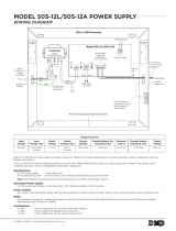
2.6 Wiring Diagram
The XR2400F system below shows the layout of the components. The wires shown in this guide have been
factory installed and connected. The dashed lines represent wires that run underneath a component.
Detailed wiring diagrams for each supplied component appear in following sections of this guide.
AC +B BELL GND SMK GND
RED YEL GRN BLK Z1 Z2 Z3 Z4 Z5 Z6 Z7 Z8 Z9+ Z9- Z10+ Z10-
AC -B GND GND GND
GND
XR2400F Command Processor™
Panel
See LT-0554, XR2400F Command Processor™
Panel section for complete XR2400F information.
J10
Output Header J2
462N LX-Bus Interface Card
J16
866
Module
#1
866
Module
#2
+-
+-
+
+-
Two 12 VDC batteries
connected in series with the
included Series Connecting
Strap. See Secondary
Power Supply section.
12 VDC
battery
12 VDC
battery
12 VDC battery
Two 12 VDC batteries
connected in parallel with a
Model 318 Dual Battery
Harness. See Secondary
Power Supply section.
504-24 Secondary Power Supply
1.5 Amps maximum charge current.
Use only 24 VDC rechargeable batteries
or Two DMP Model 367 12 VDC batteries
with a Series Connecting Strap.
Replace every 3 to 5 years.
XR2400F Secondary Power Supply
1.5 Amps maximum charge current.
Use only 12 VDC rechargeable batteries
DMP Model 367.
Replace every 3 to 5 years.
12 VDC battery
24 VDC
Circuit
Black
Red
To Fire Command Center on enclosure door
From XR2400F
panel to 12 VDC.
Black
Red
56 VA Transformer
charges 4 batteries
GREEN
WHITE
BLACK
GREEN
WHITE
BLACK
WHITE
BLACK
28 VAC
Transformer
+ DC -
+ Bat -
Red wire to positive
battery terminal. Black wire to negative
battery terminal.
AC
AC TRBL BATT TRBL
504-24
Power Supply
See LT-0554, 504-24 Power
Supply section for complete
504-24 information.
893A
P10
To Tel c o S
To Notification
Appliances
S
S
S
S
S= Supervised Wire
S
S
S
Battery
Compartment
From 504-24 Power Supply to 24 VDC.
1K EOL
1K EOL
16 VAC
Transformer
Figure 2: XR2400F System

Digital Monitoring Products XR2400F Installation Guide
4
INSTALLATION
AC Connection
3.1 Transformers and AC Power Connection
The AC connection should be completed by a licensed electrician.
Never share the Fire Alarm Control Panel circuit with any other equipment.
The XR2400F comes supplied with two transformers: the 16 VAC 56 VA transformer and the 28 VAC 175 VA
transformer. The 28 VAC and the 16 VAC transformers’ white leads and black leads must be connected
together respectively. These wires must be connected to an unswitched 120 VAC 60 Hz power source with at
least 1.85 Amps of available current.
Black wire - attach the black 120 VAC wire to the black wire of the transformers.
White wire - attach the white 120 VAC wire to the white wire of the transformers.
Green wire - attach the green wire lead to the green wire attached to the enclosure.
S
S
56 VA Transformer
charges 4 batteries.
GREEN
WHITE
BLACK
GREEN
WHITE
BLACK
WHITE
BLACK
28 VAC
Transformer
To XR2400F Panel
Violet
Terminal 1
Gray
Terminal 2
Yellow
Blue
To Model 504-24
AC Terminals
16 VAC
56 VA
Transformer
L-Bracket
Bracket
Nut
Bracket
Nut
Figure 3: Transformers and AC Power Connection
Always ground the panel before applying power to any devices! Use 18 AWG or larger for all power
connections. The XR2400F must be properly grounded before connecting any devices or applying power
to the panel. Proper grounding protects against Electrostatic Discharge (ESD) that can damage system
components.
3.2 28 VAC Transformer
The 28 VAC Transformer supplies power to the AC terminals of the 504-24 Power Supply which is factory pre-
wired to the two 866 NAC modules. The 28 VAC is located in the upper right hand corner of the enclosure
surrounded by a metal divider. See Figure 3 above and the 504-24 Power Supply section.
3.3 16 VAC Transformer
The 16 VAC 56 VA transformer supplies power to the XR2400F panel and is factory pre-wired. See Figure 3:
Transformers and AC Power Connection. Also refer to Figure 11: XR2400F Panel Wiring Diagram.
3.4 Earth Ground from the XR2400F Panel
Terminal 4 of the XR2400F panel must be connected to earth ground using 14 gauge or larger wire to provide
proper transient suppression. DMP recommends connecting to a cold water pipe or ground rod only. Do not
connect to an electrical ground or conduit, sprinkler or gas pipes, or to a telephone company ground.

XR2400F Installation Guide Digital Monitoring Products
5
INSTALLATION
Secondary Power Supply
4.1 Description
The XR2400F system includes pre-wired cables for connecting a 24 VDC battery to the 504-24 power supply
and a 12 VDC battery to the XR2400F panel. For 24 VDC battery operation to the 504-24, connect two 12
VDC sealed lead-acid batteries in series using the included series connecting strap. See Figure 4. Observe
polarity when connecting all batteries.
Use sealed lead-acid batteries only. Use the DMP Model 367, 12 VDC 7.7Ah sealed lead-acid rechargeable
battery. Batteries supplied by DMP or manufactured by Eagle Picher or Yuasa have been tested to ensure
proper charging with DMP products.
Gel cell batteries cannot be used with the XR2400F panel.
4.2 Battery Connection to XR2400F Command Processor panel
For 12 VDC battery operation to the XR2400F, connect the black battery lead to the negative terminal of the
battery. The black battery wire is connected to terminal 4 of the XR2400F panel.
Connect the red battery lead to the positive terminal of the battery. The red battery wire is connected to
terminal 3 of the XR2400F panel. See Figure 11 and Figure 2.
You can add a second battery in parallel using the DMP Model 318 Dual Battery Harness. When wiring two
batteries with the Model 318 Dual Battery Harness, plug the red male end of the Dual Battery Harness into
the red female battery lead from the panel. Plug the black male end of the Dual Battery Harness into the
black female battery lead from the panel. Attach both female leads from the Dual Wiring Harness to the
two batteries as described above. See Table 3: Battery Calculations.
4.3 Battery Connection to the 504-24 Power Supply
The 504-24 is powered by 24 VDC. After connecting two 12 VDC batteries together using the series
connecting strap (or after installing one 24 VDC battery) connect the black battery wire to the negative
terminal of the 24 VDC battery. The black battery wire is connected to the negative AC terminal of the 504-
24.
Connect the red battery wire to the positive terminal of the 24 VDC battery. The red battery wire is
connected to the positive AC terminal of the 504-24.
12 VDC
Battery
RED
BLACK
Series
Connecting
Strap
12 VDC
Battery
Figure 4: 24 VDC Battery Wiring
See Figure 9 and Figure 2. Also see the Battery Information section.

Digital Monitoring Products XR2400F Installation Guide
6
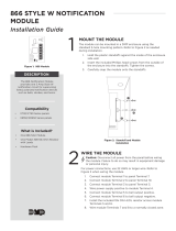
INSTALLATION
Two 866 NAC Modules
5.1 Description
Each 866 provides one style W indicating circuit for supervising UL polarized notiÞ cation appliances, such as
bells, strobes, and horns. See Table 1: NotiÞ cation Appliances for a list of approved notiÞ cation appliances.
5.2 Connection
Each 866 module is pre-installed on the removable backplate using the standard three-hole conÞ guration.
The modules are factory pre-wired to each other, the 504-24, and the XR2400F panel. Refer to the Þ gure
below and to Figure 2: XR2400F System for wiring connections.
You can connect 24 VDC NotiÞ cation Appliances to terminals 5 and 6 of each module. Each module provides
a zone of notiÞ cation and can be activated separately.
1 AUX PWR
2 GND
3 Alarm In
4 Bell PWR In
5 Bell Out +
6 Bell Out -
7 Bell Trouble
8 Bell Trouble
866
Module #1
Normal/Silence Switch
1 AUX PWR
2 GND
3 Alarm In
4 Bell PWR In
5 Bell Out +
6 Bell Out -
7 Bell Trouble
8 Bell Trouble
866
Module #1
Normal/Silence Switch
To XR2400F Output #1 (J2 pin #2)
To XR2400F terminal 13 (Zone 1)
To XR2400F terminal 7
To 504-24 DC -
To XR2400F Output #2 (J2 pin #5)
To 504-24 DC +
To XR2400F terminal 15 (Zone 2)
To 504-24 BATT TRBL C (Common)
10K EOL
DMP Model 308
UL Listed,
Polarized
Notification
Appliances
See Table 1:
Notification
Appliances
24 VDC
10K EOL
DMP Model 308
UL Listed,
Polarized
Notification
Appliances
See Table 1:
Notification
Appliances
24 VDC
Pre-installed 1K EOL
Pre-installed 1K EOL
Figure 5: 866 Modules Wiring
5.3 Bell Silence/Bell Trouble
A bell silence switch on the 866 module is provided to prevent sounding of the indicating devices when
testing the system. When the Silence position is selected, a 15-second delay occurs before the 866 bell
trouble contacts (terminals 7 and 8) open. Select the Normal position after testing to return the 866
module to normal operation.

XR2400F Installation Guide Digital Monitoring Products
7
INSTALLATION
5.4 NotiÞ cation Appliances
The following table indicates the approved notiÞ cation appliances that can be used with the XR2400F
system.
DMP Model Description
802 12/24 VDC Multi-Tone Horn
802WP-75W 24 VDC Weatherproof Multi-Tone Horn
803 12/24 VDC Standard Horn
850S Single Action Dry Contact Pull Station
850D Dual Action Dry Contact Pull Station
806-6 12 VDC 6-Inch Bell
806-10 12 VDC 10-Inch Bell
821 12 VDC Strobe
822 12 VDC Strobe with RetroÞ t Plate
823 12 VDC Horn Strobe
831 12/24 VDC Single Circuit Sync Module
832 12/24 VDC Dual Circuit Sync Module
901 24 VDC Mini Horn
904 24 VDC Horn
904WP 24 VDC Weatherproof Horn
906-6 24 VDC 6-Inch Bell
906-10 24 VDC 10-Inch Bell
921-MCW 24 VDC Multi-Candela Strobe
922-MCW 24 VDC Multi-Candela Strobe with RetroÞ t Plate
923-MCW 24 VDC Multi-Candela Horn Strobe
924-MCW 24 VDC Multi-Candela Audible Strobe
924WP-75W 24 VDC Weatherproof Audible Strobe
Table 1: NotiÞ cation Appliances

Digital Monitoring Products XR2400F Installation Guide
8
INSTALLATION
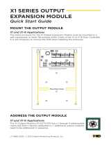
462N LX-Bus™ Expansion Card
6.1 Description
The 462N LX-Bus™ Expansion Card provides an additional 100 zones to the XR2400F.
6.2 LX-Bus™ Expansion Capability
The 462N card provides a 4-wire LX-Bus™ that allows you to connect up to 100 Model 521LX or 521LXT
Addressable Smoke Detectors. Also the LX-Bus™ could connect up to 25 Model 714, 715, and 725 Zone
Expanders or 716 Output Expanders, up to six Model 714-16 or 715-6 Zone Expanders, and up to 100 Model
711 and 711E Zone Expanders. Power for the devices is provided through the Black and Red wires of the
expansion harness.
6.3 Installing the 462N Module
1. Remove AC and battery power from the XR2400F panel before installing the 462N card.
2. Align the 50 pin connector of the 462N with the J6 connector on the XR2400F panel.
3. Press the 462N onto the J6 connector while applying even pressure to both sides.
XR2400F Panel
J6 Expansion
Connector
462N Network
Interface Card
Configuration
Jumpers
B
Red - Aux. Positive Red
Y
ellow - Serial Data In Yellow
Green - Serial Data Out Green
Black - Aux. Common Black
To LX-Bus Modules
LX-Bus
Connector
Figure 6: 462N Wiring

XR2400F Installation Guide Digital Monitoring Products
9
INSTALLATION
Telephone RJ Connector
7.1 Description
Connect the XR2400F system to two lines of the public telephone network by installing two DMP 356 RJ
Cables between the RJ31X or RJ38X phone jacks, and the 893’s J4 connector (for main line) and J5 (for
backup line). Set the 3-pin headers on the XR2400F labeled J11 and J12 to DD for digital dialer, Contact ID,
or Modem IIe operation. See 893A Dual Phone Line Module.
Figure 7: Phone Jack Wiring
To Telephone
Line
RJ31X or RJ38X
Phone Block
8
7
6
54
3
2
1
Ring Tip
To Premise
Phone
Ring 1 Tip 1
7.2 FCC registration
The Model XR200/XR2400F complies with FCC part 68 and is registered with the FCC. Registration number:
CCKUSA-18660-AL-R / Ringer Equivalence: 1.1B
7.3 NotiÞ cation
Registered terminal equipment must not be repaired by the user. In case of trouble, the device must be
immediately unplugged from the telephone jack. The factory warranty provides for repairs. Registered
terminal equipment may not be used on party lines or in connection with coin telephones. No tiÞ cation must
be given to the telephone company of:
a. The particular line(s) the service is connected to (the speciÞ c phone line)
b. The FCC registration number (CCKUSA-18660-AL-R)
c. The ringer equivalence (1.1B)
d. The make, model, and serial number (see the serial # sticker on the panel) of the device
7.4 Ground start
Ground start phone service cannot be used on commercial or residential Þ re applications.

Digital Monitoring Products XR2400F Installation Guide
10
INSTALLATION
893A Dual Phone Line Module
8.1 Description
The 893A is a dual telephone line supervision module that allows the panel to indicate a phone line failure
to the premises and the central monitoring station. After the 893A senses a failure on the main line, it
switches to the backup, or secondary, phone line. The 893A is installed on the removable backplate above
the XR2400F circuit board.
8.2 Connection
The 893A connects the panel to the public telephone network by installing a DMP 356 RJ Cable between the
XR2400F panel’s J3 connector and the 893’s J3 connector labeled PANEL. The two communication jumpers
must be set to either DD or MPX.
J2 DD
MPX
J1
DD
MPX
J3
PANEL
J4
MAIN
J5
BACKUP
P10
Factory pre-wired
to XR2400F panel
Phone Jack
Connector, J3
To Primary
telephone line
To Secondary telephone line
Communication Jumpers: Both
Jumpers must be set
Processor
Stopped Buzzer
Factory pre-wired
to XR2400F panel
J10 Connector
893A Dual Telephone Line Module
Figure 8: 893A Dual Phone Line Module Wiring
8.3 Jumper Settings
There are two sets of jumpers on the 893A module. When setting the module for either DD (digital dialer) or
MPX (multiplex), both jumpers must be set.
8.4 Digital Dialer/Multiplex
You can conÞ gure the 893A to provide two lines of digital dialer or one line of multiplex with digital dialer
backup. For multiplex operation both jumpers (J1 and J2) must be set to MPX. Also, jumpers J11 and J12 on
the panel must be set to MPX. See XR2400F Command Processor Panel Connection. The XR2400F is preset
at the factory for Digital Dialer. The Main modular jack (J4) is used for the primary dialer or multiplex line.
The Backup modular jack (J5) is used for the secondary digital dialer line.
8.5 Phone Line Monitor
The 893A uses a phone line monitor for the main and backup phone lines. When sending a report, the 893A
veriÞ es the main phone line is working before sending. If the line is bad, the module tests the backup phone
line. The 893A sends the report on the Þ rst working phone line.
The phone line monitor has a 2-minute trouble delay and a 1-minute restore delay. Phone line trouble is
displayed in the Fire Command Center LCD Status List as a System Trouble. The Fire Command Center LCD is
factory programmed to display system troubles in the Status List.
8.6 Processor Fail Buzzer
The 893A module also monitors the panel’s CPU and sounds a trouble buzzer whenever either the panel’s
processor is reset using J16 or the processor stops functioning.

XR2400F Installation Guide Digital Monitoring Products
11
INSTALLATION
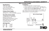
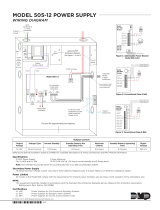
504-24 Power Supply
9.1 Description
The 504-24 is a power limited, switching power supply that meets UL, CSFM, NFPA, and FCC compliance
standards. Model 504-24 is rated for 24 VDC @ 4 Amps maximum and supplies power to the 866 Modules.
9.2 LED’s
The 504-24 has two status LED’s that show the current state of power. The green LED indicates low AC
input. The red LED indicates low standby battery power after AC has failed.
9.3 504-24 Condition Chart
Condition Voltage Levels LED Status Condition
AC Trouble Approx. 102 VAC AC LED (Green) On AC Good
Battery Trouble Below 23.6 VDC AC LED (Green) Off AC Bad
Battery Restoral Above 25.0 VDC DC LED (Red) On Battery Good
Battery Cutoff Below 20.4 VDC DC LED (Red) Off Battery Bad
Table 2: 504-24 Condition and LED Indicators
9.4 504-24 UL Listings
For UL 603 Power Supplies for Burglary Alarm Systems and UL 294 Power Supplies for Access Control System
applications: Voltage Range of 22.9 to 25.5 VDC.
For UL 1481 Power Supplies for Fire Protective Signaling the following maximum battery standby Ampere
hours apply for 24 hours of battery backup:
Battery Standby Maximum: 49.2Ah
Output Voltage: 24 VDC
Output Current: 1.5A standby, 4 Amp alarm
9.5 24 VDC NAC Standby Battery Calculations
The following calculation deÞ nes the total number of standby battery Amp-hours required to support
operation of the NACs and any other devices attached to the 504-24 power supply. From this calculation,
assemble the appropriate number of batteries that will just exceed the calculated total Amp-hour
requirement. The 866 NACs receive power for internal operation from the XR2400F panel and do not enter
in this calculation themselves.
1. Add all standby current values including the power supply operating current.
2. Multiply the total standby current by the number of standby hours needed.
3. Add all alarm current values from the notiÞ cation appliances attached to the 866 NACs and multiply by
0.25.
4. Add the total alarm mA-hour with the total standby mA-hour and then multiply this number by 0.001.
Power Supply Operating Current 200 mA
Other Standby Current + ______ mA
1. Total Standby Current + ______ mA
Number of Standby Hours Required X ______ hr
2. Total Standby (mA-hr) Required = ______ mA-hr
3. Total Alarm Current = ______ mA
Total Alarm Current X 0.25 = ______ mA-hr
(0.25 = 5 minutes in alarm)
Total Standby (Required) + ______ mA-hr
Total = ______ mA-hr
X 0.001
4. Total Required Amp-hours = ______
Table 3: Battery Calculations

Digital Monitoring Products XR2400F Installation Guide
12
INSTALLATION
9.6 Connection
The 24 VDC power supply is completely pre-wired. Refer to the following 504-24 wiring diagram for speciÞ c
wire connections.
+ DC -
+ Bat -
Red wire to positive
battery terminal.
Black wire to negative
battery terminal.
AC
AC TRBL BATT TRBL
504-24 Power Supply To XR2400F Panel
terminal 10 (BLK)
To 866 Module #2
terminal 2 (GND)
To 866 Module #2
terminal 4 (Bell PWR In)
NC C NO NC C NO
To 866 Module #2
terminal 8 (BELL TRBL)
To XR2400F Panel
terminal 18 (Zone 4)
To XR2400F Panel
terminal 16 (Zone 3)
Both wires to
28 VAC
Transformer
AC
Green
LED
DC
Red
LED
Yellow
Blue
Green
Green
Black
Black
Red
Black
Black
White/Red
Figure 9: 504-24 Wiring
Interconnect Wiring Harness
10.1 Interconnect Harness
This chart explains the colors of the wires on the Interconnect Wiring Harnesses. It also explains what each
wire connects.
Wire Color Connection From Connection To
Red Panel Terminal 7 (DC Power) 866 Module #2 Terminal 1 (Auxiliary Power)
Black Panel Terminal 10 (Common) 504-24 DC - Negative DC Terminal (Ground)
Brown Panel Terminal 13 (Zone 1) 866 Module #1 Terminal 7 (Bell Trouble)
Violet Panel Terminal 15 (Zone 2) 866 Module #2 Terminal 7 (Bell Trouble)
Green Panel Terminal 16 (Zone 3) 504-24 Battery Trouble Terminal N/O
White Panel Terminal 18 (Zone 4) 504-24 AC Trouble Terminal N/C
Blue Panel J2 Pin 2 (Common) 866 Module #1 Terminal 3 (Alarm In)
Orange Panel J2 Pin 3 (Output 1 N/O) Panel Terminal 5 (Bell Output)
Yellow Panel J2 Pin 5 (Common) 866 Module #2 Terminal 3 (Alarm In)
Orange Panel J2 Pin 6 (Output 2 N/O) Panel Terminal 5 (Bell Output)
White/Red 504-24 DC + (Positive DC Terminal) 866 Module #2 Terminal 4 (Bell Power In)
Black 504-24 DC - (Negative DC Terminal) 866 Module #2 Terminal 2 (Ground)
Red 866 Module #2 Terminal 1 (Auxiliary Power) 866 Module #1 Terminal 1 (Auxiliary Power)
Black 866 Module #2 Terminal 2 (Ground) 866 Module #1 Terminal 2 (Ground)
Black 866 Module #2 Terminal 2 (Ground) 866 Module #1 Terminal 8 (Bell Trouble)
White/Red 866 Module #2 Terminal 4 (Bell Power In) 866 Module #1 Terminal 4 (Bell Power In)
Black 866 Module #2 Terminal 8 (Bell Trouble) 504-24 Battery Trouble Common Terminal
Black 866 Module #2 Terminal 8 (Bell Trouble) 866 Module #1 Terminal 8 (Bell Trouble)
Table 4: Interconnect Wiring Harness
/