Page is loading ...

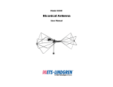
Model 3158
High Power
Biconical Antenna
User Manual
Model 3158 shown with optional pedestal Model 113870 (sold separately)

ii |
ETS-Lindgren L.P. reserves the right to make changes to any product described
herein in order to improve function, design, or for any other reason. Nothing
contained herein shall constitute ETS-Lindgren L.P. assuming any liability
whatsoever arising out of the application or use of any product or circuit
described herein. ETS-Lindgren L.P. does not convey any license under its
patent rights or the rights of others.
© Copyright 2000–2016 by ETS-Lindgren L.P. All Rights Reserved. No part
of this document may be copied by any means without written permission
from ETS-Lindgren L.P.
Trademarks used in this document: The ETS-Lindgren logo and FACT are
trademarks of ETS-Lindgren L.P.
Revision Record
MANUAL, MODEL 3158 HIGH POWER BICON | Part #399262, Rev. E
Revision Description Date
A Initial Release December, 2000
B Updates / edits March, 2002
C Updated Assembly and Mounting
Instructions; Rebrand
February, 2009
D Updated data; updated photos May, 2009
E Updated pedestal information March, 2016

| iii
Table of Contents
Notes, Cautions, and Warnings ................................................ v
Safety Information ..................................................................... v
1.0 Introduction .......................................................................... 7
ETS-Lindgren Product Information Bulletin ................................................... 8
2.0 Maintenance ......................................................................... 9
Annual Calibration ......................................................................................... 9
Maintenance of Fiber Optics .......................................................................... 9
Service Procedures ..................................................................................... 10
3.0 Specifications ..................................................................... 11
Electrical Specifications ............................................................................... 11
Physical Specifications – Antenna Only ...................................................... 11
Physical Specifications – Pedestal (sold separately) ................................... 11
4.0 Assembly and Mounting Instructions .............................. 13
5.0 Typical Data ........................................................................ 17
Data from MIL-STD-461F/RTCA DO-160 Setup (No Bench) ...................... 17
MIL-STD-461F/RTCA DO-160 Setup (No Bench) ............................... 18
Data from ISO 11451-2 Setup ..................................................................... 19
ISO 11451-2 Setup .............................................................................. 20
Data from ECE Regulation 10 Setup ........................................................... 21
Appendix A: Warranty ............................................................. 23

iv |
This page intentionally left blank.

| v
Notes, Cautions, and Warnings
Note: Denotes helpful information intended to provide tips for
better use of the product.
Caution: Denotes a hazard. Failure to follow instructions
could result in minor personal injury and/or property
damage. Included text gives proper procedures.
Warning: Denotes a hazard. Failure to follow instructions
could result in SEVERE personal injury and/or property
damage. Included text gives proper procedures.
See the ETS-Lindgren Product Information Bulletin for safety,
regulatory, and other product marking information.
Safety Information
Refer to Manual: When product is marked with this
symbol, see the instruction manual for additional
information. If the instruction manual has been misplaced,
download it from www.ets-lindgren.com, or contact
ETS-Lindgren Customer Service.
High Voltage: Indicates presence of hazardous voltage.
Unsafe practice could result in severe personal injury or
death.

vi |
High Voltage: Indicates presence of hazardous voltage.
Unsafe practice could result in severe personal injury or
death.
Protective Earth Ground (Safety Ground): Indicates
protective earth terminal. You should provide
uninterruptible safety earth ground from the main power
source to the product input wiring terminals, power cord,
or supplied power cord set.
Laser Warning: Denotes a laser (class 1M) is part of the
operating system of the device.
Waste Electrical and Electronic Equipment (WEEE)
Directive: (European Union) At end of useful life, this
product should be deposited at an appropriate waste
disposal facility for recycling and disposal. Do not
dispose of with household waste.
Recyclable Products: This product includes rechargeable
batteries. At end of useful life, please recycle the used
batteries, or dispose of them safely and properly. Many
cities collect used batteries for recycling or disposal. You
may contact your local waste disposal agency for
information on battery recycling and disposal.

7 | Introduction
1.0 Introduction
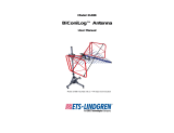
The ETS-Lindgren Model 3158 High Field Biconical Antenna is specifically
designed for Immunity testing.
This linearly-polarized
transmit antenna is
optimized to generate
high levels of
electromagnetic fields in
the range of 20 MHz to
120 MHz.
Model 3158
shown with optional pedestal
Model 113870 (sold separately)
The ability of the Model 3158 to handle high power levels over a broadband
makes it excellent for use in Radiated Susceptibility testing.
The biconical elements are made from welded aluminum tubing. The 4-to-1 ratio
balun network is fabricated from G10 fiberglass and specially machined brass
and aluminum support and contact parts. The bifilar inductors of the balun are
wound in precision-machined cuts to provide high barrier insulation between
windings while simultaneously giving good coupling between bifilar windings.
During manufacturing each Model 3158 is individually calibrated using the
three antenna method of calibration. The results of the calibration are tabulated
and included with the antenna.

Introduction | 8
ETS-Lindgren Product Information Bulletin
See the ETS-Lindgren Product Information Bulletin included with your shipment
for the following:
Warranty information
Safety, regulatory, and other product marking information
Steps to receive your shipment
Steps to return a component for service
ETS-Lindgren calibration service
ETS-Lindgren contact information

9 | Maintenance
2.0 Maintenance
Before performing any maintenance,
follow the safety information in the
ETS-Lindgren Product Information
Bulletin included with your shipment.
Maintenance of the Model 3158 is limited
to external components such as cables
or connectors.
If you have any questions concerning
maintenance, contact ETS-Lindgren
Customer Service.
Annual Calibration
See the Product Information Bulletin included with your shipment for information
on ETS-Lindgren calibration services.
Maintenance of Fiber Optics
Fiber optic connectors and cables can be damaged from airborne particles,
humidity and moisture, oils from the human body, and debris from the connectors
they plug into. Always handle connectors and cables with care, using the
following guidelines.
WARRANTY

Maintenance | 10
Before performing any maintenance, disconnect
the fiber optic cables from the unit and turn off
power.
When disconnecting fiber optic cables, apply
dust caps to the ends to maintain their integrity.
Before connecting fiber optic cables, clean the
connector tips.
Before attaching connectors, clean them with
moisture-free compressed air.
Failure to perform these tasks may result in
damage to the fiber optic connectors or cables.
Service Procedures
For the steps to return a system or system component to ETS-Lindgren for
service, see the Product Information Bulletin included with your shipment.

11 | Specifications
3.0 Specifications
Electrical Specifications
Frequency Range: 20 MHz to 120 MHz
VSWR Ratio:
Typical—2:1
Maximum—5:1
Maximum Input Power: 5 kW
Input Impedance: 50 Ω
Connector: 7/16 DIN female
Physical Specifications – Antenna Only
Length: 1.14 m (3.74 ft)
Width: 3.00 m (9.84 ft)
Height: 1.14 m (3.74 ft)
Physical Specifications – Pedestal (sold separately)
Length: 1.73 m (5.68 ft)
Width: 1.52 m (5.00 ft)
Height: 2.51 m (8.23 ft)
Tilt Range: 0° to 45°

Specifications | 12
This page intentionally left blank.

13 | Assembly and Mounting Instructions
4.0 Assembly and Mounting Instructions
Before connecting any components, follow the
safety information in the ETS-Lindgren
Product Information Bulletin included with your
shipment.
Optional Pedestal
(sold separately)

Assembly and Mounting Instructions | 14
The Model 3158 High Power Biconical Antenna is shipped unassembled, and
includes these parts:
Balun
Biconical element (2)
Belleville washer (2)
Washer (4) and 5/16–1 1/4 hex bolt (4)
Air solenoid nylon tube
Fiber optic polarization cable
An optional pedestal, Model 113870, is sold separately
Due to the size of the antenna, you must mount the balun onto the
pedestal before you attach the elements.
1. Run your antenna cable through the polarization tube and attach it to
the connector on the bottom of the balun.

15 | Assembly and Mounting Instructions
2. Place the bottom of the balun in the mount plate. Insert two washers
and two hex bolts on both sides of the mount plate to firmly secure the
balun in place.
Do not cross thread any connections or permanent
damage could occur.
3. Slide a belleville washer onto the threaded screw end of one of the
biconical elements.
4. Line up the screw threads on the element with the receptacle hole on
the balun and turn the element until it is firmly secured in the balun.
5. Repeat step 3 and step 4 for the remaining biconical element.
Damage to the pneumatic system may occur if the air
supply exceeds the maximum 50 psi–70 psi.
6. Connect the air solenoid tube to the air solenoid located on the back of
the pedestal. Connect the other end to your air supply.
The Model 2090 (or next generation ETS-Lindgren controller, if
applicable) is a separate component required for operation.
7. Connect the fiber optic polarization cable to the polarization unit
located on the back of the pedestal. Connect the other end to the
Model 2090 Multi-Device Controller.

Assembly and Mounting Instructions | 16

17 | Typical Data
5.0 Typical Data
All data was measured in an ETS-Lindgren FACT™ 3 chamber; field for
a 5-kW input.
Data from MIL-STD-461F/RTCA DO-160 Setup (No Bench)

Typical Data | 18
MIL-STD-461F/RTCA DO-160 SETUP (NO BENCH)
Shown with optional pedestal Model 113870 (sold separately).

19 | Typical Data
Data from ISO 11451-2 Setup

Typical Data | 20
ISO 11451-2 SETUP
Shown with optional pedestal Model 113870 (sold separately).
/