76
Tripod Options
ETS-Lindgren offers the following non-metallic, non-reflective tripods for use
at both indoor and outdoor EMC test sites.
ETS-Lindgren Product Information Bulletin
See the ETS-Lindgren Product Information Bulletin included with your
shipment for the following:
• Safety, regulatory, and other product marking information
• Steps to receive your shipment
• Steps to return a component for service
• ETS-Lindgren calibration service
• ETS-Lindgren contact information
Note:
For easy horizontal and
vertical polarization,
the ETS-Lindgren
Model 7-TR tripod is
recommended.
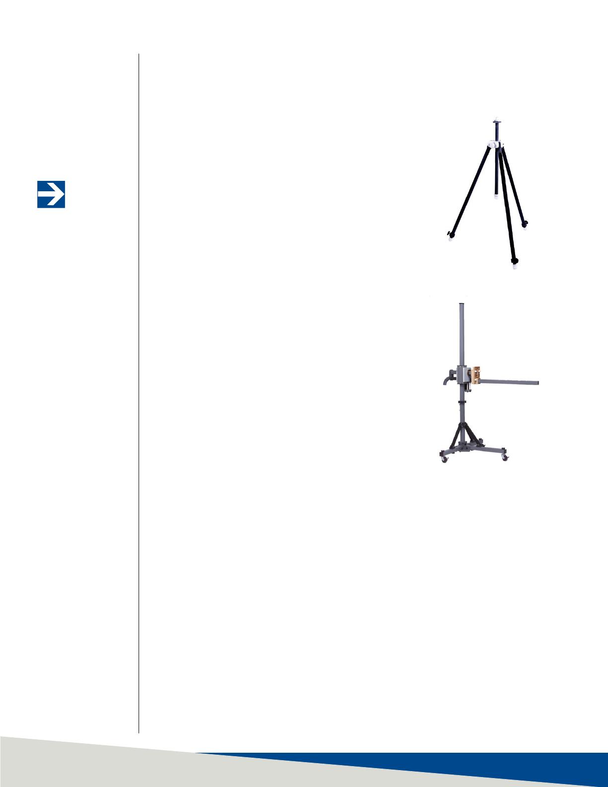
• 4-TR Tripod—Constructed of linen phenolic
and delrin, designed with an adjustable
center post for precise height adjustments.
Maximum height is 2.0 m (80.0 in), and
minimum height is 94 cm (37.0 in). This tripod
can support up to an 11.8 kg (26.0 lb) load.
• 7-TR Tripod—Constructed of PVC and
fiberglass components, providing increased
stability for physically large antennas. The
unique design allows for quick assembly,
disassembly, and convenient storage. Allows
several different configurations, including
options for manual or pneumatic polarization.
Quick height adjustment and locking wheels
provide ease of use during testing. Maximum
height is 2.17 m (85.8 in), with a minimum
height of 0.8 m (31.8 in). This tripod can
support a 13.5 kg (30 lb) load.