Page is loading ...

Introduction | 1
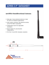
Model 3159C
High-Power
Biconical Antenna
User Manual

2 | Introduction

Introduction | 3
ETS-Lindgren Inc. reserves the right to make changes to any products herein to improve functioning or design. Although
the information in this document has been carefully reviewed and is believed to be reliable, ETS-Lindgren does not
assume any liability arising out of the application or use of any product or circuit described herein; nor does it convey any
license under its patent rights nor the rights of others. All trademarks are the property of their respective owners.
© Copyright 2005–2020 by ETS-Lindgren Inc. All Rights Reserved. No part of this document may be copied by
any means without written permission from ETS-Lindgren Inc.
Trademarks used in this document: The ETS-Lindgren logo is a trademark of ETS-Lindgren Inc.
Revision Record
MANUAL,3159C HIGH POWER BI-CONICAL ANT | Part #399775, Rev. E
Revision Description Date
A Initial Release November, 2005
B Rebrand November, 2008
C Update specifications February, 2018
D Update specifications, add
extension information
July, 2020
E Update information on variations SeptemberOctober,
2020

4 | Introduction
Table of Contents
Notes, Cautions, and Warnings ............................................... 5
1.0 Introduction .......................................................................... 6
ETS-Lindgren Product Information Bulletin ................................................... 7
2.0 Maintenance ......................................................................... 8
Annual Calibration ......................................................................................... 8
Replacement Parts ........................................................................................ 8
Service Procedures ....................................................................................... 8
3.0 Specifications ...................................................................... 9
Electrical Specifications ................................................................................. 9
Physical Specifications .................................................................................. 9
Model 3159C Antenna ........................................................................... 9
Model 3159C Pedestal .......................................................................... 9
Ferrite Floor ......................................................................................... 10
4.0 Mounting Instructions ....................................................... 11
Mounting the Balun and Polarization Unit .................................................... 11
Mounting the Biconical Elements ................................................................. 12
Adjusting the Tube Extensions .................................................................... 12
Removing the Connector ............................................................................. 13
5.0 Operation ............................................................................ 14
Model 3159C Pedestal ................................................................................ 14
Electrical Field Distribution .......................................................................... 14
Performance ................................................................................................ 15
Typical Calibration Data ............................................................................... 19
Typical Antenna Factor at 6M .............................................................. 19
Calculated Forward Power at 3.5M ..................................................... 19
Balun VSWR ........................................................................................ 20

Introduction | 5
Notes, Cautions, and Warnings
Note: Denotes helpful information intended to
provide tips for better use of the product.
Caution: Denotes a hazard. Failure to follow
instructions could result in minor personal injury
and/or property damage. Included text gives proper
procedures.
Warning: Denotes a hazard. Failure to follow
instructions could result in SEVERE personal injury
and/or property damage. Included text gives proper
procedures.
See the ETS-Lindgren Product Information Bulletin for safety,
regulatory, and other product marking information.

6 | Introduction
1.0 Introduction
The ETS-Lindgren Model 3159C High-Power Biconical Antenna is a broadband, linearly polarized biconical antenna
with a 20 MHz to 100 MHz frequency range. This antenna exhibits a wide beamwidth and is designed to continuously
handle up to 10 kW input power for generating high electric field strength over a large uniform area.
The pedestal is assembled with two fixed and two freewheeling casters that allow the antenna position on the test range
to be easily adjusted, or rolled into or out of the chamber for storage when not in use. The dual mast features regularly
spaced mounting holes so that the height of the boom can be adjusted. Slots below the base allow for easy transport with
a pallet jack or forklift. Horizontal and vertical polarization rotation is performed by a toggle switch on the back. The air
valve assembly for pneumatic polarization is mounted on the mast. The base is a steel plate covered in 137 ferrite tiles.
Each tile has a 10 mm hole in its center.
Unlike the top hat, capacitive-loaded, log periodic dipole antenna normally used in this frequency range, the phase
center/source distance is the same for low and high frequencies. This ensures high field strength at frequencies as low as
20 MHz. The design of the Model 3159C takes advantage of the wide beamwidth feature of a biconical antenna. In
addition, the optimized design provides low VSWR and high radiation efficiency.
The 3159 was developed to support high field strength immunity measurements in anechoic chambers of varying sizes.
Versions of this antenna have been used in various sized chambers from those small enough to support the ISO 11452-2
component testing, up to full sized chambers with at least 8 m of clear internal height, large enough to support ISO 11451-
2 vehicle testing.
The BiConical antennas of different sizes are broadband adaptations of a half wave dipole antenna optimized for use in
the 20 MHz to 300 MHz frequency range. Over this range, they are still electrically very short. To overcome this limitation
in radiation efficiency, there are several variants of the 3159 antenna, each designed to optimize the antenna performance
based on the available space and test distance, with the available amplifier power used to estimate the best case
performance.
The standard
configuration for the
Model 3159C consists of:
Two open-end
adjustable biconical
elements
High-power balun
Pedestal with casters
and polarization
control
Two Biconical
elements
(shown with
extensions)
Pneumatically
assisted
polarization
cylinder
Casters
Balun unit
Ferrite floor

Introduction | 7
All current variants of the 3159 antenna with different element arrangements feature a 10kW balun. In the current version
C design, the balun is an air-cooled 4:1 Guanella transformer, with upgraded corona and tracking breakdown protection
over previous versions. There are six pairs of removable sections with included sections; the complete set consists of twelve
1.74 m long sections with up to two 0.5 m extensions (per element), which can be used for a maximum element length of
2.74m (Figure 1).
Figure 1: Overall dimensions of 3159C Antenna
The antenna can be assembled and used to its maximum power rating with the twelve 1.74m long elements as a
minimum, and any symmetrical combination of the extensions. The additional 0.5m extensions can help reduce the
VSWR and improve the gain of the antenna at the low frequency end of is operation, but can increase the VSWR at other
frequencies depending on the chamber layout and proximity to other structures. The lower VSWR increases the forward
power that can be delivered to the antenna, which could improve the measured field strength.
The extensions should therefore only be used to fine-tune the performance of the antenna, with the benefit of
measurement data taken in the actual operating chamber with a representative setup.
ETS-Lindgren Product Information Bulletin
See the ETS-Lindgren Product Information Bulletin included with your shipment for the following:
Safety, regulatory, and other product marking information
Steps to receive your shipment
Steps to return a component for service
ETS-Lindgren calibration service
ETS-Lindgren contact information

8 | Maintenance
2.0 Maintenance
Before performing any maintenance, follow the safety information in the
ETS-Lindgren Product Information Bulletin included with your shipment.
Maintenance of the Model 3159C is limited to external components such as
cables or connectors.
If you have any questions concerning maintenance, contact ETS-Lindgren
Customer Service.
Check all screws periodically and tighten any that are loose.
Check the air filters weekly; more often, as necessary. The air used to feed the cylinder must be free of dirt and
moisture. Never allow the air filters to fill with water.
Lubricate all O-rings and pistons at 18-month intervals to prevent excessive wear. The air cylinder uses a
special O-ring lubricant that can be purchased from any seal or bearing store or from ETS-Lindgren.
Annual Calibration
See the Product Information Bulletin included with your shipment for information on ETS-Lindgren calibration services.
Replacement Parts
ETS-Lindgren may substitute a similar part or new part number with the same functionality for
another part/part number. Contact ETS-Lindgren for questions about part numbers and
ordering parts.
Following are the part numbers for ordering replacement parts for the Model 3159C High-Power Biconical Antenna.
Part Description Part Number
High-Power Biconical Antenna 3159C
Mast 109620
Polarization Unit (on 109620) 1718301
1 5/8 EIA Connector 675283
Element, Tube, Main 118514
Element, Tube, Half Meter Extension 118515
Bolt, M8 x 25, Hex, SS 930732
Washer, M8, Lock, Split, SS 930037
Service Procedures
For the steps to return a system or system component to ETS-Lindgren for service, see the Product Information Bulletin
included with your shipment.
WARRANTY

Specifications | 9
3.0 Specifications
Electrical Specifications
Frequency: 20 MHz–100 MHz
Input Impedance: 50 Ω
VSWR:
Typical—2:1
Maximum—4:1
Average RF Input Power: 10 kW
Maximum RF Input Power: 15 kW
RF Connector: 1 5/8 in EIA flange
Physical Specifications
MODEL 3159C ANTENNA
Length: 5.4 m (17.7 ft)
Length without extension: 3.6 m (11.8 ft)
Length with one extension: 4.5 m (14.8 ft)
Length with both extensions: 5.4 m (17.7 ft)
Diameter: 2.4 m (7.9 ft)
Weight without extensions: 12.7 kg (28 lbs)
Weight with one extension: 14.06 kg (31 lbs)
Weight with both extensions: 15.42 kg (34 lbs)
M
ODEL 3159C PEDESTAL
Length: 4.47 m (14.7 ft)
Width: 160 cm (63 in)
Total height with antenna: 6.52 m (21.42 ft)
Weight (without antenna): 272.16 kg (600 lbs)
Air Pressure Required: 80–120 PSI

10 | Specifications
FERRITE FLOOR
Length: 130 cm (51.18 in)
Width: 150.01 cm (59.06 in)
Individual tiles:
100 mm x 100 mm x 6.7 mm
(3.94 in x 3.94 in x 0.26 in)
Weight: 113.40 kg (250 lbs)

Mounting Instructions | 11
4.0 Mounting Instructions
Before connecting any components, follow the
safety information in the ETS-Lindgren
Product Information Bulletin included with your
shipment.
Do not cross thread connections or permanent damage could occur.
Mounting the Balun and Polarization Unit
Due to the size of the Model 3159C biconical elements, you must
mount the balun unit onto the pedestal prior to attaching the elements.
1. Align mounting channels to pedestal and fasten with stud and nuts to mounting plates at desired mounting
height. Use included phenolic bolts and nuts and tighten to 8ft-lbs (10.8Nm) torque
2. Align mounting holes on Polarization unit with top slotted holes on top slotted holes
3. Align balun to mounting channels and insert through bolts from behind balun rear plate, secure with lock
washer, and hex nut.
Insert spacer between polarizer and boom arm.
Insert threaded stud and tighten with hex nut to
secure.
Align the four (4) mounting holes on balun base
with four holes on boom; then insert steel bolts
and secure with steel split washers and hex
nuts. Tighten nuts to 36 ft-lbs (48Nm)

12 | Mounting Instructions
Mounting the Biconical Elements
1. Once the balun unit is securely
connected to the boom, align the
threads on one of the biconical
elements with the receptacle on
the end of the balun, and then
turn the biconical element until it
is firmly seated in the balun.
2. Tighten bolt to secure element.
3. Repeat steps for the remaining biconical element.
4. Once both elements are connected, attach the input RF coaxial cable to the connector on the rear face of the balun.
Adjusting the Tube Extensions
Each side has six (6) main tubes each with two (2), 0.5m long screw on extensions.
1. To add and adjust the extensions, screw them onto the elements.
2. To remove the extensions, unscrew them from the elements.
3. Extensions must be added to both elements so that the antenna remains symmetrical.
As an added precaution fit high visibility tape or caps to the ends of the elements when
the antenna is in the horizontal position.
Element Extensions
Insert element
into balun socket
Tighten bolt to secure element to 236 in-lbs
(26Nm)

Mounting Instructions | 13
Removing the Connector
Each side has six (6) main tubes each with two (2), 0.5m long screw on extensions.
1. Remove the four (4) mounting bolts on the flange.
2. Pull the connector firmly out of the brass yoke.
3. Plug the connector into the yoke and replace the mounting hardware (hex bolt 930732 and lock washer
930037).
Mounting Bolts
Plug connector

14 | Operation
5.0 Operation
Before connecting any components or
operating the Model 3159C, follow the safety
information in the ETS-Lindgren
Product Information Bulletin included with your
shipment.
The Model 3159C High-Power Biconical Antenna has a 4:1 Guanella balun for matching the impedance to the amplifier.
The balun maintains a low operating temperature due to the efficient radiation pattern and high power design.
Model 3159C Pedestal
To prevent damage to the cables, you must
disconnect the RF cables from the Model 3159C
before polarization or movement of the
boresight feature.
The Model 3159C pedestal has one air cylinder that controls the polarization movement of the antenna. The switch on the
back of the pedestal toggles air control. Boresight adjustment is accomplished manually by loosening the four mounting
screws so that the polarization unit can be tilted.
Electrical Field Distribution
The Model 3159C may be used for both horizontal and vertical polarization. It exhibits a dipole-like radiation pattern; for
example, a toroidal shape with an omnidirectional pattern in the H-plane. In a low frequency range such as 30 MHz
(wavelength l = 10 m), the equipment under test (EUT) is in the near field of the antenna, allowing the antenna to behave
as a field generator.

Operation | 15
Performance
The free space far field performance of the 3159 is very different to its performance in the near field semi-anechoic
chamber environment under which it typically operates. In the EMC chamber there is more coupling to the chamber floor
and the DUT which loads the antenna and could result in undesirable resonance effects that increase the VSWR of the
antenna despite the isolating benefits of the balun.
The VSWR of the antenna provides a good indication of expected performance but the actual measured Ē field strength
under test conditions in the chamber will be the most accurate. The antenna balun is manufactured and measured
separately as a preliminary performance test, with a 200 Ohm resistor placed across the output of the balun in place of
the elements. The VSWR plot shown in Figure 2, is an example of such a measurement of a version C balun, takenduring
factory calibration. Following successful completion of the balun assembly, the VSWR measurement was repeated on an
OATS with the antenna elements fitted. The antenna was mounted horizontally with the balun at 1.5m above the OATS
without ferrite tiles below the antenna. The measurement was performed with and without the full complement of
extensions for comparison. (See Figure 3.)
Figure 2: VSWR Measurement of the balun with 200 ohm load resistors
Figure 3: VSWR of antenna with and without extensions, Horiz.,no ferrites, on OATS
Without
extensions
With
extensions

16 | Operation
The performance of the 3159 antenna in a SAC depends on several factors. These include the overall size of the
chamber, the effectiveness of the absorber treatment on all surfaces, especially those close to the antenna and the
ground, height above the ground and size of the ferrite layout (if used) below the antenna. The variation in the VSWR
performance can be seen in the following three examples of installations of the 3159 in chambers of various sizes, with
different absorber treatments.
The chamber example shown in Figure 4 shows the effect of the 3159 antenna positioned at heights of 2.3 m and 3.3 m
above a large ferrite grid on the chamber floor. The antenna is being used to illuminate a large DUT. In this installation the
antenna was mounted on a custom driven positioner, with metallic structural components, which were known to impact
antenna performance at the upper frequencies
In the Figure 5 installation, the antenna is positioned at a height of 2 m above a ferrite grid in a fairly standard sized full
vehicle 10 m EMC chamber.
In the Figure 6 installation, the antenna is positioned at a height of 2 m and at a distance of 2 m from the field probe above
a reflective ground plane. As can be seen from the measurements, the trends in the measured VSWR changes with
installation conditions, since most test installations will be different from an ideal far field setup, it is expected that there
could be significant deviations from ideal antenna performance.
The E-field performance of the antenna should be measured as part of the installation setup. The plots below show some
of the variations seen in EMC installations where ferrite tiles were positioned below the antenna, and with a reflective
ground. Figure 7 shows the performance of the antenna with the full set of extensions when positioned in a small 3m
chamber and 7kW transmit power, with and without ferrites below the antenna. Figure 8 shows the same antenna in the
same chamber with the ferrite grid below the antenna but without the extension elements. This setup most closely
resembles the use of the antenna in a small EMC chamber.
Figure 4: Measured VSWR in a very large SAC at 2.3m and 3.3m height above ferrites tiles

Operation | 17
1.5m height, 1m distance,
Figure 5: Measured VSWR in 10m EMC chamber at 1.5m height above ferrite tiles
Figure 6: Measured VSWR in a very large SAC at 2.3m and 3.3m height above ferrite

18 | Operation
Figure 7: Measured Ē field in a small EMC chamber with and without ferrite on floor
Figure 8: Measured Ē field in small EMC chamber at 2.3m height above ferrite tiles

Operation | 19
Typical Calibration Data
TYPICAL ANTENNA FACTOR AT 6M
CALCULATED FORWARD POWER AT 3.5M
A calculation was used to derive the forward power data once the six-meter calibration was complete. The following
equation was used to determine the power required to generate the desired field strength at a given distance when
antenna factors are known:
𝑃 𝑑𝐵
𝑊
20 log 10 [E desired (V/m)]
20 log 10 𝑑𝑚
20 log 10 𝑓𝑀𝐻𝑧
𝐴𝐹 𝑑𝐵
𝑚1
15
With this equation, you can calculate the forward power needed to generate 100 V/m at a given distance. Following is the
performance for the Model 3159C at 3.5m:

20 | Operation
BALUN VSWR
VSWR taken August 2017
/