3. Icons used in this guide
This guide is designed specifically for installers who are familiar with
the installation of standard sliding gate motors, but do not know the
specifics of the D2 Turbo.
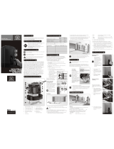
The D2 Turbo domestic sliding gate operator has been designed
solely to open and close domestic sliding gates. It must not be
installed or used to automate the entrances of townhouse complexes,
housing estates, industrial sites, etc.
It is a 12V DC battery operated unit with the following limitations:
Gate mass maximum: 250kg
Starting pull force: < 18kgf
Rated running force: < 9kgf
Maximum speed: 24 metres/minute
Maximum gate length: 10 metres
Design life: Ten years at ten cycles per day
Please do not proceed with the installation until you
have read and fully understand the Safety instructions
included in your product packaging. The Safety
instructions are also available on www.centsys.co.za,
and may also be obtained by contacting Centurion
Systems on +27 860 236 887 (SA only).
4. General description
5. Technical specifications
This icon denotes variations and other aspects that should be
considered during installation.
This icon indicates tips and other information that could be
useful during the installation.
This icon indicates a warning, caution or attention!
Please take special note of critical aspects that MUST
be adhered to in order to prevent injury.
2. Important safety instructions
8A.1. Insert the camlock key
and rotate it 90°
clockwise. This will allow
for the removal of the
cover, as well as for the
rotation of the release
thumbwheel.
8A.2. The motor pinion can be
put into ‘manual mode’
(unlocked) by rotating
the thumbwheel counter-
clockwise through
approximately 90°.
Using the camlock, it is possible to lock the operator cover in
place with the release thumbwheel in either the ‘locked’ or
‘unlocked’ position
When locked, the release thumbwheel cannot be moved from
‘locked’ to ‘unlocked’ or vice versa
Mount the operator
8A. Selecting manual mode
Ensure that all the standard considerations for a
quality gate installation are adhered to as specified in
CENTURION’s comprehensive installation manuals. If
you are unfamiliar with these, then you may find them
on www.centsys.co.za. However, as a minimum please
ensure that:
&
Unobstructed access in and out of the premises. The operator
must not protrude into the driveway.
&
Endstops are mandatory and must be capable of stopping the
gate at rated speed
&
Guide-rollers and anti-lift brackets are correctly fitted
&
The specified gate mass, starting- and rated-pull-force
limitations are not exceeded
&
All relevant safety instructions are adhered to
8. D2 Turbo operator installation
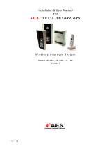
7. Cabling requirements
Legend
1. 220V AC mains cable via double pole mains isolator switch
2
(3 core LNE 1.5mm SWA)
Optional wiring (all cable is multi-stranded):
2
2. Intercom cable from motor to dwelling (n1 + 6 core 0.5mm )
2
3. Intercom cable from motor to entry panel (n2 0.5mm )
2
4. Safe CLS: Recommended infrared safety beams (3 core 0.5mm )
2
5. TRG: Access control device (3 core 0.5mm )
6. PED: Optional pedestrian keyswitch (a)
2
OR keypad (b) (3 core 0.5mm )
2
7. TRG: Optional external radio receiver (3 core 0.5mm )
8. LIGHT: Optional pillar lights (3 core LNE SWA, size according to
power requirements)
n1 = number of cores required by intercom
n2 = number of cores required by intercom
Possibly increase cable thickness if pillar lights are installed
Type of cable must adhere to municipal bylaws but typically SWA
(steel wire armoured) cable is recommended. The armouring
provides excellent screening, which gives better protection
against lightning – earth one end of the screening)
Allows for all features such as pedestrian opening, status LED,
etc., to be operated from the intercom handset inside the
dwelling. Number of cores and type of cable could vary depending
on brand of access control system being used
For optimum range, an external receiver can be mounted on the
wall
1
2
44
6
5
7
8
8
3
Centurion Logo
Turbo
D2
TM
2
4
3
5
7
8
9
6
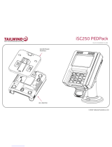
Which bit is what?
1. Motor fuse
2. Motor enclosure unit
3. Camlock cover
4. Release thumbwheel
5. Foundation plate
6. D2 Turbo controller
6. D2 Turbo identification
11
10
1
7. 12V 7.2Ah or 5Ah battery
8. Battery strap
9. Pulley guard
10. Gate mounted origin marker
11. Origin marker bracket
Centurion Logo
E&OE. Centurion Systems (Pty) Ltd. reserves the right
to change any product without prior notice.
1195.D.01.0001_2 Pocket installation guide_27Jan2011
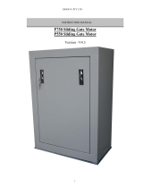
B1: Below pinion - RAZ rack
5 (Recommended to
allow for adjustment)
148 - 158
Foundation
plate
Raised
foundation
B2: Below pinion - Nylon rack
5 (Recommended to
allow for adjustment)
Foundation
plate
Raised
foundation
148 - 158
A2: Above pinion - Nylon rack
Foundation
plate
Flat bar welded
to foundation
plate and rail
5 (Recommended to
allow for adjustment)
77
130*
148 - 158
* Includes 3mm clearance required
between rack and pinion
A1: Above pinion - RAZ rack
Foundation
plate
Flat bar welded
to foundation
plate and rail
148 - 158
77
160*
5 (Recommended to
allow for adjustment)
* Includes 3mm clearance required
between rack and pinion
8B.4. Fit RAZ/Nylon angle rack as recommended by CENTURION.
Use height-adjustment nuts to obtain correct rack and pinion
mesh. Rack can be mounted above or below the pinion to suit
site conditions. Refer to illustration A1, A2, B1 and B2.
8B. Locate entry points for conduits/cables
8B.1. Cable entry is allowed for
on the far LHS corner of
the gearbox.
8B.2. Fit the mounting studs to
the foundation plate and
secure in place with the
stud locknuts.
Cable
entry points
8B.3. Position the foundation
plate to allow for the
pinion to be unmeshed
from the rack when the
gearbox has to be
removed.
Leave clearance under the
gearbox to allow for the
gearbox to be lowered if
the rack and pinion mesh
is too tight.
Check that
the rack is
just resting
on the
pinion
Level
this end
and fix
Level this end of
the rack, and fix
3mm
LOWER
3mm
tooth
gap
Foundation
plate
Mounting
studs
Stud
locknut
(M10
half-height
nut)
A gap of 3mm between
the rack and the pinion
must be maintained.
The pinion guard is
easily removed and
rotated allowing the rack
to be fitted above or
below the pinion.
8B.5. Use the orange height-
adjustment nuts
provided to level the
gearbox.
8B.6. Tighten the hold-down
nuts when the gearbox is
in the correct position.
Theft-resistant
nut and Discus
padlock are
available from
CENTURION for
sites requiring
additional
security.
Stud
locknut (M10 half-height nut)
Orange
height-
adjustment
nuts
Washer
Hold-
down
nuts
(M10
nuts)
Theft-
resistant
nut
Discus
padlock
Take care with the
orientation of the arrow
on the origin marker. This
arrow must face the
operator.
8B.7. Mount gate origin
marker to rack as per
illustration C, D and E,
with the gate in the
closed position.
8B.8. Battery is fitted between
the motor enclosure
unit and the D2 Turbo
controller.
8B.9. Unclip the orange clips
holding the controller
onto the motor enclosure
unit.
8B.10. Fit the 7.2Ah/5Ah
battery and clip the
orange clips down to
secure the battery in
place.
Unclip
orange
battery
clip
Clip
orange
battery
clip to
secure
Fit the
7Ah/5Ah
battery
Origin sensor
inside motor
enclosure
Origin
marker
TurboTurbo
10-17mm
Gate
Rack
E: Plan view
Greater than 500mm
Gate in
closed
position
TurboTurbo
D: Plan view
Origin
marker
Greater than 500mm
C: Isometric view