Centurion D2 Turbo Installation guide
- Category
- Garden tools
- Type
- Installation guide
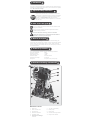
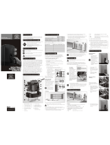
Centurion D2 Turbo is a cost-effective domestic sliding gate operator for gates weighing up to 250kg. It features a low-voltage AC or DC input, eliminating the need for high-voltage cable runs and reducing the risk of electric shock. The unit is powered by a 12V DC battery and provides a starting pull force of less than 18kgf and a rated running force of less than 9kgf. It can move gates at a maximum speed of 24 meters per minute and supports a maximum gate length of 10 meters. The D2 Turbo also includes a built-in charger, allowing for easy charging of the battery.
Centurion D2 Turbo is a cost-effective domestic sliding gate operator for gates weighing up to 250kg. It features a low-voltage AC or DC input, eliminating the need for high-voltage cable runs and reducing the risk of electric shock. The unit is powered by a 12V DC battery and provides a starting pull force of less than 18kgf and a rated running force of less than 9kgf. It can move gates at a maximum speed of 24 meters per minute and supports a maximum gate length of 10 meters. The D2 Turbo also includes a built-in charger, allowing for easy charging of the battery.


-
 1
1
-
 2
2
-
 3
3
-
 4
4
-
 5
5
-
 6
6
-
 7
7
-
 8
8
-
 9
9


Centurion D2 Turbo Installation guide
- Category
- Garden tools
- Type
- Installation guide
Centurion D2 Turbo is a cost-effective domestic sliding gate operator for gates weighing up to 250kg. It features a low-voltage AC or DC input, eliminating the need for high-voltage cable runs and reducing the risk of electric shock. The unit is powered by a 12V DC battery and provides a starting pull force of less than 18kgf and a rated running force of less than 9kgf. It can move gates at a maximum speed of 24 meters per minute and supports a maximum gate length of 10 meters. The D2 Turbo also includes a built-in charger, allowing for easy charging of the battery.
Ask a question and I''ll find the answer in the document
Finding information in a document is now easier with AI
Related papers
-
Centurion D2 Turbo Pocket Installation Manual
-
-
-
-
Centurion D5-EVO REPAIR User manual
-
-
-
Centurion A5 User manual
-
-
Other documents
-
 Centsys D10 Turbo Installation guide
-
Centsys D5-EVO Installation guide
-
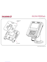 Tailwind iSC480 PEDPack Quick Installation Manual
-
Centsys 24 – 12 Volt DC-DC Regulator User guide
-
Centsys D10 SMART User guide
-
Vector V500 Installation guide
-
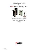 AES 603 FBK Installation & User Manual
-
Centsys D10 Installation guide
-
Centsys 1059.D.01.0001 User guide
-
 AES HBK User manual


