Page is loading ...

Certified to comply with ANSI A112.18.1
MIRROR/MEDICINE CABINET
6771
REQUIRED WALL OPENING
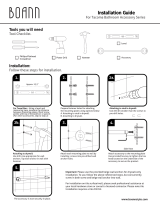
Ideally the MIRROR/MEDICINE CABINET can be installed between two wall studs on 16" centers. 2x4 reinforcement on either side are
recommended. The required opening in the wall is 14-3/8" in width by 22" from top to bottom. If wall studs are not in desired location
framing the rough opening will be required. See Illustrations below for rough opening and suggested framing.
Before installing the medicine cabinet with mirror the dry wall and any finished wall should be completed.
Determine the height and location and draw center lines to layout the wall opening.
Regular Screwdriver
Recommended Tools
LevelTape
Drill
10'
Tape Measure
Thank you for selecting American-Standard...the benchmark
of fine quality for over 100 years.
To ensure that your installation proceeds smoothly--please
read these instructions carefully before you begin.
Installation
Instructions
by
COLLECTION
™
“”
THE
14-3/8"
16"
2"
29"
16"
2x4 WALL STUD
16" ON CENTER
2x4 WALL STUDS
16" ON CENTER
SUGGESTED FRAMING
FOR ROUGH OPENING
DRY WALL AND
FINISHED WALL
INTERIOR DEPTH
4-1/8" MINIMUM
4" CABINET
DEPTH
2x4 SIDE
REINFORCEMENT
2x4 SIDE
REINFORCEMENT
2x4 TOP
SUPPORT
1/2" DRY WALL
FINISHED WALL
14-3/8"
ROUGH OPENING
OUTSIDE DIMENSIONS OF CABINET
ARE 14" X 21-3/4"
22"
A
"A - A"
A
2x4 BOTTOM
SUPPORT
Caution; Before cutting into any existing wall check that there is no interference with piping or electrical wiring.

INSTALL MIRROR/MEDICINE CABINET
Install MIRROR/MEDICINE CABINET into finished opening in wall. Check for level and that cabinet frame fits
flush against finished wall. Shim as required to make level. (Figure A)
Drill two 1/8" dia. pilot holes into top and bottom of cabinet. Secure cabinet to framing with wood screws. (Figure B)
INSTALL MOUNTING PLATES
To use TEMPLATES (A & B),
to locate the center of each MOUNTING PLATE (1), cut the template out cutting on the dotted lines.
Starting at lower left corner of cabinet frame, locate the template as illustrated. Tape into place and mark the three centers of the
MOUNTING PLATE (1). Use TEMPLATE (A) for corners 1 & 3 and TEMPLATE (B) for corners 2 & 4 marking the MOUNTING PLATE (1)
locations and mounting holes. Check with a level that the center to center measurements are level.
To use DIMENSIONS,
to locate the center of each MOUNTING PLATE (1) start at the lower left corner of cabinet frame. Measure as
indicated to locate the center of each MOUNTING PLATE (1). Mark the centers for the left side MOUNTING PLATE (1) and use the same
measurements to locate the centers of the right side. Check with a level that the center to center measurements are level.
For best installation results it is recommended to secure MOUNTING PLATES (1) to reinforcements studs. No Anchors are needed. Drill
small pilot holes for SCREWS (3).
For installations on drywall without reinforcement studs,
use DRYWALL ANCHORS (2) and SCREWS (3) for securing
MOUNTING PLATE (1) to wall. Place #2 Phillips screwdriver or cordless screwdriver into recess of anchor. Press into drywall while turning
the anchor clockwise until it is seated flush with the wall. Place MOUNTING PLATE (1) over DRYWALL ANCHOR (2) and insert SCREWS (3)
with #2 Phillips screwdriver. See FIGURE B below. Secure MOUNTING PLATE (1) to wall with SCREWS (3).
NOTE; For best installation results use:
• No Anchors, Screws (3) directly secured to
reinforcement studs
• TILE ANCHORS (4) for tile or plaster walls
• DRYWALL ANCHORS (2) for dry wall
1
2
FINISHED
WALL
2
4
3
CENTER LINE
1
PILOT HOLES
Figure A Figure B
Figure B
For installations on tiled walls without reinforcement studs,
If TILE ANCHORS (4) and SCREWS (3) are used for securing MOUNTING
PLATE (5), then drill two 1/4" diameter holes a minimum of 1-1/4" deep. Insert the two TILE ANCHORS (4) flush with face of the
finished wall. Secure MOUNTING PLATE (1) to wall with SCREWS (3).
Note: Cabinet can be installed either right hand or left hand by rotating cabinet180 degrees.
Note: Refer to Figure A for use of
TEMPLATES (A & B)
or
DIMENSIONS
to locate the four MOUNTING PLATES (1).
A
LOWER LEFT
CORNER
OF CABINET
1
1-15/16"
19-3/8"
25-1/2"
LEVEL
1-15/16"
1-3/32"
1-3/32"
Figure A
1
2
4
3

INSTALL HINGES AND SIDE MIRRORS
INSTALL GLASS SHELF
Figure A: Medicine cabinet and side mounting plates installed.
Figure B: Install ESCUTCHEON (1a) and HINGE (2a) onto bottom MOUNTING
PLATE (3a). Secure with MOUNTING SCREW (4). Do not fully tighten at this time.
Figure C: Insert HINGE (2b) into top hinge hole of MIRROR (5). Place
ESCUTCHEON (1b) onto upper MOUNTING PLATE (3b). Tape in place if necessary.
Figure D: Hold MIRROR (5) with HINGE (2b) and install MIRROR (5) onto bottom
HINGE (2a). Install upper HINGE (2b) into ESCUTCHEON (1b).
Figure E: Secure upper hinge assembly with MOUNTING SCREW (4). The gap
between the cabinet mirror and side mirror should be equal at the top and
bottom. Align if necessary. Tighten both top and bottom MOUNTING SCREWS (4)
to secure installation. Press in INDEX BUTTONS (6).
Repeat the above steps to install the opposite end mirror.
1a
3a
3b
1b 1b
1
2
2a
2b
2b
2a
5
4
Figure B Figure C Figure D Figure E
Figure A
5
6
6
4
Determine the desired location of the two GLASS SHELF UNITS (1).
Insert four SHELF PINS (2) two on each side into the side holes.
Rest GLASS SHELF (1) onto SHELF PINS (2).

1-15/16"
OUTLINE OF
MOUNTING PLATE
1-15/16"
TEMPLATE FOR
CORNERS 1 AND 3
TEMPLATE FOR
CORNERS 2 AND 4
1
2
4
3
MARK MOUNTING
LOCATION
TEMPLATE
1-3/32"
1-3/32"
6771
MODEL NUMBER
by
COLLECTION
™
“”
THE
6771
MODEL NUMBER
by
COLLECTION
™
“”
THE
1
2
4
3
OUTLINE OF
MOUNTING PLATE
MARK MOUNTING
LOCATION
C/L
Cabinet
Cabinet
C/L
C/L
C/L
TEMPLATE
/
