Page is loading ...

Installation Instructions
AdEdge Residential Drinking Water System
OPERATION MANUAL
AdEdge Technologies, Inc.
5152 Belle Wood Court, Suite A
Buford, GA 30518

1
CONTENTS
Description
INSTALLATION INSTRUCTIONS ...................... 2
COMPONENTS ................................................... 2
Cartridges .................................................... 2
Filter housings ............................................ 2
Water Meter ................................................. 2
Feed water saddle valve ............................. 2
TOOLS ................................................................ 2
SYSTEM LOCATION .......................................... 2
Faucet .......................................................... 2
Feed water connection ............................... 2
Site reparation ............................................. 2
Description
INSTALLATION STEPS ..................................... 2
1. Faucet installation .................................. 2
2. Mounting the faucet ............................... 4
3. Feed water valve and tube installation 4
4. Initial tubing connections ...................... 4
5. Unit installation ...................................... 4
6. Final tubing connection ......................... 4
ICEMAKER HOOK UP........................................ 5
SYSTEM START-UP .......................................... 5
MAINTENANCE ................................................. 5
JOHN GUEST® .................................................. 5
MODEL DWS 2 ................................................... 6

2
Installation Instructions
Residential Drinking Water Models
DWS-2S-2710-01
Your Drinking Water System has been tested to
ensure it will operate correctly. The following
periodic maintenance is recommended so your
system will provide years of trouble-free service:
Replacement parts
Cartridge #1 Cartridge #2
SED001 AD2710S
5 Micron Arsenic
Components
The following components make up your Drinking
Water System.
#1 cartridge (sediment) removes 5 micron particles
such as sand, silt, rust and scale.
#2 cartridge reduces arsenic in the feed water.
Filter housings holds the cartridges. A bracket is
provided so they may be mounted, typically below
the sink.
Water Meter counts gallons filtered and
automatically shuts the system off when capacity
has been reached.
The dedicated faucet is used to dispense filtered
water when needed.
Feed water saddle valve is connected to the cold
water line to supply water to the system.
Tubing supplies feed and filtered water.
Fittings are used for necessary hose connections.
Tools
The following tools may be necessary, depending
on each particular installation:
• 3/8” variable speed electric drill; 1/8” &1/2” bits
• 1-1/4” porcelain hole cutter (if hole for second
faucet is not provided).
• Center punch and hammer
• 1-1/4” wood bit
• Concrete drill bits
• Phillips head and flat blade screwdrivers
• Adjustable wrench
• Crescent wrench
• Teflon tape
• Plastic tube cutter
System location
Your drinking water system may be installed under
a sink, in a basement or other location, depending
on available space. Do not install unit where
temperatures fall below freezing; otherwise,
damage will result. Connection to an icemaker
should also be considered for optimum
performance.
Guidelines for component placement are as follows:
Faucet should be placed near the sink where
drinking / cooking water is normally required. A 2”
flat surface is required to mount the faucet if an
existing hole for a second faucet is not available.
The thickness of the mounting surface should not
exceed 1-1/4”.
Feed water connection is accomplished with a
self-piercing feed water saddle valve. Locate this
assembly as close to the system as possible.
Connect to a potable, cold water supply line only.
Note: Plumbing codes may require the use of air
gaps. Please check with your local municipality.
Site reparation
Installing dealers may want to speak with
customers in advance and ask them to clean under
the sink to save time. If a basement installation is
advisable, check area to determine if extra fittings
or hosing are required. Upon arrival, it is a good
idea to check the condition of all plumbing for
potential leaks and advise customer so there will be
no misunderstandings in the event leaks occur.
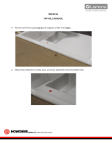
Unit preparation
Open shipping carton, remove components and
check that all parts are present.
Installation steps
All plumbing must be completed in accordance with
state and local plumbing codes. Some
municipalities may require installation by a licensed
plumber. Check local authority prior to installation.
1. Faucet installation
If the sink has a sprayer it may be disconnected for
faucet installation. (Installing dealers should
discuss this with customers.) A pipe cap or plug will
be necessary to seal the sprayer connection.

3
To make the faucet mounting hole (if sprayer or
second hole is used), check below to make sure the
drill does not interfere with anything below.
The faucet should be positioned so it empties into
the sink and the spout swivels freely for
convenience. If sink has a hole that can
accommodate the faucet, no drilling is required.
Proceed with mounting the faucet.
Porcelain, Enamel, Ceramic on Metal or Cast Iron:
Precautions must be taken to penetrate the
porcelain through to the metal base to prevent it
from chipping or scratching the surface. There are
several methods that allow ceramic sinks to be
drilled safely and easily.
Method 1:
Tools required:
• Variable speed drill
• Relton porcelain cutter tool set
(7/8" or alternative size, 9/16")
• Plumber's putty
Procedures:
1. Mark the center for the 7/8” hole.
2. Form shallow putty around hole area and fill
with enough water to lubricate carbide drill bit.
3. Carefully drill pilot hole through all layers. (Use
light pressure and slow speed.)
4. Insert pilot tip of spring-loaded porcelain cutter
into pilot hole.
5. Drill porcelain / enamel using spring loaded
porcelain cutter, making certain a complete ring
has been cut through the porcelain / enamel to
the metal base.
6. Cut away the inner porcelain / enamel disc
down to the base metal. Make certain the
cutter does not touch outer rim of the cut
porcelain / enamel. Continue until the sink has
been completely penetrated.
Note: Always use sharp cutter to eliminate chips.
Method 2:
Tools required:
• Masking Tape
• Variable speed drill
• 1/4” and 7/16” carbide drill bit
Procedures:
1. Locate faucet placement and tape off the area
with masking tape.
2. Using a drill at slow speeds, drill a pilot hole
through the porcelain using a 1/4” carbide
tipped drill. Note: The bits dull in a very short
period of time when used for drilling porcelain
and should be replaced or sharpened
frequently.
3. Cut through the porcelain and base materials
using a 7/16” carbide tipped hole saw at very
slow speeds.
Stainless steel sinks:
Center punch a small indent at the desired faucet
location. (2” flat surface is required, not exceeding
1-1/4” in thickness.) Drill the required pilot hole for
the chassis punch and tighten nut to cut the desired
hole size. Clean up sharp edges.
Recommended tools:
• Center punch
• Variable speed drill
• High speed drill bits
• Greenlee chassis punch
• Protective gloves & eye protectors

4
Procedures:
1. Center punch small indent for hole.
2. Drill the required pilot hole.
3. Set-up the chassis punch per instructions and
tighten nut to cut the desired hole size.
4. Clean up sharp edges with file.
2. Mounting the faucet
Disassemble hardware from the threaded nipple,
except for chrome base plates and rubber washers.
(Rubber washers may be replaced with bead of
plumber's putty for neater appearance.)
Feed the threaded nipple through sink or counter
mounting hole and orient the faucet. From below
sink or counter, assemble the white spacer flat
washer, star washer and hex nut on threaded nipple
and tighten by hand. After checking faucet
orientation, tighten with a wrench until secure.
Faucet installation
3. Feed water valve and tubing installation
The saddle tapping valve which is supplied is
designed for use with 3/8" to 1/2" OD soft copper
supply tubing (plain or chromed) and rigid metal
pipe. Do not use with flexible ribbed supply tubing,
which is too thin and requires special hardware.
Self-taping feed water saddle valve installation
Installation procedures using soft copper tubing:
1. Turn off cold water valve from under sink or
main water line valve for whole house.
2. Before installing saddle tapping valve, make
sure piercing lance does not protrude beyond
rubber gasket.
3. Assemble saddle valve on copper tubing.
4. Turn handle clockwise to pierce soft copper
tube until valve is firmly seated. (Valve is
closed in this position.)
5. Turn on water supply to pressure cold water
line.
6. Snug nut/seal with wrench around valve stem.
7. Connect tubing to feed water valve using brass
compression nut, insert and plastic sleeve.
Saddle valve installations with metal pipe:
1. Turn off cold water supply.
2. Drill 3/16" hole at desired location.
3. At this point, make sure piercing lance does not
protrude beyond rubber gasket.
4. Assemble saddle on to pipe, aligning with hole.
5. Turn saddle valve handle clockwise to close
valve.
6. Tighten nut/seal around valve stem with
wrench.
7. Connect tubing to feed water valve using brass
compression nut, insert and plastic sleeve.
8. Turn on cold water supply.
9. To open valve, turn handle counterclockwise
and check for leaks.
4. Initial tubing connections
For convenience on under counter installations it
may be advisable to complete under counter hose
connections at this time.
5. Unit installation
To mount the drinking water unit, elevate it at least
2" off the floor, level it and mark the location of
mounting holes needed. Drill holes for mounting
screws and install screws, allowing the mounting
bracket slots to slip over them.
Note: If the cabinet sidewalls are not solid, unit
may sit on the floor with screws to keep it against
the cabinet in a vertical position.
6. Final tubing connections
With all components in place, complete final tubing
connections using these guidelines:

5
☺ Tubing should follow contour of the cabinets.
☺ Cut tubing to desired length using square cuts
and proper cutting devise.
☺ Make no sharp bends.
☺ Keep tubing from the unit to the faucet as short
as practical for good flow.
Under sink installations following installation
diagram and the following procedures:
1. Connect tubing from faucet to meter.
2. Connect tubing from supply valve to unit.
Icemaker hookup (optional)
The drinking water device can be connected to any
standard refrigerator icemaker or icemaker / water
dispenser. (Do not connect to a commercial type
bar icemaker.)
To complete this operation, connect a tee with shut-
off valve into the faucet tubing and route tubing to
the refrigerator. (Hooking up to an existing copper
line is not recommended unless it is new
installation.) Shut off icemaker by lifting lever prior
to turning off the existing tap water supply line to
the refrigerator.
System start-up
Prior to start-up:
1. Check all connections be sure they are secure.
2. Turn on feed water valve and check for leaks.
(Turn off and correct leaks if leaks occur.)
3. Close faucet and wait five minutes to see if
leaks result.
4. If no leaks are present, turn metering valve
clockwise and set to 800 if AD2710C cartridge
is installed. Otherwise, set to gallons
recommended for your cartridge.
5. Open faucet and run water for approximately
ten minutes to condition filter cartridges. Initial
water may be slightly discolored or contain a
few small particles of filter media. These
particles are harmless and non-toxic. This is
normal during filter conditioning, and will
subside prior to the end of the 10 minute period.
Maintenance
Your drinking water system contains cartridges
which must be replaced periodically for proper
operation. (Please see page 2 for cartridge
information)
Note: Change-out procedures may be amended,
depending on source water conditions.
To change filter cartridges follow these procedures:
1. Close feed water valve by turning it clockwise.
2. Open faucet to release pressure.
3. Loosen and remove filter housings using
wrench provided and discard cartridges.
4. Wash the inside of the housings using mild
detergent and soft cloth. Thoroughly rinse all
soap before reassembly.
5. Replace filter cartridges.
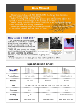
John Guest® brand fittings
Model DWS-2S-2710-01 utilizes John Guest®
brand fittings. These user-friendly fittings provide
superior performance and virtually eliminate the
potential for leaks. Proper use of these push-in
fittings is shown below. Along with these fittings, all
tubing selected must be of high quality and must be
cut with a plastic tube cutter or sharp razor with a
clean, square cut.
Should a leak occur at a fitting, the cause is
generally defective tubing. To fix a leak, relieve
pressure, release tubing, cut off at least 1/4" from
the end (square cut), reattach the tubing and
confirm the connection is leak free. Each time a
new connection is made, it is advisable to cut off
1/4" from the end of the tubing using these fittings.

2
Conventional fittings
If John Guest fittings are not used, it is essential
to install inserts at the ends of all tube
connections when conventional fittings are used.
Model DWS-2S-2710-01
This model includes a sediment cartridge, arsenic cartridge (AD2710S), two filter housings, faucet, feed water
saddle valve, tubing, fittings and a water meter which will count gallons and automatically shut off the system
once 1000 gallons has been filtered. This special component indicates when cartridges should be replaced, and
will help assure fresh, filtered water will be provided at all times. On this model the fitting located on the meter is
the outlet of the system. Connect tubing from this fitting to the faucet.
/