Crystal Quest CQE-RO-00108 Operating instructions

Category
Sanitary ware
Type
Operating instructions
1
Crystal Quest
®
THUNDER
®
Series
Reverse Osmosis Undersink Water Filter System
INSTALLATION AND OPERATION GUIDE
COMPONENT S
Copyright 2017
Crystal Quest
®
All rights reserved
MADE IN THE USA
2
IMPORTANT INFORMATION
TOOLS & MATERIALS
INSTALLATION STEPS
MODELS
i
Inspect the carton and unit for evidence of rough handling and concealed damages. If contents appear damaged, report
damage to the carrier. Notify Shipper immediately.
Remove components from shipping carton. Check that all installation parts are present, which includes the unit, storage tank,
faucet, installation hardware, and tubing.
Check that the air supply in the tank is approximately 7 psi. Adjust if necessary.
Readtheinstructionscarefullyandlearnthespecicdetailsregardinginstallationanduse.Failuretofollowthemcouldcause
serious property damage. Crystal Quest
®
accepts no liability for property damage.
The system should be installed to meet local, state, and federal plumbing codes, and health department rules and
regulations. The guidelines must be followed as the Reverse Osmosis system is installed.
Allequipmentshouldbeplumbedintothewatersystembyaqualied,licensedplumber.
Check with your local public works department for plumbing codes.
Use the system on a potable (safe to drink) COLD water supply only.
Note: It is recommended that a Under Sink Detector Smart Valve (CQE-PT-03060) be placed directly upstream of your
householdltertopreventwaterdamage.
Safety glasses
3/8” variable speed electric drill, 1/8” and ½” bits
1-1/4” porcelain hole cutter (if hole for second faucet is not provided)
Extensioncord,droplightorashlight
Plastic anchors and screws
Plastic tube cutter
Air pressure gauge (low pressure)
• Pliers
Step1.........................................InstallFaucetpg.3
Step 2 ......................................... Install Saddle Valve pg. 4
Step 3 ......................................... Install Drain Connection pg. 4
Step 4 ......................................... Install Tank pg. 5
1,000 C (CQE-RO-00101)
1,000 CP (CQE-RO-00105)
1,000 M (CQE-RO-00109)
1,000 MP (CQE-RO-00113)
Phillipsheadandatheadscrewdrivers
1-1/4” wood bit
Household bleach (liquid)
Adjustable wrench
Crescent wrench
Thread seal tape
Air pump (hand)
OPERATINGSPECIFICATIONS:
Pressure Range: 30-60 psi (2.1-4.1 bar)
TemperatureRange: 40-85°F(4.4-29.4°C)
OptimumServiceFlow: 0.30gpmat60psi(1.1lpmat4.1bar)
ELECTRICAL REQUIREMENTS:
110V 50Hz (North and South America)
220-240V 60Hz (Other Continents)
2,000 C (CQE-RO-00102)
2,000 CP (CQE-RO-00106)
2,000 M (CQE-RO-00110)
2,000 MP (CQE-RO-00114)
3,000 C (CQE-RO-00103)
3,000 CP (CQE-RO-00107)
3,000 M (CQE-RO-00111)
3,000 MP (CQE-RO-00115)
4,000 C (CQE-RO-00104)
4,000 CP (CQE-RO-00108)
4,000 M (CQE-RO-00112)
4,000 MP (CQE-RO-00116)
3
IMPORTANT INFORMATION
The faucet to be used for your reverse osmosis system (RO) should be placed near the sink where drinking/cooking water is
normally required. A 2” at surface is required to mount the faucet if an existing hole for a second faucet is not available. The
mounting thickness should not exceed 1-1/4”. If the sink has a sprayer, it may be disconnected for faucet installation. A pipe
cap or plug will be necessary to seal the sprayer connection. If making the faucet mounting hole (if sprayer of second hole is not
used), check to make sure the drill does not interfere with anything below. Center punch a small indent at the desired faucet
location(2”atsurfaceisrequired,notexceeding1-1/4”inthickness).Drilltherequiredpilotholeofthechassispunchand
tighten nut to cut the desired hole size. Clean up sharp edges. The faucet should be positioned so it empties into the sink and
the spout swivels freely for convenience. If sink has a hole that can accommodate the RO faucet, no drilling is required. Proceed
with mounting the faucet.
MOUNTINGTHEFAUCET:
Disassemble hardware from the threaded nipple, except for chrome base plates and rubber washers. (Rubber washers may be
replacedwithabeadorplumber’sputtyforneaterappearance.)Feedthethreadednipplethroughsinkorcountermounting
holeandpositionthefaucet.Frombelowsinkofcounter,assemblethewhitespacer,atwasher,andhexnutonthreaded
nipple and tighten by hand (open end up; open side toward air gap). After checking faucet orientation, tighten with a wrench
untilsecure(Fig1).
INSTALL FOR STAINLESS STEEL SINKS
Recommended Tools:
Center punch
Variable speed drill
High speed drill bits
Chassis punch 7/8” (9/16” for non air gap faucets)
Protective gloves and eye protectors
Procedures:
1. Center punch small indent for hole.
2. Drill the required pilot hole.
3. Set-up the chassis punch per instructions and tighten nut
to cut the desired hole size.
4. Cleanupsharpedgeswithle.
Precautions must be taken to penetrate the porcelain through
to the metal base and prevent it from chipping or scratching.
Recommended Tools:
Variable speed drill
Plumber’s putty
Porcelain cutter tool set (7/8” or alternative size, 9/16”)
Procedures:
1. Mark the center for the 7/8” hole.
2. Formshallowputtyaroundholeareaandllwith
enough water to lubricate carbide drill bit.
3. Carefully drill pilot hole through all layers (use light
pressure and slow speed).
4. Insert pilot tip of spring-loaded porcelain cutter into
pilot hole.
5. Drill porcelain/enamel disc down to the base metal.
Make certain the cutter does not touch outer rim of the
cut porcelain/enamel. Continue with this bit to cut
through metal until sink has been completely penetrated.
NOTE: Always use sharpened porcelain cutter to eliminate
chips and cracks.
INSTALL FOR PORCELAIN, ENAMEL,
CERAMIC ON METAL OR CAST IRON
(Fig.1)
Faucet
Rubber washer
Chrome base plate
Rubber washer
Sink/countertop
Plastic washer
Star washer
Hex nut
Compression nut
Plastic ferrule
Plastic tubing insert
1/4” white tubing
4
STEP 2: INSTALLING VALVE OPTIONS
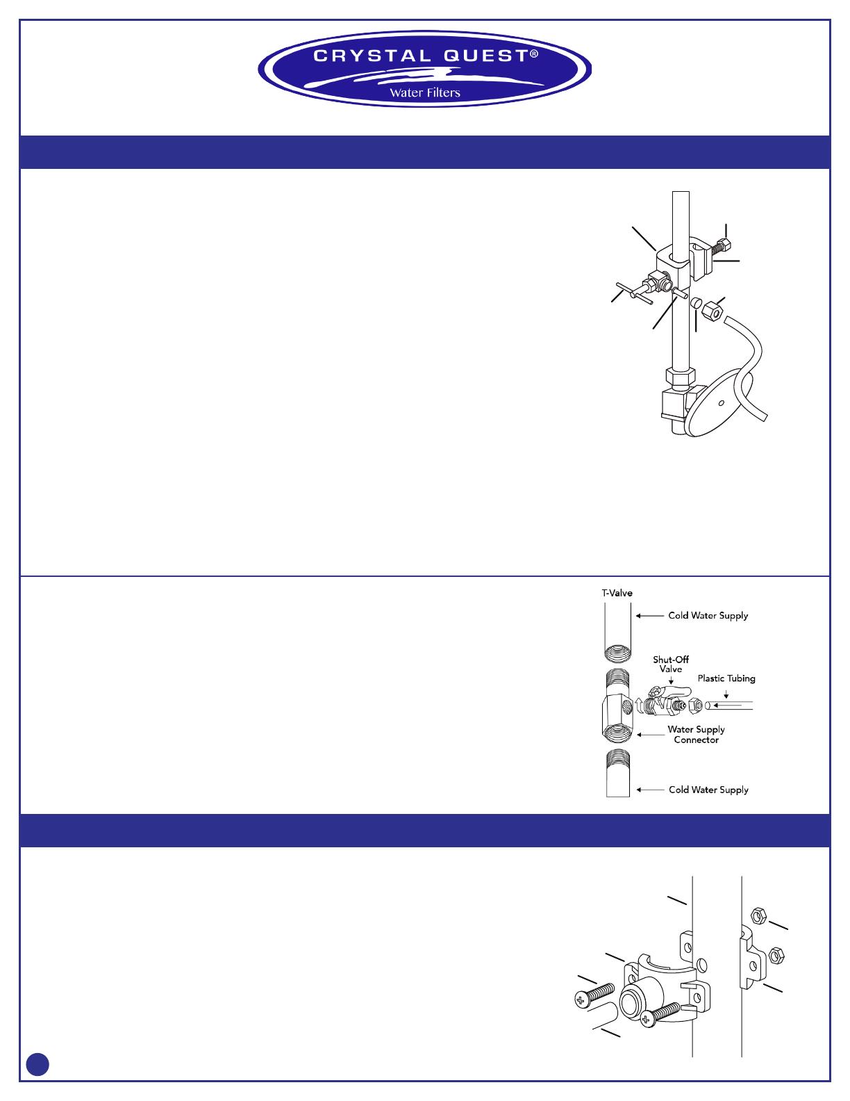
STEP 3: INSTALL THE DRAIN CONNECTION
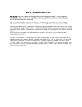
SADDLE VALVE INSTALLATION
Choose the Valve Location:
Choose a location for the valve that is easily accessible. It is best to connect into the side of a vertical water
pipe. When it is necessary to connect into a horizontal water pipe, make the connection to the top or side,
rather than at the bottom, to avoid drawing off any sediment from the water pipe.
Disconnect the cold-water supply line. Attach and tighten the saddle valve connector assembly being careful
nottopinchorcrimpanytubingorwatersupplylinewhiletightening.Usethreadsealtapetoensureatightt.
NOTE: The saddle valve clamps onto soft or hard tubing or pipe. It will make its own hole in copper tubing but not
inironorbrass.Forbrassorgalvanizedironpipe,drilla¼”holeinpipebeforemountingsaddlevalve.Ifpossible,
use a hand or cordless drill when drilling water pipe. If using electric drill, be sure that drill, cord, and outlet are all
properly grounded.
NOTE: Do not turn handle before installing or while installing saddle valve. To prevent damage to piercing needle,
make sure that piercing lance does not project beyond the rubber gasket.
NOTE:Leavehandleinthisposition(valveclosed)untillterinstallationiscomplete.
1. Hold backplate against tube.
2. Hold saddle valve against tubing in a position directly opposite backplate.
3. Tighten screw enough so saddle valve and backplate are held securely against tube.
4. Tightenscrewrmly.Donotcrushtube.
CONNECTSOURCEWATERFEEDTUBINGTOVALVEBODYUSINGCOMPRESSIONFITTING.
1. Slide nut and sleeve onto tubing (in that order).
2. Install insert into tubing.
3. Install tubing with insert and sleeve into valve body.
4. Thread compression nut onto valve body. Tighten.
5. Turnsaddle-tappingvalvehandleclockwiseuntilitisrmlyseatedandpiercinglanceisfullyextended.
CAUTION: When the supply line is pierced, the valve should be closed. Do not open valve until system is activated.
Turn on cold water supply. Check saddle-tapping valve installation for leaks. Allow water to run from faucet for a
few minutes to clear any debris in the line caused by installation.
NOTE:Ifowfromsinkfaucetisreduced,cleanfaucetaerator.
T-VALVE INSTALLATION
WARNING: Water supply pressure must not exceed 60 psi.
NOTE:T-Valveisdesignedforinstallationonexlinetubing.
NOTE: Always check the local plumbing codes before tapping into a water line.
1. Turn off cold water supply.
2. Assemble T-Valve by screwing and tightening the shut-off valve into the water supply connector (use thread
seal tape on threads).
3. Disconnect source water feed tubing from cold water supply.
4. Install T-Valve assembly in line with water feed tubing and water supply.
5. Removenutfromfeedendofshut-offvalveandslideoverltersupplytubing.
6. Press end of tubing over exposed nipple on shut-off valve. Ensure it is completely seated.
7. Slide nut down tubing and tighten securely to shut-off valve.
8. Slowly turn cold water supply on and check for leaks.
9. OpenT-Valveshut-offvalveslowlytosupplywatertolter
ForfurtherinstructionsonT-Valveassembly,seeT-Valveproductlabel.
IMPORTANT:Beforestartingthisprocedure,inspecttheconditionifthedrainpiping,especiallyinolderhomes
where the traps and tailpieces can be thin and frail. If in poor condition, it is wise to inform the customer that the
conditionshouldberemedied.Thedrainsaddleassemblyisdesignedtotaroundastandard1-1/2”ODdrain
pipe. The drain saddle should always be installed above (before) the trap and on the vertical or horizontal tailpiece.
Never install the drain saddle close to the outlet of a garbage disposal, or plugging of the RO drain line may occur.
1. Peel adhesive covering from the back of foam square gasket, line up with the hole in the drain saddle, and
apply. This gasket provides a leakproof seal on the drain pipe.
2. Position both halves of drain saddle at desired location on drain pipe.
3. Use screws and nuts to clamp drain saddle onto drain pipe. Do not overtighten or cross-thread, and make sure
there is equal space between saddle halves on each side.
4. Carefullydrillholethroughthettingfrontholeofdrainsaddle,beingcarefulnottodrillthroughoppositeside
of drain pipe.
5. Wrapthreadsealtapeonthreadsoftting(ifany),insertdraintubingintodrainsaddle,andtightennutifitisa
compressiontting.
Tightening
screw
Reversible
plate
Compression
nut
Insert
Valve handle
Valve body
Sleeve
(Fig.2)
Tubing
(Fig.3)
Drain Pipe
Drain Clamp
Front Plate
Drain Clamp
BackPlate
(Fig.4)
Cold water supply line
Nut
Screw
Drain Tubing
5
STEP 4: INSTALL THE STORAGE TANK
MAKE FINAL TUBING CONNECTIONS
INSTALL ICEMAKER HOOKUP (OPTIONAL)
Hand tighten tank ball shut-off valve to tank, connect tubing.
PREFILLANDSANITIZETHESTORAGETANK
Prellingthetankisalwaysrecommendedsothereispressuretocheckforleaksandseveral
gallonsofwatertoushthecarbonpost-lter.Tanksarefurnishedwithaspecialdisinfectant
andonlyrequirellingwithwaterfor15minutestobecompletelysanitized.Itisimportant
touseasanitizerwhenprellingthetanksothesolutioncansanitizethetubing,ttings,and
faucet at the time of installation and startup.
1. Insertfreeendoffeedwatertubingintothettingonthestoragetank.
2. Openfeedwatervalveandtankvalveandallowtanktoll(about3minutes).
3. Turn off feed water valve and tank valve. Remove tank from tubing and set the tank aside
(15 minutes minimum).
INSTALLTHEREVERSEOSMOSISANDSTORAGETANK
The RO is usually mounted to the right or left sink cabinet sidewall, taking into consideration
the space available and the tank location. Generally, the tank is placed in the rear of the
cabinet while the RO is positioned toward the front for cartridge accessibility. To mount the
RO,elevateatleast2”offthecabinetoorand,whilekeepinglevel,markthelocationofthe
mounting holes on cabinet sidewall. Make small pilot holes with an awl or drill, and screw in
the two mounting screws, leaving just enough protrusion to allow bracket mounting slots to
slide over them.
NOTE: If the cabinet sidewalls are not of solid construction, the unit can be set on the cabinet
oorandheldagainstthesidewallwiththemountingscrews.Thetankmaybeorientedeither
vertically or horizontally. It is generally placed to the rear of the cabinet but can be set in the
front center (between the sink basins) for ease of access, if space permits.
Withallofthecomponentsinplace,thenaltubingconnectionscanbemade.Whenrouting
tubing between components, several guidelines should be observed.
Tubing runs should generally follow the contour of the cabinet rather than interfere with
the cabinet storage area.
• Striveforneatnessandanorderlytubing“ow”usingfastenerstosecurethetubing.Cut
tubing to the desired length.
Arrange the tubing so that there are no sharp bends and leave some “play” in the tubing
for ease of servicing.
• KeepthetubingfromtheROtothetankandfaucetasshortaspracticalforgoodow.
The RO drinking water appliance can be connected to any standard refrigerator icemaker
or icemaker/water dispenser. It should never be connected to a commercial ice maker.
Hooking up an icemaker involves connecting a tee with shut-off valve into the faucet tubing
androutingtubingtotherefrigerator.Donothookuptoexistingcoppertubing.Before
turning off the existing tap water supply to a refrigerator icemaker, always shut off the
icemakerrst(usuallybyliftingtheleverarmabovethebintotheuppermostposition).
The icemaker should only be turned on again after the RO system has been drained several
times and the tank has a full supply of water
NOTE:BeforeanyserviceisperformedontheROsystem,alwaysturnofficemakervalve
andtheicemakerunit.Turnononlywhensystemisoperatingandtankisfull.Besurewater
is properly alkalined for refrigerator feed lines.
Tank ball shut-off valve
(Fig.5)
Line to Refrigerador
Ice Maker
Ouick
Connect
Merger
To Tank
Drain
Inlet
LinetoFiltered Water Outlet
Post-Filter
Membrane
Cartridges (3)
(Fig.6)
6
STARTING UP THE SYSTEM
OPERATION AND MAINTENANCE
Double check that all connections are secure.
Turn on feedwater valve and check for leaks. If any leaks are noted, turn off valve and correct before proceeding.
• Turnonstoragetankvalveandopenfaucetuntilasteadystreamofwaterows.Closefaucet.Waitatleast5minutesandcarefullycheckforleaks.
FLUSHSYSTEMOFSANITIZINGSOLUTIONANDCHECKOPERATION
Lift faucet handle and allow tank to drain completely of sanitizing solution. DO NOT USE THIS WATER. When tank is empty, the faucet will steadily drip. This is the rate
water is processed by the RO system.
With faucet in “off” position, measure the rate of the steady drip from spout. Use a graduated cylinder (in milliliters) and watch with a second hand to calculate
approximateproductingallonsperday(millilitersperminuteX0.38=gpd).Proceedtocheckrejectowratebydisconnectingtubingatdrainconnectionandmeasureas
per above. The ratio should be a minimum of 2.5 (reject) to 1 (product).
Close faucet and re-inspect system for leaks. Instruct customer to wait at least 4 hours and drain tank again. The water should be discarded, as it may contain some
sanitizing/disinfectant solution.
• Systemshouldbereadytouseassoonasthetankrells.Ifanyobjectionabletasteisnoticedaftersecondtankdraining,instructcustomertowaitanddraintankthe
following day. Only at this time should an icemaker be turned on if one is connected to the system.
Normal Operation
• ItisnormalfortheTotalDissolvedSolids(TDS)ofthewatertobehighthannormalduringtherst5gallonsofoperation.Thisisduetothesanitizingsolutionandthe
newpostlter.Afterthisrinsewaterhasdrained,theremovalrateshouldstabilizeatavaluegreaterthan75%.Waterpressureaffectstheproductionrateandquality.
• ROsystemsproducedrinkingwateratrelativelyslowrates.Itcantakeupto8hoursormoretolltheholdingtank.Normaloperationistolettheholdingtankllwith
water and then draw water as needed. When the pressure in the holding tank falls to a given pressure (as the water is being used), the automatic shut-off valve will start
waterproductionandthesystemwillrelltheholdingtank.Whentheholdingtankisfullandnowaterisbeingused,theautomaticshut-offvalvewillautomaticallyshut
off the feedwater to conserve water. The more water that is used (up to the capacity of the system), the better the RO system will function. Utilize the water for other
uses,suchasowers,pets,andrinsingglassware.Afterperiodsofnon-use,suchasaweek’svacation,emptytheholdingtankandallowthesystemtoproducefresh
water. If the system is not used for 3-4 weeks or longer, it is a good idea to re-sanitize the system and to change the carbon and sediment cartridges.
WATER LEAKS
Yoursystemhasbeentestedbeforeleavingthefactory.Intheunlikelyeventofafault,smallleakssometimesdooccurasa
result of incorrect assembly or abuse. The following tips may be helpful:
• Dependingonthepositioningofthelterandthetemperatureoftheincomingwaterandair,condensationonthe
outsideofthelterhousingmayoccur,resultinginafrostedappearanceofnewaterdropletsonthesurface.Thisdoes
not,ofcourse,meanthatthereisaleakinthesystem.Theremedyistoeitherinsulatetheareaaroundthelteror
reposition it.
Leaks can occur if cartridge is not installed properly. Cartridge must be installed according to the directional arrow on
the cartridge which indicates “This End Towards Cap”.
Always ensure that sump top is snapped into sump by being pushed in.
Always ensure that the sump ring is screwed fully onto the sump top. This is essential both for the internal seal and the
housing seal. Use thread seal tape around sump if necessary.
In the event of a leak, carefully examine its source. Water from a leak may run along the pipe work. (It may drip or collect
some distance from the actual location of the leak.)
Leaks occurring at the line saddle valve may mean that the unit has not been fully clamped onto the water line. (Adhere
to the instructions given on page 4.)
• Leaksatthequickttingsareusuallyduetothetubingnotbeingpushedfullyintothetting.Removethetubing,cut
offaninchoftubingwithasharpknifeandreinsertintothequicktting.Ensurethatthequicktcolletisinposition.
Whenttedcorrectly,thetubeshouldnotpulloutofthetting(unlessthecolletispushedinatthesametimeto
release the tubing).
• Ifthereareleaksatthecompressionttings,makesurethatthecomponentsarettedcorrectlyandthatthe
compression nuts are fully tightened.
• Ifthereisaleakfromthebodyofthefaucet,checkthatthetapoutletarmispusheddownrmly.TwoO-ringsaretting
to the faucet outlet spout; ensure they are still in position.
• Ifthereisaleakfromthewaterlterinletandoutlet,unscrewtting,wrapthreadsealtapearoundit,andscrewitback.
Leak Detector
Installation
(Fig.7)
Line to Refrigerator
Ice Maker
LinetoFiltered
Water Outlet
Quick
Connect
Solenoid
Valve
Merger
Tank
Drain
Controller
Module/
Sensor*
*Move sensor as close to
filter as possible. Upon
sensing moisture, controller
will engage the shut-off
value and sound an alarm.
Inlet
S
o
l
enoi
d
Va
lv
e
7
CHANGING CARTRIDGES
CHANGING POST FILTER & MEMBRANE
NOTE: THISROSYSTEMCONTAINSCARTRIDGESWHICHMUSTBEREPLACEDATREGULARINTERVALS.TO
MAINTAINPROPERPERFORMANCEUSEONLYFACTORYAPPROVEDCARTRIDGES.
Useadrippantocatchanywaterthatmightspillwhenthelterhousingsareremoved.
1) Close the saddle-tapping valve by turning fully clockwise and open the dispensing faucet by lifting
the handle. Allow the holding tank to empty.
2) Loosen(TURNCOUNTERCLOCKWISETOLOOSENandTURNCLOCKWISETOTIGHTEN)and
removetheappropriatelterhousing.Discardthecartridge(s)(Fig11).
Sanitizethesystemandreplacetheltercartridge(s).
NOTE: Thesystemshouldbesanitizedbeforeinstallingthepostltercartridge.
3) Wash the inside of the housing(s) using a mild detergent and a soft cloth. Do not use abrasive
cleaners or pads. Thoroughly rinse all soap from the housing before reassembly.
a. Use a good quality 5-1/4 percent liquid bleach, such as Clorox®.
b. Addonecapfulofbleach(2teaspoons/10milliliters)tothesedimentlterhousing.Installthe
sedimentprelteronly.CheckthehousingO-ringforproperpositioninitgroove.Replacesediment
lterhousingonROassembly.
c. IfyourROsystemhasacarbonprelterhousing,addonecapfulofbleach.Carefullyllthehousing
withtapwaterandtemporarilyinstallthehousing,withouttheactivatedcarbonprelterhousing.
d. Addonecapfulofbleachtothepostlterhousing.Carefullyllthehousingwithtapwaterand
temporarilyinstallthehousing,withoutthepostlter.
e. The dispensing faucet should be open. Slowly open the saddle-tapping valve on the feedwater line.
CHANGINGPOSTFILTERCARTRIDGES
1. Loosentheconnectorttingcounterclockwise(Fig8).
2. Pull the cartridge out of the main fold.
3. Wraptheconnectorttingwiththreadsealtapeandconnectittoanewcartridge(Fig9).
CHANGINGMEMBRANE
1. Loosentheconnectorttingcounterclockwise(Fig10).
2. Remove the membrane housing cap counterclockwise.
3. Removethemembranewithapincer(Fig11).
4. Insert the membrane by carefully pushing the spigot and into the socket at the far end of
thehousinguntilcompletelyseated(Fig12).
5. Wraptheconnectorttingwiththreadsealtapeandconnectittothetubing(Fig13).
f. As soon as water begins to drip out of the dispensing faucet, close the faucet.
g. Let the system stand for 15 minutes.
h. After 15 minutes, (1) close the saddle-tapping valve, (2) close the holding tank valve, and (3) open the dispensing faucet to release the pressure.
i. Removethepost-lterhousingandempty(repeatprocedureifyoursystemhasapre-lterhousing).
4) Remove any wrapping/packaging from carbon cartridges and install in housings. Check the O-ring to ensure that it is positioned properly in its groove and replace
housing(s) on RO unit.
5) Disconnect the water tubing that runs from the holding tank. Put 50 drops (1/2 teaspoon/3 milliliters) of bleach into the tubing and reconnect it.
6) Slowly open the saddle-tapping valve. When water begins dripping out of the dispensing faucet, (a) close the faucet and (b) open the holding tank valve.
7) Do not open the faucet for at least 8 hours.
8) Discardthersttwofulltanksofwaterproduces,astheywillcontainchlorine.
9) Whenthefaucetisrstopened,expectairandcarbonnes(veryneblackpowder)fromthenewcarbonlter(s)toberinsedout.Thisisnormalforthersttankof
water.
To change the UV bulb, follow instructions provided in the UV Guide.
(Fig.8)
(Fig.9)
(Fig.10)
(Fig.11)
(Fig.12)
(Fig.13)
(Fig.14)
Sump
Wrench
Sump
Turn counterclockwise
to remove
Turn clockwise
to tighten
8
ONE-YEAR LIMITED WARRANTY
CRYSTALQUEST
®
warrantsyourCRYSTALQUEST
®
THUNDER
®
Undersink Reverse Osmosis System for one year
from the date of purchase against all defects in materials and workmanship when used in compliance with the
manual.Thiswarrantydoesnotincludereplacementcartridgesunlessdefectiveuponreceipt.CRYSTALQUEST
®
disclaims all implied warranties including, without limitation, warranties of merchantability and tness for a
particular purpose. If for any reason the product proves to be defective within one year from the date of purchase,
pleasecallforassistance.Thiswarrantygivesyouspeciclegalrightsandyoumayhaveotherlegalrightswhich
varyfromstatetostate.CRYSTALQUEST
®
assumes no responsibility for incidental or consequential damages;
for damages arising out of misuse of the product, or the use of any unauthorized attachment. Some states do
not allow the exclusion or limitation of implied warranties or incidental or consequential damages; therefore, the
above limitations or exclusions may not apply to you. Should service be required during or after the warranty
periodor shouldyou haveany questionsregardinghowtouseyourCRYSTAL QUEST
®
THUNDER
®
Undersink
Reverse Osmosis System, please contact our Technical Support Department at [email protected], Monday
throughFriday,9AMto5PMEasternTime.
KEEPTHISMANUALFORFUTUREREFERENCEANDUNITMAINTENANCE
Online warranty information
http://crystalquest.com/warranty.htm
Product design is subject to change without notice.
Forfurtherassistance,contactyourCrystalQuestdealer
or visit us at www.crystalquest.com
To view the latest edition of the Mega Undersink Water Filter, visit CrystalQuest.com
Please note all drawings, pictures, colors and sizes are approximate for illustrative
purposes only and may not exactly resemble the end product.
TO ORDER REPLACEMENT CARTRIDGES
ItemNo.CQE-RC-040005-MicronCarbonBlockFilterCartridge
ItemNo.CQE-RC-040015-MicronSedimentReusablePleatedFilterCartridge
ItemNo.CQE-RC-040022-7/8”x9-3/4”SMARTPLUSFilterCartridge
ItemNo.CQE-RC-040552-7/8”x9-3/4”UFMembraneFilterCartridge
ItemNo.CQE-RC-04038WaterCooler/ReverseOsmosisGACFilterCartridge
ItemNo.CQE-RC-04040WaterCooler/ReverseOsmosisSMARTFilterCartridge
Item No. CQE-RC-04054 Natural (Alkalizer) Ionizer, Mineralizer, and Oxidation Cartridge
ItemNo.CQE-RC-040062-7/8”x9-3/4”FluorideFilterCartridge
ItemNo.CQE-RC-040492-7/8”x9-3/4”SMARTFluorideCartridge
ItemNo.CQE-RC-040072-7/8”x9-3/4”NitrateFilterCartridge
Item No. CQE-RC-04050 2-7/8” x 9-3/4” SMART Nitrate Cartridge
ItemNo.CQE-RC-040082-7/8”x9-3/4”ArsenicFilterCartridge
Item No. CQE-RC-04051 2-7/8” x 9-3/4” SMART Arsenic Cartridge
Should service be required
during or after the warranty period or
should you have any questions regarding how to use your
Commercial Water Purification System,
please contact manufacturer’s
Technical Support Department Monday through Friday,
9 AM to 5 PM Eastern Time,
or your authorized CRYSTAL QUEST dealer:
Mailing Address:
FilterWater.com
P.O. Box 968
Sou
thampton, PA 18966
USA
http://www.FilterWater.com
Tel.
+1 (800) 439-0263
Fax +1 (215) 354-0304
AUTHORIZED DISTRIBUTOR
9
  • Page 1 1
  • Page 2 2
  • Page 3 3
  • Page 4 4
  • Page 5 5
  • Page 6 6
  • Page 7 7
  • Page 8 8
  • Page 9 9

Crystal Quest CQE-RO-00108 Operating instructions

Category
Sanitary ware
Type
Operating instructions

Ask a question and I''ll find the answer in the document

Finding information in a document is now easier with AI