Page is loading ...


Installation Instructions
Residential Reverse Osmosis Drinking Water System
Your Reverse Osmosis System has been tested to
ensure it will operate correctly. The following periodic
maintenance is recommended so your system will
provide years of trouble-free service:
Replacement part Frequency
Pre- lter (sediment) Every 6 mos.
Pre- lters (activated carbon) Every 6 mos.
R/O membrane Every 2-3 years
Post lter (carbon) Every 6 mos.
Components
The following components make up your Reverse Osmosis
Drinking Water System:
PRE-FILTER (sediment) removes larger particles such as
sand, silt, rust and scale.
PRE-FILTERS (activated carbon) remove chlorine in the
feed water to protect the reverse osmosis membrane.
REVERSE OSMOSIS MEMBRANE reduces dissolved
minerals, metals and salts. During the process, harmful
compounds are separated by the membrane and the
reject water goes to waste (drain).
An activated carbon POST-FILTER is provided for a nal
“polish” and to remove foul tastes, odors and to provide
great tasting drinking water.
FILTER HOUSINGS and R/O MODULE hold pre- lters
and membranes. A BRACKET is provided so they may
be mounted, typically below sink.
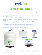
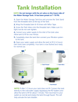
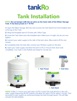
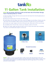
STORAGE TANK holds ltered water, ready for use.
AUTOMATIC SHUT-OFF VALVE senses when the
storage tank is full and closes the water supply to
conserve water.
The dedicated FAUCET is used to dispense RO produced
water when needed.
Feed water saddle valve is connected to the cold water
line to supply water to the R/O system.
WASTE WATER SADDLE VALVE is connected to the
drain to remove reject water from the R/O system.
TUBING supplies feed and reject water.
FITTINGS are used for necessary hose connections.
Tool s
The following tools may be necessary, depending on each
particular installation:
• 3/8” variable speed electric drill, 1/8” & 1/2” bits
• 1-1/4” porcelain hole cutter (if hole for second
• faucet is not provided
• Center punch and hammer
• 1-1/4” wood bit
• Concrete drill bits
• Phillips head and at blade screwdrivers
• Adjustable wrench
• Crescent wrench
• Te on tape
• Plastic tube cutter
• Air pressure gauge (low pressure)
• Air pump (hand)
System location
Your R/O system may be installed under a sink, in a
basement or other location, depending on available
space. Do not install unit where temperatures fall below
freezing; otherwise, damage will result. Connection to
an icemaker should also be considered for optimum
performance.
Guidelines for component placement are as follows:
FAUCET should be placed near the sink where drinking/
cooking water is normally required. A 2” at surface is
required to mount the faucet if an existing hole for
a second faucet is not available. The thickness of the
mounting thickness should not exceed 1-1/4”.
STORAGE TANK may be placed where it is convenient,
within ten feet of the faucet. Under the sink or in a
nearby cabinet are excellent choices. If tank is located
further than 10 feet from the faucet, use 1/2” tubing to
reduce pressure drop. Full tanks may weigh more than
thirty pounds, so a sturdy shelf is required.
R/O UNIT may be mounted on either side of the sink, in
a cabinet or heated basement, with nearby access to a
potable, cold water line.
Page 1 of 8

Installation Instructions
Residential Reverse Osmosis Drinking Water System
FEED WATER CONNECTION is accomplished with
a self-piercing feed water saddle valve. Locate this
assembly as close to the R/O unit as possible. Connect
to a potable, cold water supply line only.
NOTE: Softened water is preferred since it will extend the
life of your R/O membrane.
DRAIN CONNECTION is accomplished using a waste
water saddle valve which is designed to t around a
standard 1-1/2” OD drain pipe. The drain saddle valve
should always be installed above (before) the tap and
on the vertical or horizontal tailpiece.
Do not install the drain saddle valve near a garbage
disposal; otherwise, plugging of the waste water line
may occur. If discharging into a utility sink or standpipe,
an air gap must be provided. (Air gaps must be 1” or
greater above the oor rim.)
NOTE: Plumbing codes may require the use air gaps. Please
check with your local municipality.
Do not connect the R/O system drain line to the
dishwasher drain line due to the fact back pressures my
cause the air gap to over ow.
Site preparation
Installing dealers may want to speak with customers in
advance and ask them to clean under the sink to save
time. If a basement installation is advisable, check area
to determine if extra ttings or hosing are required.
Upon arrival, it is a good idea to check the condition of
all plumbing for potential leaks and advise customer so
there will be no misunderstandings in the event leaks
occur.
Unit preparation
Open shipping carton, remove components and check
that all parts are present. Check empty storage tank
to be sure air pressure is approximately 7 PSI. Adjust if
necessary.
Installation steps
NOTE: All plumbing must be completed in accordance
with state and local plumbing codes. Some municipalities
may require installation by a licensed plumber. Check
local authority prior to installation.
A. Faucet installation
If the sink has a sprayer it may be disconnected for
faucet installation. (Installing dealers should discuss this
with customers.) A pipe cap or plug will be necessary to
seal the sprayer connection.
To make the faucet mounting hole (if sprayer or second
hole is not used), check below to make sure the drill does
not interfere with anything below. Center punch a small
indent at the desired faucet location. (2” at surface is
required, not exceeding the chassis punch and tighten
nut to cut the desired hole size. Clean up sharp edges.
The faucet should be positioned so it empties into the
sink and the spout swivels freely for convenience. If sink
has a hole that can accommodate the RO faucet, no
drilling is required.
Proceed with mounting the faucet.
Porcelain, Enamel, Ceramic on Metal or Cast Iron
Precautions must be taken to penetrate the porcelain
through to the metal base and prevent it from chipping
or scratching.
Tools required:
• Variable speed drill
• Relton porcelain cutter tool set
(7/8” or alternative size, 9/16”)
• Plumber’s putty
Procedures
1. Mark the center for the 7/8” hole.
2. Form shallow putty around hole area and ll with
enough water to lubricate carbide drill bit.
3. Carefully drill pilot hole through all layers. (Use light
pressure and slow speed.)
4. Insert pilot tip of spring-loaded porcelain cutter into
pilot hole.
5. Drill porcelain/enamel using spring loaded porcelain
cutter, making certain a complete ring has been cut
through the porcelain / enamel to the metal base.
Page 2 of 8

Installation Instructions
Residential Reverse Osmosis Drinking Water System
6. Cut away the inner porcelain / enamel disc down
to the base metal. Make certain the cutter does
not touch outer rim of the cut porcelain / enamel.
Continue with his bit to cut through metal until sink
has been completely penetrated.
NOTE: Always use sharpened porcelain cutter to eliminate
chips and cracks.
Chrome base plate
Rubber washer
Threaded nipple
Flat washer
Star washer
Hex nut
Faucet adapter
Faucet installation without air gap
Installation procedures for stainless steel sinks
Recommended tools:
• Center punch
• Variable speed drill
• High speed drill bits
• Greenlee chassis punch 7/8”
(or 9/16” for non air gap faucets)
• Protective gloves & eye protectors
Procedures
1. Center punch small indent for hole.
2. Drill the required pilot hole.
3. Set-up the chassis punch per instructions and
tighten nut to cut the desired hole size.
4. Clean up sharp edges with le.
B. Mounting the faucet
Disassemble hardware from the threaded nipple, except
for chrome base plates and rubber washers. (Rubber
washers may be replaced with bead of plumber’s putty
for neater appearance.)
Feed the threaded nipple through sink or counter
mounting hole and orient the faucet. From below sink
or counter, assemble the white spacer at washer and
hex nut on threaded nipple and tighten by hand. (Open
end up; open side toward air gap). After checking faucet
orientation, tighten with a wrench until secure.
C. Feed water valve and tubing installation
The saddle tapping valve which is supplied is designed
for use with 3/8” to 1/2” OD soft copper supply tubing
(plain or chromed) and rigid metal pipe. Do not use
with exible ribbed supply tubing which is too thin and
requires special hardware.
Valve handle
Reversible
backplate
Tightening
screw
Tubing to
RO inlet
Compression
nut
Brass
insert
Plastic ferrule
Self-tapping feed water saddle valve installation
Installation procedures using soft copper tubing
1. Turn o cold water valve from under sink or main
water line valve for whole house.
2. Before installing saddle tapping valve, make sure
piercing lance does not protrude beyond rubber
gasket.
3. Assemble saddle valve on copper tubing.
4. Turn handle clockwise to pierce soft copper tube
until valve is rmly seated. (Valve is closed in this
position.)
5. Turn on water supply to pressure cold water line.
6. Snug nut/seal with wrench around valve stem.
7. Connect tubing to feed water valve using brass
compression nut, insert and plastic sleeve.
Page 3 of 8

Installation Instructions
Residential Reverse Osmosis Drinking Water System
Saddle valve installations with metal pipe:
1. Turn o cold water supply.
2. Drill 3/16” hole at desired location.
3. At this point, make sure piercing lance does not
protrude beyond rubber gasket.
4. Assemble saddle on to pipe, aligning with hole.
5. Turn saddle valve handle clockwise to close valve.
6. Tighten nut/seal around valve stem with wrench.
7. Connect tubing to feed water valve using brass
compression nut, insert and plastic sleeve.
8. Turn on cold water supply.
9. To open valve, turn handle counterclockwise and
check for leaks.
D. Drain saddle valve installation
Prior to proceeding it is important to inspect the
condition of drain pipes to make sure they are not thin
and frail.
Drain saddle valves are designed to be installed on
standard 1-1/2” OD drain pipe. Install drain saddle
valve above (and before) the trap and on the vertical or
horizontal tailpiece. Never install a drain saddle valve
close to the outlet of a garbage disposal or plugging of
the RO drain line may result.
1/4" Screw 1/4" Nut
Drain pipe
1/4" Drilled hole
Drain clamp
front plate
Drain saddle valve installation (brass insert)
Procedures
1. Position threaded half of drain saddle valve at
selected location and mark for the opening.
2. Drill 1/4” hole at mark through one side of pipe.
3. Position both halves of drain saddle on drain pipe so
threaded opening lines with hole.
4. Secure drain saddle clamp on valve with bolts and nuts
provided. (Do not over tighten and make sure there is
equal space between saddle halves on each side.)
E. Initial tubing connections
For convenience on under counter installations it may be
advisable to complete under counter hose connections
at this time.
F. R O co m po n en t i n s ta l la t io n
Install RO membrane, carbon pre- lter and sediment
pre- lter in modules of RO unit. (Refer to RO installation
diagram.)
G. RO unit installation
The RO unit is normally mounted to the right or left sink
cabinet sidewall, depending on where supply tank is to
be located. Generally the unit is installed at the front of
the cabinet and the tank at the rear.
To mount the unit, elevate it at least 2” o the oor, level
it and mark the location of mounting holes needed. Drill
holes for mounting screws and install screws, allowing
the mounting bracket slots to slip over them.
NOTE: If the cabinet sidewalls are not solid, unit may sit
on the oor with screws to keep it against the cabinet in a
vertical position.
H. Pre- ll, sanitizing and supply tank placement
Pre- lling the storage tank is always recommended
so there is su cient pressure to check for leaks and
su cient water to ush the carbon post lter.
It is important to use a sanitizer (such as Clorox) so
tubing, ttings, tank and the faucet will be safe to use
upon start-up.
To pre- ll storage tank follow these directions:
1. Connect storage tank to feed water line.
2. Open feed water valve and valve on tank.
3. Allow to ll for approximately three minutes.
4. Turn o feed water valve and tank valve.
5. Do not ush tank for approximately 15 minutes.
The supply tank should be placed under the counter
or within 10 feet of the RO unit.
Page 4 of 8

Installation Instructions
Residential Reverse Osmosis Drinking Water System
NOTE: Tanks are pre-pressurized at 7 psi. Prior to
installation, check, add or release as required.
I. Final tubing connections
With all components in place, complete nal tubing
connections using these guidelines:
• Tubing should follow contour of the cabinets.
• Cut tubing to desired length using square cuts
• and proper cutting devise.
• Make no sharp bends.
• Keep tubing from the RO unit to the tank and faucet
as short as practical for good ow.
Under sink installations following installation diagram
and the following procedures:
1. Connect tubing from faucet to RO unit.
2. Connect tubing from tank to RO unit.
3. Connect tubing from supply valve to RO unit.
4. Connect tubing from drain valve to RO unit.
Icemaker hookup (optional)
The RO drinking water device can be connected to
any standard refrigerator ice maker or ice maker/water
dispenser. (Do not connect to a commercial type bar ice
maker.)
To complete this operation, connect a tee with shuto
valve into the faucet tubing and route tubing to the
refrigerator. (Hooking up to an existing copper line is not
recommended unless it is new installation.) Shut o ice
maker by lifting lever prior to turning o the existing tap
water supply line to the refrigerator. Turn on ice maker
after the RO system has been drained several times and
the tank has a full supply of water.
NOTE: Before any service is preformed on the RO system,
turn o ice maker valve and ice maker unit. Turn back only
after RO tank is full.
System start-up
Prior to start-up
1. Check all connections to be sure they are secure.
2. Turn on feed water valve and check for leaks.
(Turn o and correct leaks if leaks occur.)
3. Open valve on storage tank and open faucet until a
steady stream of water ows.
4. Close faucet and wait ve minutes to see if leaks
result.
NOTE: When the system is rst turned on, water may
intermittently “spurt” from the air gap opening on the side
of air gap faucets. This is common and should correct itself
after an initial period of time.
Flushing system and checking operation
To make sure RO system is operating correctly, following
these simple procedures:
1. Open faucet handle and allow tank to completely
drain of sanitizing solution.
Do not use this water.
NOTE: When tank is empty, faucet will steadily drip. This is
the rate the RO system processes water.
2. With faucet handle in “open” position, measure the
rate of the steady drip from spout. Use a graduated
cylinder and watch with a second hand to calculate
approximate production in gallons per day.
NOTE: Milliliters per minute x 0.38 = GPD
Ounces per minute x 11.2 = GPD
3. Proceed to check reject ow rate by disconnecting
tubing at drain connection and measure ow as
described above.
NOTE: Proper ratio should be 3 reject water to 1 part of
product water, on average.
4. Close faucet and re-inspect system for leaks.
5. Allow system to process water for approximately
four hours, at which point tank will be practically
full.
6. Open faucet again and allow tank to empty for a
second time.
Do not use this water.
7. Wait another four hours to allow tank to re- ll.
NOTE: If no objectionable tastes are noticed after second
tank draining, RO processed water is ready for use.
Otherwise, drain tank and re- ll for a third time.
8. At this point supply line to ice maker connection
(optional) may be opened.
Maintenance
Your RO system contains lters and membranes
which must be replaced periodically for proper
operation. (Please see page 1 for general changeout
recommendations.)
NOTE: Change-out procedures may be amended,
depending on source water conditions.
Page 5 of 8

Installation Instructions
Residential Reverse Osmosis Drinking Water System
To change lters and membranes follow these procedures:
1. Close feed water valve by turning it clockwise.
2. Open faucet to allow holding tank to drain.
3. Loosen and remove lter housings using wrench
provided and discard cartridges and or membrane.
4. Wash the inside of the housings using mild
detergent and soft cloth. Thoroughly rinse all soap
before reassembly.
5. Replace lter cartridges and membrane before
sanitizing system.
NOTE: The system should be sanitized before installing the
activated carbon post lter cartridge.
Sanitizing instructions
To sanitize system follow these procedures with the
feed water valve closed:
1. Remove pre- lters and membrane from housings.
2. Use 5-1/4% unscented bleach such as Clorox.
3. Add one cap full (2 tsp or 10 ml) of bleach to each
pre- lter housing and membrane module.
4. Carefully re- ll housings with tap water and
temporarily replace WITHOUT carbon cartridge,
sediment cartridge or membrane installed.
5. Slowly open the feed water line at faucet.
6. Close faucet as soon as water begins to drip out of
spout.
7. Let system stand for approximately 15 minutes.
8. After fteen minutes do the following in order:
• Close feed water valve.
• Close holding tank valve while faucet is open
to release pressure.
9. Remove housings and empty them.
10. Remove any protective wrap from pre- lters and
membrane and install them in the appropriate lter
housings. Tighten with wrench.
11. Replace post carbon lter if necessary.
NOTE: Be sure to check o-rings are in place when installing
cartridges in lter housings.
12. Disconnect product water tubing from the holding
tank and put 50 drops of bleach into the tubing.
Reconnect tubing.
13. Slowly open feed water saddle valve. When water
begins to drip from faucet, close faucet and open
holding tank valve.
14. Do not open faucet for at least eight (8) hours.
15. Discard the rst two tanks of water produced, as
they contain chlorine. Do not use this water.
16. When faucet is rst opened, air and black carbon
powder may be noticed. This is normal.
Water quality
Water quality from an RO system is normally determined
with a TDS Meter, which measures total dissolved
solids in water, measuring conductivity. The results are
normally measured in parts per million or milligrams
per liter. Fewer dissolved solids results in higher quality
water.
RO membranes are rated by the amount of dissolved
solids they reject expressed as “rejection percentage”.
For example:
If feed water contains 100 ppm of dissolved solids and
the product water after the membrane has 10 ppm of
dissolved solids the rejection rate is 90%.
The formula is as follows:
Percent Rejection =
(Feed H
2
O TDS - Product H
2
O TDS) x 100%
Feed H
2
O TDS
Water production
PRODUCT WATER RATE
Usable water production from an RO system is
designated product water rate, produced on a daily
basis. The rate is normally described in gallons per day
(gpd) or milliliters per minute (ml/min).
REJECT WATER RATE
The ow of water to drain is designated as reject water
rate, as measured in gallons per day (gpd) or milliliters
per minute (ml/min).
Using a graduated cylinder the formulas are:
Milliliters per minute x 0.38 = gallons per day
Ounces per minute x 11.2 = gallons per day
REJECT RATIO
The reject ratio is the amount of water produced
compared to the amount of water owing to drain.
Page 6 of 8

Installation Instructions
Residential Reverse Osmosis Drinking Water System
Page 7 of 8
The formula is as follows:
Reject Ratio =
Reject Rate
Product Rate
PERCENT RECOVERY
The percent recovery is another way to measure the
amount of water produced compared to the amount of
water which is actually used.
The formula to determine percent recovery is as follows:
Percent Recovery =
Product H
2
O Rate x 100%
Feed H
2
O Rate
NOTE: Product water rate is the sum of the feed water ow
rate and reject water ow rate.
For example:
Product water rate =10 gpd
Reject water rate = 40 gpd
Feed water = (10 gpd + 40 gpd) or 50 gpd
Percent Recovery = 20%
Water pressure and temperature
Product water quality and production of RO systems is
dependent on pressure and temperature. Typically, RO
membranes are treated at standard conditions of 77°F
(25°C) and 60 psi (4 bar) discharging to atmosphere.
In general, the higher the pressure di erential and
temperature, the greater the quality and quantity of
water produced. These factors should be considered
when sizing RO systems for a particular application.
Quick Connect ttings
Many RO systems utilize Quick Connect ttings. These
user-friendly ttings provide superior performance
and may be provided with this system. Proper use of
these push-in ttings is shown below. Along with these
ttings, all tubing selected must be of high quality and
must be cut with a plastic tube cutter or sharp razor with
a clean, square cut.
Should a leak occur at a tting, the cause is generally
defective tubing. To x a leak, relieve pressure, release
tubing, cut o at least 1/4” from the end (square cut),
reattach the tubing and con rm the connection is leak
free. Each time a new connection is made, it is advisable
to cut o 1/4” from the end of the tubing using these
ttings.
Conventional compression ttings
If Quick Connect ttings are not used, it is essential to
install inserts at the ends of all tube connections when
conventional ttings are used.

Installation Instructions
Residential Reverse Osmosis Drinking Water System
Page 8 of 8
Spare Parts for Residential Reverse Osmosis Systems
TUBING
TO TANK
SHUT-OFF
VALVE FOR
TANK
TANK
POST CARBON FILTER
TO FAUCET
MEMBRANE HOUSING
AUTOMATIC
SHUT-OFF VALVE
ONE CARBON
BLOCK
PRE-FILTER
SEDIMENT
PRE-FILTER
SADDLE VALVE
FOR DRAIN
SADDLE VALVE
FOR SUPPLY
FLOW
CLIPS
CLIPS
BRACKET
SPARE PARTS
PART NUMBER DESCRIPTION QTY NEEDED
HF2-10WHWH14 NSF Listed 10” White Body, White Flat Cap ¼ ” 2
SDC-25-1005 Hydronix NSF Sediment Filter 2.5” x 9 7⁄8, 5 micron 1
CB-25-1005 Hydronix NSF Carbon Block Filter 2.5” x 9 7⁄8, 5 micron 2
ICF-10 Hydronix Inline Filter 2000 Gal., 2” x 10”, ¼ ” FNPT 1
RO-132-W14 4.5 Gallon White Tank 1/4” Stainless Steel 1
LF-BLR Low Lead LR 3” Shank, Chrome Plated 1
WNV-2 Adapter ½ ” F x ½ ” M x 1⁄8” F 1
DS-14QC Drain Saddle ¼ ” Quick Connect, Black 1
ASV-14QW Auto Shut-o Valve 1/4” Quick Connect, White 1
TW30-1812-50D TFC 50 GPD Membrane Dry 1
MH03-1812WH 1.8” x 12” Membrane Housing White 1
FM-60W Bracket White 14” W x 5.25” D x 2.3” H, Triple Housing, Bend Up 1
CLP-25W Membrane Housing Clip 2.5”, White 2
CLP-2520W Double Clip 2.5” x 2”, White 2
HDX4042 ¼ ” Tube x 1⁄8” Fixed Elbow NPT 2
HDX4044 ¼ ” Tube x ¼ ” Fixed Elbow NPT 1

I
nstallation Instructions
R
esidential Reverse Osmosis Drinking Water System
Fi
lter Change Instructions • Housing Care • Installation Instructions & Guidelines
1.
Turn o water supply to lter.
2. Depress release button (if present) to relieve pressure in lter housing.
3. Unscrew housing using lter wrench.
NOTE: When opening lter housing to change cartridge, it is common for O-ring/Gasket to lift out of housing and stick to cap.
4. Remove used cartridge and discard. Rinse out housing and ll about 1/3 full with water. Add about 2 to 3 tablespoons of bleach
and scrub thoroughly with brush or sponge. Rinse thoroughly.
5. Remove O-ring/Gasket from sump and wipe groove and O-ring/Gasket clean. Lubricate O-ring/Gasket with a coating of clean
silicone grease. Place O-ring/Gasket back in place and press O-ring down into the groove.
NOTE: This step is important to ensure proper lter seal. Make sure the O-ring is seated level in the groove (or gasket is on rim of
sump).
CAUTION: If O-ring/Gasket appears damaged or crimped it should be replaced at this time. See your local dealer for replacements
parts.
6. Insert a new cartridge into the sump making sure that it slips down over the sump standpipe.
7. Screw the sump onto the cap and hand tighten. DO NOT OVER-TIGHTEN. Make sure cartridge slips over the cap standpipe.
8. Turn on the water supply slowly to allow housing to ll with water.
9. Depress the pressure release button (if present) to release trapped air from lter.
10. Check for leaks before leaving installation.
WARNING: Do not use with water that is microbiologically unsafe or of unknown quality without adequate disinfection before or
after the unit.
NOTE: Activated carbon cartridges and carbon block cartridges may contain a small amount of carbon nes (very ne black powder)
and a new cartridge, after installation, should be ushed with su cient water to remove the nes before using the water.
Each time you use water from your ltered water tap for drinking or cooking purpose, it is recommended that you run ( ush) the
tap at least 10 seconds prior to using water. This is particularly important if the water tap is not used daily.
NOTE: Certain types of harmless bacteria will attack cellulose material. Cartridge containing cellulose may seem to disintegrate,
produce a “musty” odor, or form a black precipitate due to the bacteria. If you notice any of the above problems while using the
cellulose media cartridges, switch to a synthetic media cartridge or consult the manufacturer.
NOTE: Replacement cartridges have a limited service life. Changes in taste, color and ow of the water being ltered are signals that
replacement of the cartridge is or soon may be necessary.
CAUTION: Filter housing must be protected against freezing and extreme temperatures. Filter housings should not be in direct
contact with sunlight for a prolonged period of time since UV rays can make housings brittle. Pressure should always be measured
before installation and water pressure regulators should be installed in the main line or in front of the housing if water pressure
exceeds manufacturers’ maximum water pressure: 75 PSI. Installers should make sure lters and replacement lters are the correct
length and are not too long so as to not cause undo strain and stress on the housing. A leak detector must be installed on all
installations where high pressure, water hammer and pressure spikes are known or suspected to be present and on all installations
where pressure is over 60 PSI. Failure to the above may result in cracking of the lter housing, water leakage and water damage.
CAUTION: All ltration systems contain other parts that have a limited service life.
Exhaustion of the service life of those parts often cannot be easily detected. Commonly, it is only after leakage has been observed
or water damage has occurred that one is made aware that the service life has been exhausted.
IMPORTANT NOTICE: To prevent costly repairs or possible water damage we strongly recommend that the bowl or sump of all
plastic housings be replaced periodically: every 5 years for clear sumps, and every 4 years for opaque sumps. If your sump has been
in use for more that the recommended period, it should be replaced immediately. Be sure to date any new or replacement sump
for future reference and indicate the next recommended replacement date.
WARRANTY: Limited three (3) year warranty for material defects only. Warranty is limited to repair or replacement of product only.
Any misuse, misinstallation, lack of maintenance, exceeding maximum pressure or failure to follow these instructions will void
limited warranty.

GALAXY
4 STAGE
TWO YEAR COVERAGE
For two (2) years to the original purchaser, at the original
residential place of installation of this Galaxy Series 4 Stage
Reverse Osmosis Drinking Water Purification System, US
WATER SYSTEMS, INC. warrants the following:
Storage Tank
RO Module
Free of all costs to you except transportation and labor charges,
we warrant that we will replace or repair the storage tank, filter
housings, and membrane housing, if for any reason it is found to
be defective, because of faulty materials or workmanship.
ONE YEAR COVERAGE
All Other Parts
We warrant that for one (1) year from the date of installation, we
will replace any part not listed above at no charge to you except
for transportation and standard labor charges, except the
following items:
Pre Filters
Post Filter
Reverse Osmosis Membrane
GALAXY
5 STAGE
TWO YEAR COVERAGE
For two (2) years to the original purchaser, at the original
residential place of installation of this Galaxy Series 5 Stage
Reverse Osmosis Drinking Water Purification System, US
WATER SYSTEMS, INC. warrants the following:
Storage Tank
RO Module
Free of all costs to you except transportation and labor charges,
we warrant that we will replace or repair the storage tank, filter
housings, and membrane housing, if for any reason it is found to
be defective, because of faulty materials or workmanship.
ONE YEAR COVERAGE
All Other Parts
We warrant that for one (1) year from the date of installation, we
will replace any part not listed above at no charge to you except
for transportation and standard labor charges, except the
following items:
Pre Filters
Post Filter
Reverse Osmosis Membrane
GENERAL PROVISIONS
This warranty does not apply to any commercial or industrial
installations or to any part of the reverse osmosis system which
has been subjected to misuse, neglect, alteration or accident; or
to any damage caused by fire, flood, freezing, Acts of God, or any
other casualty, or if said system is damaged by anyone, or if the
original serial numbers have been removed. Fouling or damage
to the membrane or filters caused by iron, sulfur, bacterial iron,
silt, sand, tannins, organics, bacteria, hot water or chlorine voids
the warranty on the membrane..
These warranties are in lieu of all other warranties expressed or
implied, and we do not authorize any person to assume for us any
other obligation on the sale of this water conditioner. No
responsibility is assumed for delays or failure to meet these
warranties caused by strike, government regulations or other
circumstances beyond the control of US WATER SYSTEMS, INC.
TO OBTAIN WARRANTY SERVICE, CALL OR WRITE: US WATER
SYSTEMS, INC. 1209 COUNTRY CLUB ROAD
INDIANAPOLIS, IN 46234 (317) 209-0889 OR 800-608-8792.
ANY IMPLIED WARRANTIES OF FITNESS OR
MERCHANTABILITY ARE LIMITED TO THE TERMS OF THIS
EXPRESSED WARRANTY AND THERE ARE NO WARRANTIES
WHICH EXTEND BEYOND THOSE HEREIN. US WATER
SYSTEMS, INC. SHALL NOT BE LIABLE WHATSOEVER FOR
ANY INCIDENTIAL AND/OR CONSEQUENTIAL DAMAGES.
SOME STATES DO NOT ALLOW THE EXCLUSION OR
LIMITATIONS OF INCIDENTAL OR CONSEQUENTIAL
DAMAGES SO THE ABOVE LIMITATION MAY NOT APPLY TO
YOU. THIS WARRANTY GIVES YOU SPECIFIC LEGAL
RIGHTS, AND YOU MAY ALSO HAVE OTHER RIGHTS WHICH
VARY FROM STATE TO STATE.
THIS WARRANTY MAY BE TRANSFRRED TO A SUBSEQUENT
OWNER WITH WRITTEN APPROVAL OF US WATER
SYSTEMS, INC. AND PAYMENT OF STANDARD TRANSFER
FEE.
FOR YOUR RECORDS:
Model__________________________________________
Serial __________________________________________
Date Installed ___________________________________
/