TLI Pro 201 and TLSI 201 • Setup Guide (Continued)
Connect the Ethernet cable. The interface must be powered by PoE+.
ATTENTION:
• Do not power on the TLI Pro 201 or TLSI 201 until you have read the Attention in the Rear Panel Features section of
the TLI Pro 201 User Guide.
• Ne branchez pas le TLI Pro 201 ou le TLSI 201 avant d’avoir lu la mise en garde dans la section «Rear Panel
Features» du TLI Pro 201 UserGuide.
Set up the Interface for Network Communication
Connect the PC that you will use for setup on the same Ethernet subnetwork as the interface. If you are using the
TLI Pro 201, you must also connect a control processor to the same subnetwork. The TLSI 201 does not require a control
processor.
Use the Setup Menu (see page 4) or Toolbelt to set the DHCP status and, if necessary, the IP address, subnet mask,
gateway, and related settings for the network interface.
Configure the User Interface
TLI Pro 201 — The Global Configurator Professional Help File, the Global Configurator Plus Help File, and the GUI Designer
Help File provide step-by-step instructions and more detailed information. The Global Congurator Professional and Global
Congurator Plus help les include an introduction to the software and sections on how to start a project and conguration.
TLSI 201 — Use Room Agent to congure the TLS touchpanels. For complete instructions about conguring the TLSI 201, see
the Room Agent Help File, User Guide, and Quick Start Guide at www.extron.com.
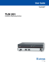
Rear Panel Connectors and Features
The TLI Pro 201 and TLSI 201 have identical rear panels. For complete information about the rear panel connectors and features,
see the TLI Pro 201 and TLSI 201 User Guide.
USB LAN/PoE
+
OUTPUTINPUT
Figure 1. TLI Pro 201 Rear Panel
ATTENTION:
• The TLI Pro 201 and TLSI 201 are Power over Ethernet (PoE 803.3at, class4) compliant. Do not connect the power
supply before reading the Attention in the Rear Panel Features section of the TLI Pro 201 and TLSI 201 User Guide.
• Le TLI Pro 201 et le TLSI 201 supportent l’alimentation via Ethernet (PoE 803.3at, classe4). Veuillez lire la partie
« Attention » dans la section « Rear Panel Features » du TLI Pro 201 and TLSI 201 User Guide, avant de mettre sous
tension les écrans tactiles.
gure 1
A
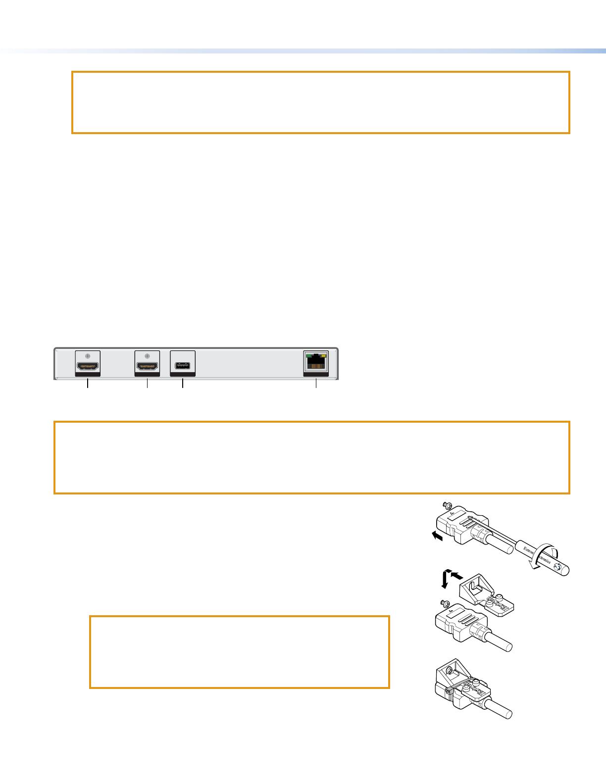
HDMI input (TLI Pro 201 only) — Plug the cable from the input source device
into this female HDMI type A port. Use the provided LockIt HDMI lacing bracket
to secure the HDMI connector:
1. Plug the HDMI cable into the panel connection.
2. Loosen the HDMI connection mounting screw from the panel enough to
allow the LockIt lacing bracket to be placed over it. The screw does not
have to be removed.
3. Place the LockIt lacing bracket on the screw and against the HDMI
connector, then tighten the screw to secure the bracket.
ATTENTION:
• Do not overtighten the HDMI connection mounting screw. The
shield it fastens to is very thin and can easily be stripped.
• Ne serrez pas trop la vis de montage du connecteur HDMI. Le
blindage auquel elle est attachée est très n et peut facilement
être dénudé.
4. Loosely place the included tie wrap around the HDMI connector and the
LockIt lacing bracket as shown.
5. While holding the connector securely against the lacing bracket, tighten the
tie wrap, then remove any excess length.
HDMI input
3
1
1
2
2
3
3
4
4
5
5
Figure 2. Securing the HDMI Connector