
1
Product Category
IMPORTANT:
Go to for the
complete user guide and installation
instructions before connecting the
product to the power source.
TLSI 201 • Setup Guide
Overview
The Extron TLSI 201 Interactive Waynding Interface provides real-time meeting space availability, status, and location
information using a centralized display. The TLSI 201 communicates over the Ethernet network directly with Extron TLS
room scheduling panels and shows information about the Touchlink scheduler system on third-party touch and non-touch
displays. Users can locate and book meeting spaces for the day or week on an interactive grid or map with ease. No additional
programming or external processors are required.
This guide provides instructions for experienced installers to mount and install the TLSI 201 and to create a basic conguration.
For more complete instructions, see the TLSI 201 User Guide, at www.extron.com.
Setup Checklist
Get Ready
Download and install the latest version of the following software:
Room Agent™ — Room booking software for conguring the TLSI 201 for room scheduling. Room Agent can be
downloaded (free of charge) from www.extron.com.
Obtain the following network information from your network administrator:
DHCP status — (on or off). If DHCP is off, you must also obtain:
IP address Subnet mask Gateway
User name — This can be either admin or user.
Password — The factory congured passwords for all accounts on this device have been set to the device serial
number. Passwords can be changed during conguration. They are case sensitive.
NOTE: If the device is reset to default settings, the passwords are reset to the default password, which is extron
(for either admin or user).
Make a note of the MAC address for the TLSI 201.
Mount and Cable All Devices
Mount the units. The TLSI 201 can be discretely mounted behind a at panel display. Other mounting options are also
available (see the TLSI 201 product page at www.extron.com).
To mount the third-party touchpanel follow the instructions provided by the manufacturer.
Connect cables to the TLSI 201 (see Rear Panel Connectors and Features on the next page).
Connect the HDMI output from the TLSI 201 to the third-party touchpanel.
Connect the USB port from the TLSI 201 to the third-party touchpanel.
NOTE: The USB connection passes information to the TLSI 201 about where on the screen the third-party touch
display was pressed. If using a non-touch display, connect a USB mouse to the USB port on the TLSI 201 to click
screen icons.
Connect the Ethernet cable. The TLSI 201 must be powered by PoE+.
ATTENTION:
• Do not power on the TLSI 201 until you have read the Attention in the Rear Panel Features section of the TLSI 201
User Guide.
• Ne branchez pas le TLSI 201 avant d’avoir lu la mise en garde dans la section «Rear Panel Features» du TLSI 201
UserGuide.
Set up the TLSI 201 for Network Communication
Connect the PC that you will use for setup on the same Ethernet subnetwork as the TLSI 201.
Use the Setup Menu (see page 4) to set the DHCP status and, if necessary, the IP address, subnet mask, gateway, and
related settings for the network interface.
Configure the User Interface
Use Room Agent to congure the TLSI 201 (see the Room Agent User Guide and Room Agent Quick Start Guide at
www.extron.com, or the Room Agent Help File).
www.extron.com

TLSI 201 • Setup Guide (Continued)
2
Rear Panel Connectors and Features
For complete information about the rear panel connectors and features, see the TLSI 201 User Guide.
AAABBBC
CCD
DD
DEVICE LAN/PoE
+
OUTPUTINPUT
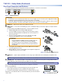
Figure 1. TLSI 201 Rear Panel
ATTENTION:
• The TLSI 201 is Power over Ethernet (PoE 803.3at, class4) compliant. Do not connect the power supply before reading
the Attention in the Rear Panel Features section of the TLSI 201 User Guide.
• Le TLSI 201 support l’alimentation via Ethernet (PoE 803.3at, classe4). Veuillez lire la partie « Attention » dans la section
« Rear Panel Features » du TLSI 201 User Guide, avant de mettre sous tension les écrans tactiles.
A
HDMI input — At present, this port is not used by the TLSI 201.
B
HDMI output — Connect this female HDMI type A port to a third-party display. The TLSI 201 supports an output resolution
of 1080p.
gure 1
HDMI input
Use the provided LockIt HDMI lacing bracket to secure the HDMI connector:
1. Plug the HDMI cable into the TLSI 201 HDMI output port.
2. Loosen the HDMI connection mounting screw from the panel enough to
allow the LockIt lacing bracket to be placed over it. The screw does not
have to be removed.
3. Place the LockIt lacing bracket on the screw and against the HDMI
connector, then tighten the screw to secure the bracket.
ATTENTION:
• Do not overtighten the HDMI connection mounting screw. The
shield it fastens to is very thin and can easily be stripped.
• Ne serrez pas trop la vis de montage du connecteur HDMI. Le
blindage auquel elle est attachée est très n et peut facilement
être dénudé.
4. Loosely place the included tie wrap around the HDMI connector and the
LockIt lacing bracket as shown.
5. While holding the connector securely against the lacing bracket, tighten the
tie wrap, then remove any excess length.
3
1
1
1
2
2
2
3
3
3
4
4
4
5
5
5
Figure 2. Securing the HDMI Connector
C
DEVICE port — supports High-speed USB 2.0 control. Plug a Type-A USB cable from the third-party touchpanel into this
port.
NOTE: If using a non-touch display, connect a USB mouse to the USB port on the TLSI 201 to click screen icons.
D
LAN/PoE+ port — Use an Ethernet cable to connect this port to the network via a PoE+ power sourcing equipment (PSE,
not provided). This can be a power injector (see gure 3) or PoE+ switch.
NOTE: The TLSI 201 does not include any PoE+ power sourcing equipment. This must be purchased separately.
Extron recommends the Extron PI 140 power injector (see gure 3). Your power
injector may look different.
1. Use an Ethernet cable to connect the LAN/PoE+ port of the TLSI 201 to the
power output of the 803.3at, class4 compliant PoE+ power injector.
2. Connect the network input of the power injector to a network switch or router.
Alternatively, use an Ethernet cable to connect the LAN/PoE+ port of the TLSI 201 to
a PoE+ switch.
100-240V
50/60 Hz
1.1A MAX
INPUT
LAN POWERED TLP
OUTPUT
To network switch
To interface
Figure 3. PI 140 Power Injector
gure 3

3
Product Category
Front Panel Features
SIGNAL
INPUTOUTPUT
HDCP
TLSI 201
R MENU
AAABBBCCCDDD
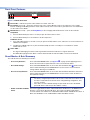
Figure 4. TLSI 201 Front Panel
A
Power LED — Indicates the power status and the reset status of the unit.
B
Reset button (recessed) — allows the unit to be reset in any of three different modes. It also allows the user to toggle
between enabling and disabling the DHCP client. A brief summary of the reset modes is given below. For more information
see the TLSI 201 User Guide.
C
Menu button (recessed) — opens the Setup Menu (see the next page) and Calibration screen for the TLSI 201:
Setup Menu
1. Press the button briey (less than 3 seconds) to open the internal menu screens.
2. Press the button briey for a second time to exit the setup menu.
Calibration Screen
1. Press and hold the button (3 seconds or more) to open the Calibration screen. Follow the on-screen instructions to
calibrate the touchpanel.
2. Complete the calibration process or press the button briey (less than 2 seconds) for a second time to exit the
Calibration screen.
D
Status LEDs —
• The Signal LEDs light green when a video signal is detected and are unlit when no signal is detected.
• The HDCP LEDs light green when HDCP content is detected and are unlit when HDCP content is not detected.
Reset Modes: A Brief Summary
The TLSI 201 offers the following reset modes:
• Use Factory Firmware:
Press and hold the
Reset button (see figure 4,
B
, on page 3) while applying power to
the unit. Use this mode to replace rmware in the event of rmware failure.
• Reset All IP Settings:
Press and hold the
Reset button for 6 seconds. After the Power LED (
A
) ashes twice,
release and momentarily press the Reset button. Use this mode to reset all network
settings without affecting user-loaded les.
• Reset to Factory Defaults:
Press and hold the
Reset button for 9 seconds. After the Power LED ashes three times,
release and momentarily press the Reset button. Use this mode to return the device to
factory default settings.
NOTES:
• The factory congured passwords for all accounts on this device have been set to
the device serial number. Passwords can be changed during conguration. They
are case sensitive.
• If the device is reset to default settings, the passwords are reset to the default
password, which is extron (for either admin or user).
• Enable or Disable the DHCP
Client:
This mode toggles between DHCP enabled and DHCP disabled. Press the
Reset button
ve times, consecutively. After the fth press, do not press the button again within 3
seconds. If DHCP was enabled, it is now disabled and the Power LED blinks three times. If
DHCP was disabled, it is now enabled and the
Power LED blinks six times.
gure 4

4
68-3514-51 Rev. A
04 20
TLSI 201 • Setup Guide (Continued)
For information on safety guidelines, regulatory compliances, EMI/EMF compatibility, accessibility, and related topics, see the
Extron Safety and Regulatory Compliance Guide on the Extron website.
© 2020 Extron Electronics — All rights reserved. www.extron.com
All trademarks mentioned are the property of their respective owners.
Worldwide Headquarters: Extron USA West, 1025 E. Ball Road, Anaheim, CA 92805, 800.633.9876
Setup Menu
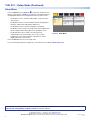
Press the Menu button (see figure 4,
C
) to open the setup menu (see
gure 5). There are ve available screens that are selected by pressing
the appropriate button in the navigation bar at the top of the screen.
• The Status screen is read-only and provides a summary of the
other screens.
• The Network screen is used to edit the network settings (DHCP
setting, IP, subnet mask and gateway addresses).
• The Display screen is used to congure the sleep timer.
• The Audio screen is used to set audio levels for the audible clicks
that accompany buttons being pressed on the display screen.
• The Advanced screen is used to set a PIN to prevent
unauthorized access to the setup menu. It is also used to
congure the mouse if the TLSI 201 is attached to a normal
display rather than a touchscreen.
Info
Model: TLSI 201
Part Number: 60-1669-01
Firmware
Version:
1.00
Network
IP Address:
DHCP:
Host Name:
Off
192.168.254.251
TLSI-AB-CD-EF
Display
Resolution:
Sleep Timer:
1920x1080
Off
Audio
Click Volume:
Click Mute: Off
99
Status
Display
Audio
Advanced
Exit
Network
Bootloader
Version:
1.00
Advanced
Menu PIN: Disabled
Figure 5. Setup Menu
Press the
Exit button to close the setup menu.
For more information about the setup menu, see the TLSI 201 User Guide at www.extron.com.
-
 1
1
-
 2
2
-
 3
3
-
 4
4


Ask a question and I''ll find the answer in the document
Finding information in a document is now easier with AI
in other languages
- français: Extron TLSI 201 Manuel utilisateur
Related papers
-
Extron electronics TLI Pro 201 User manual
-
 Extron electronics TLSI 201 User manual
-
Extron TLSI 201 User manual
-
-
-
-
-
 Extron electronics TLI Pro 101 User manual
-
 Extron electronics FOX3 T 201 User manual
-
 Extron electronics FOX3 T 201 User manual


