Page is loading ...

CDHD Servo Drive
User Manual
Revision 0.2
PRELIMINARY RELEASE


CDHD
User Manual i
Revision History
Document
Revision
Date Remarks
0.2 June 2011
Added diagram: CDHD-1D5 Dimensions;
Replaced diagram: System Wiring - Pin
Assignments; Minor text fixes
0.1 June 2011 Preliminary version
Hardware
Revision
Firmware
Revision
Software
Revision
Remarks
0.0.0.10
Important Notice
© 2011 Servotronix Motion Control Ltd.
All rights reserved. No part of this work may be reproduced or transmitted in any
form or by any means without prior written permission of Servotronix Motion
Control Ltd.
Disclaimer
The information in this manual was accurate and reliable at the time of its
release. Servotronix Motion Control Ltd. reserves the right to change the
specifications of the product described in this manual without notice at any time.
Trademarks
All marks in this manual are the property of their respective owners.
Contact Information
Servotronix Motion Control Ltd.
21C Yagia Kapayim Street
Petach Tikva 49130
Israel
Tel: +972 (3) 927 3800
Fax: +972 (3) 922 8075
Website:
www.servotronix.com
Technical Support
If you need assistance with the installation and configuration of the CDHD drive,
contact Servotronix technical support:
tech.support@servotronix.com
Customer Service
Servotronix is committed to delivering quality customer service and support for
all our products. Our goal is to provide our customers with the information and
resources so that they are available, without delay, if and when they are needed.
In order to serve in the most effective way, we recommend that you contact
your local sales representative for order status and delivery information, product
information and literature, and application and field technical assistance. If you

CDHD
ii Servotronix
are unable to contact your local sales representative for any reason, please use
the most relevant of the contact details below:
For technical support, contact:
tech.support@servotronix.com
To order products, contact:
orders@servotronix.com
For all other inquiries regarding CDHD drives or other Servotronix products,
contact: customer.service@servotronix.com
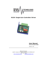
Part Number
For ordering the CDHD, refer to the following diagram:
Warranty
The warranty is valid for 12 months from the date of shipment and applies only if
material or workmanship is found to be defective. The warranty will be invalid if
the customer fails to install, operate or maintain the product in accordance with
the instructions in this user manual.
During the warranty period, the owner must pay the cost of shipping the product
to the factory for repair, and Servotronix will pay for shipping the repaired
product to the customer.
After the warranty period has expired, all shipping costs will be the responsibility
of the customer.
Before returning the product, the customer must first request a Return Materials
Authorization (RMA) number from Servotronix by email to rma@servotronix.com
The complete Warranty Statement can be found in the Terms and Conditions
document on the Servotronix website:
www.servotronix.com/customer-service.html

CDHD
User Manual iii
Contents
1 Introduction ________________________________________________ 1
1.1 Documentation .......................................................................................... 1
1.1.1 About This Manual ............................................................................ 1
1.1.2 Documentation Set for CDHD ............................................................. 1
1.2 Safety ...................................................................................................... 1
1.2.1 Safety Symbols ................................................................................ 1
1.2.2 Safety Instructions ........................................................................... 2
1.3 Standards Compliance ................................................................................ 2
1.3.1 General Information ......................................................................... 2
1.3.2 CE Compliance ................................................................................. 3
1.4 Unpacking................................................................................................. 4
2 Product Description __________________________________________ 5
2.1 Overview .................................................................................................. 5
2.1.1 General Description .......................................................................... 5
2.1.2 Product Options ............................................................................... 5
2.2 Technical Specifications .............................................................................. 6
2.2.1 Dimensions ..................................................................................... 6
2.2.2 Mechanical and Electrical Specifications - 200V .................................... 7
2.2.3 Mechanical and Electrical Specifications - 400V .................................... 8
2.2.4 Control Specifications ...................................................................... 10
2.2.5 Protective Functions and Environment................................................ 11
2.2.6 Communication ............................................................................... 11
2.2.7 I/Os............................................................................................... 12
2.2.8 Motor Feedback............................................................................... 13
2.3 System Wiring - Pin Assignments ................................................................ 14
3 Installation ________________________________________________ 15
3.1 Installation Overview ................................................................................ 15
3.2 Preparation .............................................................................................. 15
3.2.1 Hardware Requirements ................................................................... 15
3.2.2 Computer Requirements................................................................... 16
3.2.3 Electrical Requirements .................................................................... 18
3.3 Mechanical Installation .............................................................................. 20
3.3.1 Mount the CDHD ............................................................................. 20
3.4 Electrical Installation ................................................................................. 20
3.4.1 Connect Motor (P2) ......................................................................... 20
3.4.2 Connect STO (P1)............................................................................ 21
3.4.3 Connect Regen (P3) ......................................................................... 22
3.4.4 Connect Motor Feedback (C4) ........................................................... 22
3.4.5 Connect Controller I/Os (C2) ............................................................ 24
3.4.6 Connect Machine I/Os (C3) ............................................................... 25
3.4.7 Connect AC Input Voltage (P4).......................................................... 26
3.5 Set the Drive Address................................................................................ 27
3.6 Connect to PC (C1 or C7) ........................................................................... 28
3.7 Power Up ................................................................................................. 29
3.8 ServoStudio Software Installation ............................................................... 29
4 Configuration and Operation___________________________________ 30
4.1 Variables and Commands........................................................................... 30
4.2 ServoStudio Software ................................................................................ 30
4.3 Connecting to a Drive ................................................................................ 31
4.4 Enabling/Disabling a Drive ......................................................................... 31
4.4.1 Drive Enable ................................................................................... 31
4.4.2 Operation Mode Codes ..................................................................... 32

CDHD
iv Servotronix
4.5 Managing Drive Parameters ....................................................................... 33
4.6 Configuring Parameters Using ServoStudio .................................................. 34
4.6.1 Tuning and Testing .......................................................................... 34
4.6.2 Drive Info ....................................................................................... 35
4.6.3 Power ............................................................................................ 35
4.6.4 Motor ............................................................................................. 35
4.6.5 Foldback ........................................................................................ 35
4.6.6 Units.............................................................................................. 35
4.6.7 Feedback ....................................................................................... 35
4.6.8 Motion ........................................................................................... 36
4.6.9 Scope ............................................................................................ 36
4.6.10 Digital I/Os ..................................................................................... 36
4.6.11 Analog I/O...................................................................................... 36
4.6.12 Enable ........................................................................................... 36
4.6.13 Current Loop .................................................................................. 36
4.6.14 Current Limits ................................................................................. 36
4.6.15 Velocity Loop .................................................................................. 36
4.6.16 Velocity Limits ................................................................................ 36
4.6.17 Terminal ........................................................................................ 36
4.6.18 Faults ............................................................................................ 37
4.6.19 Parameters Table ............................................................................ 37
4.7 ServoStudio Expert View ........................................................................... 37
5 Firmware Upgrade __________________________________________ 38
5.1 Preparation .............................................................................................. 38
5.2 Upgrade Procedure ................................................................................... 38
6 Troubleshooting ____________________________________________ 39
6.1 Drive Status 7-Segment Display ................................................................. 39
6.2 Faults and Warnings .................................................................................. 39
6.3 Status Information in ServoStudio .............................................................. 40
6.4 Fault and Status Queries ........................................................................... 40
6.5 Fault Codes and Names ............................................................................. 40

CDHD Introduction
User Manual 1
1 Introduction
1.1 Documentation
1.1.1 About This Manual
This manual describes the Servotronix CDHD Servo Drive. It provides the
information required for installation, configuration and basic operation of the
CDHD unit.
This document is intended for persons who are qualified to transport, assemble,
commission, and maintain the equipment described herein.
1.1.2 Documentation Set for CDHD
This manual is part of a documentation set. The entire set consists of the
following:
CDHD Quick Start Guide. Basic setup and operation of the drive.
CDHD User Manual. Hardware installation, configuration and operation.
CDHD VarCom Reference Manual. Parameters and commands used to
program the CDHD.
1.2 Safety
Only qualified persons may perform the installation procedures. You do not need
to be an expert in motion control to install and operate the drive system.
However, you must have a basic understanding of electronics, computers,
mechanics, and safety practices.
The CDHD utilizes hazardous voltages.
Be sure the drive is properly grounded.
Before you install the CDHD, review the safety instructions in this manual.
Failure to follow the safety instructions may result in personal injury or
equipment damage.
1.2.1 Safety Symbols
Safety symbols indicate a potential for personal injury or equipment damage if
the recommended precautions and safe operating practices are not followed.
The following safety-alert symbols are used on the drive and in the
documentation:
Caution ISO 7000-0434 (2004-01)

Introduction CDHD
2 Servotronix
Warning. Dangerous voltage. IEC 60417-5036 (2002-10)
Protective earth; protective ground IEC 60417–5019 (2006-08)
Caution, hot surface IEC 60417-5041 (2000-10)
1.2.2 Safety Instructions
Read all available product documentation before assembling and
commissioning. Incorrect handling of this product may cause personal injury
and/or damage to equipment. Adhere strictly to the installation instructions
and requirements.
All system components must be connected to ground. Electrical safety is
provided through a low-resistance earth ground connection.
This product contains static sensitive components that can be damaged by
incorrect handling. Avoid contact with high insulating materials (artificial
fabrics, plastic film, etc.). Place the product on a conductive surface. Ground
yourself (discharge any possible static electricity build-up) by touching an
unpainted, metal, grounded surface.
Keep all covers and cabinet doors shut during operation. Otherwise,
potential hazards may cause personal injury and/or damage to equipment.
During operation the product has electrically charged components and hot
surfaces. The heat sink can reach temperatures of 90°C. Control and power
cables can carry a high voltage, even when the motor is not rotating.
To avoid electric arcing and hazards to personnel and electric contacts,
never disconnect or connect the product while the power source is
energized.
After removing the power source from the equipment, wait at least
5 minutes before touching or disconnecting sections of the equipment that
normally carry electrical charges (e.g., capacitors, contacts, screwed
connections). For safety, measure the electrical contact points with a meter
before touching the equipment. Wait until the voltage drops below 30 VAC
before handling components.
1.3 Standards Compliance
1.3.1 General Information
The CDHD has been successfully tested and evaluated according to standards
IEC 61800-5-1 and UL 508C. This testing outlines the minimum requirements for
electrically operated power conversion equipment (frequency converters and
servo amplifiers), which are intended to eliminate the risk of fire, electric shock,
or injury to persons.

CDHD Introduction
User Manual 3
UL 508C references UL 840, which describes the achievement by design of air
and insulation creepage spacings for electrical equipment and printed circuit
boards. The CDHD provides overload protection and current limit control.
The drive is intended for operation in pollution level 2 environment.
The terminals on the controller are coded so they can easily be identified in the
instructions. The instructions identify the connections for the power supply, load,
control, and ground.
Integral solid state short circuit protection does not provide branch circuit
protection. Branch circuit protection must be provided in accordance with the
National Electrical Code and any additional local codes, or the equivalent.
1.3.2 CE Compliance
Compliance with EC EMC Directive (2004/108/EC) and EC Low Voltage Directive
(2006/95/EC) is mandatory for all servo drives provided to the European
Community. CDHD is manufactured in conformance with these directives. CDHD
drives have also been successfully tested and evaluated to the limits and
requirements of these directives.
EC Low Voltage Directive (2006/95/EC) complies with standard IEC 61800-5-1.
The following standards are used in connection with EC EMC Directive
(2004/108/EC):
IEC 61000-6-1/2 (Interference Immunity in Residential & Industrial Areas)
IEC 61000-6-3/4 (Interference Generation in Residential & Industrial Areas)
Drives are components that are intended for incorporation into a machine, for
industrial use. Before a drive is in installed, verify that the associated equipment
complies with the following standards:
EC Machinery Directive (2006/42/EC)
EC EMC Directive (2004/108/EC)
EC Low Voltage Directive (2006/95/EC)
Standards EN/IEC 60204-1 (Safety and Electrical Equipment in Machines),
ISO 12100 (Safety of Machines) and EN 292 must be observed in reference to
Machinery Directive (2006/42/EC).
Standard IEC 60439-1 (Low-voltage Switchgear and Control Gear Assemblies)
must be observed in reference to EC Low Voltage Directive (2006/95/EC).
The machine manufacturer must generate a hazard analysis for the machine,
and must implement suitable measures to ensure that unexpected movements
will not cause personal injury and/or property damage.
The machine manufacturer is responsible for ensuring that the machine meets
the requirements specified by the EMC regulations. Guidelines for correct
installation for EMC (such as shielding, grounding, treatment of connectors and
cable layout) are provided in this.
The machine manufacturer must check whether EC Directives or other standards
must be applied to the machine.
Servotronix only guarantees the conformance of the servo system with the
standards cited in this chapter.

Introduction CDHD
4 Servotronix
Caution: Installation of the equipment is critical in designing system and
machine electromagnetic compatibility (EMC).
The end user must apply the installation recommendations in this manual.
1.4 Unpacking
1. Open the package(s) and remove all packing materials and items. The
package contains two items:
• The CDHD drive
• A packet of mating connectors for the power connectors.
2. Check to ensure there is no visible damage to any of the equipment. If
damage is detected, notify the carrier immediately.

CDHD Product Description
User Manual 5
2 Product Description
2.1 Overview
2.1.1 General Description
The CDHD is a full-featured, high-performance servo drive featuring innovative
technologies and industry-leading power density.
Key features of the CDHD include:
Support for rotary and linear brushless DC motors, and DC brush motors.
Operation in current, velocity and position control loops.
Eleven digital inputs, six digital outputs, together with an analog input and
output, to meet any I/O requirement.
Various communication options.
Various motor feedback options.
Firmware customization to address special application requirements.
OEM motors predefined in user interface to enable immediate integration.
2.1.2 Product Options
The CDHD product family offers a number of options:
200 or 400 VAC rating
Continuous current of 1.5, 3, 6 or 13 A rms for the 200 V models
Continuous current of 3 or 6 A rms for the 400 V models
One 16-bit or two 14-bit analog inputs
Various interface options, including analog voltage/pulse train and CANopen.
Refer to the part number diagram at the beginning of this manual for the various
ordering options for the CDHD drive.

Product Description CDHD
6 Servotronix
2.2 Technical Specifications
2.2.1 Dimensions
The exterior dimensions of the CDHD-1D5 and CDHD-006 are shown in
Figure 2-1 and Figure 2-1, respectively
Figure 2-1. CDHD-1D5 Dimensions (in mm)
Figure 2-2. CDHD-006 Dimensions (in mm)

CDHD Product Description
User Manual 7
2.2.2 Mechanical and Electrical Specifications - 200V
Single and Three-
Phase 200V
Specification
CDHD-
1D5
CDHD-
003
CDHD-
006
CDHD-
013
Ratings
Input Power Main Circuit
(L1, L2, L3)
Voltage (VAC Line-Line) Nominal
±10%
110 to
230
110 to
230
110 to 230 110 to 230
115 VAC 1 Phase 1 Phase
1 Phase or
3 Phase
1 Phase or
3 Phase
230 VAC 1 Phase 1 Phase 1 Phase 1 Phase
Line Frequency (Hz) 47-63 47-63 47-63 47-63
KVA at 115 VAC
KVA at 230 VAC
Continuous Current (A)
Peak Current (A) for 2 sec
Withstand Voltage (Primary to
Ground)
Line Fuses (FRN-R, LPN, or
equivalent)
Logic Input Power
(L1C, L2C)
115 or 230 VAC 1 Phase 1 Phase 1 Phase 1 Phase
Motor Output
(U,V,W)
Continuous Output Current (A rms) 1.5 3 6 13
Continuous Output Current (A
peak)
2.12 4.24 8.485 18.38
Peak Output Current (A rms) for
2 sec
4.5 9 18 26
Peak Output Current (A peak) for
2 sec
6.3 12.72 25.455 36.76
PWM Frequency (kHz) 16 16 16 8
Soft Start Max. Surge Soft Start Current (A) 6
Max. Charge Time (ms) 250
Hardware
Unit Weight (kg) 0.9
Connection Hardware PE Ground Screw Size/ Torque
M4/
1.35 Nm
Wire Size
Control Circuit (AWG) up to 3
meter
24-28
Main Circuit Motor Lines (AWG) 14-16
Main Circuit AC Inputs (AWG) 14-16
PE Ground Screw 14
Clearance Distance Side-to-Side (mm) 10-15
Top/Bottom (mm) 50
Voltage Trip
Under-Voltage Trip (nominal)
(VDC)
100
Over-Voltage Trip (VDC) 420

Product Description CDHD
8 Servotronix
Single and Three-
Phase 200V
Specification
CDHD-
1D5
CDHD-
003
CDHD-
006
CDHD-
013
Power Temperature
Power Over-Temperature Warning
(°C)
100
Power Over-Temperature Fault (°C) 110
Trigger Temperature for High-
speed Fan (°C)
NA NA 60
Regen External
Regenerative resistor
(B1+, B2)
External Shunt
Regulator
Peak current (A) NA NA 30
Minimum resistance (Ω) NA NA 13.1
Watts NA NA
system
dependent
Application Information Capacitance (F) NA NA 1120
Bus Voltage (nominal) (VDC) NA NA 320
VHYS (Regen Circuit Turn-off) VDC) NA NA
VMAX (Regen Circuit Turn-on)
(VDC)
NA NA
2.2.3 Mechanical and Electrical Specifications - 400V
Three-Phase 400V Specification CDHD-003 CDHD-006
Ratings
Input Power Main Circuit Voltage (VAC Line-Line) Nominal ±10% 530-600 530-600
(L1, L2, L3) 380 VAC 3 Phase 3 Phase
430 VAC 3 Phase 3 Phase
Line Frequency (Hz) 47-63 47-63
KVA at 380 VAC
KVA at 430 VAC
Continuous Current (A)
Peak Current (A) for 2 sec
Withstand Voltage (Primary to Ground)
Line Fuses (FRN-R, LPN, or equivalent)
Logic Input Power
(L1C, L2C)
VDC 24 VDC ±10% 24 VDC ±10%
Motor Output
(U,V,W)
Continuous Output Current (A rms) 3 6
Continuous Output Current (A peak) 4.24 8.485
Peak Output Current (A rms) for 2 sec 9 18
Peak Output Current (A peak) for 2 sec 12.72 25.455
PWM Frequency (kHz) 16 16
Soft Start Max. Surge Soft Start Current (A)
Max. Charge Time (ms)

CDHD Product Description
User Manual 9
Three-Phase 400V Specification CDHD-003 CDHD-006
Hardware
Unit Weight (kg)
Connection Hardware PE Ground Screw Size/Torque
Wire Size Control Circuit (AWG) up to 3 meter
Main Circuit Motor Lines (AWG)
Main Circuit AC Inputs (AWG)
PE Ground Screw
Clearance Distance Side-to-Side (mm)
Top/Bottom (mm)
Voltage Trip
Under-Voltage Trip (nominal) (VDC)
Over-Voltage Trip (VDC)
Power Temperature
Power Over-Temperature Warning (°C)
Power Over-Temperature Fault (°C)
Trigger Temperature for High-speed Fan
(°C)
Regen External
Regenerative resistor
(B1+, B2)
External Shunt
Regulator
Peak Current (A)
Minimum Resistance (Ω)
Watts
Application Information Capacitance (F)
Bus Voltage (Nominal) (VDC)
VHYS (Regen Circuit Turn-off) (VDC)
VMAX (Regen Circuit Turn-on) (VDC)

Product Description CDHD
10 Servotronix
2.2.4 Control Specifications
Feature Specification
Motors DC Brushless, DC Brush Rotary Servomotors, Linear Servomotors
Operation Mode Selectable Modes
Serial current, Analog current, Serial velocity, Analog
velocity, Pulse and direction position
Current Control Performance
Update rate 31.25 μs (32 kHz), Bandwidth 3 kHz, Output
waveform sinusoidal
Control Loop DQ, PI, Feed forward
Reference Command ± 10 VDC, Serial torque command, CANopen
Velocity Control Performance
Update rate 125 μs (8 kHz), Bandwidth system
dependent
Selectable Velocity Control
Loops
PI , PDFF, Standard pole placement, Advance pole
placement, Standard pole placement high frequency
Filters
First order low pass filter, Double first order low pass
filter, Notch filter, High pass filter, Band pass,
User defined polynomial filter
Reference Command ± 10 VDC, Serial Speed command, CANopen
Position Control Performance Update rate 250 μs (4 kHz)
Control loop PID and Feed forward
Reference Command Pulse and direction, Serial position command, CANopen
Brake Method Control stops: Dynamic brake, Active disable
Display Form 7-segment LED (green), display drive status
GUI User Interface ServoStudio Windows-based application
Function
Setting connection, Drive info, Power display, Motor,
Feedback, I/O selection/configuration, Motion
setting/tuning, Fault history/display, Setup wizard, Expert
view
Display Form 7-segment LED (green)
Units Position revolutions, counts, degrees
Velocity rps, rpm, deg/s
Auto tuning Method Self-tuning

CDHD Product Description
User Manual 11
2.2.5 Protective Functions and Environment
Feature Specification
Protective Functions
Under- and over-voltage, Drive and motor over-temperature, Foldback, Feedback
lost, Safety function (STO)
Compliance Standard UL - UL508c
CE - EC EMC (Electromagnetic Compatibility) IEC61800-3,
EC Electrical Safety Low Voltage Directive IEC61800-5-1
STO - Safe Torque Off
RoHS
Environment Ambient temperature: Operation 0-45°C (free from freezing) Storage 0-70°C
Humidity: 10-90%
Altitude: < 1000m. If >1000m, derate 5% per 330m
Vibration: 0.5g
Configuration Book mounting
2.2.6 Communication
Feature Specification
CAN (optional)
CANopen – CiA 301 application layer and the CiA 402 device profile for drives and
motion control
Baud rate 0.5M 1M bit/sec
RS232 ASCII-based, ServoStudio, HyperTerminal
Baud rate 9600 to 115200 bit/sec
Maximum cable length 10 m
USB ASCII-based, ServoStudio, HyperTerminal
Baud rate 9600 to 115200 bit/sec
Maximum cable length 3 m
Daisy Chain
Up to 8 axes
Axis address setting from 0-99 using two rotary switches
Maximum cable length 10 m

Product Description CDHD
12 Servotronix
2.2.7 I/Os
Feature Specification
First Analog Input Voltage Range ±10 VDC differential
Input Resolution 16 bit (14-bit on version with two analog inputs)
Input Impedance 8 kΩ (when using two analog inputs 20k Ω.)
Second Analog Input (optional) Voltage Range ±10 VDC differential 14 bit
Input Resolution 14 bit
Input Impedance 20 kΩ
Equivalent Encoder output Signal
A-quad-B and marker differential, RS 422 line
transmitter
8x Digital Inputs Signal
Configurable opto-isolated (compatible with
sinking output)
Voltage 24 V
Max. Input Current 10 mA
Propagation Delay Time 1 ms
3x Fast Digital Inputs Signal
Configurable opto-isolated (compatible with
sinking output)
Voltage 24 V
Max Input Current 10 mA
Propagation Delay Time 1 µs
4x Digital Output Signal
Configurable open collector, opto-isolated sinking
output
Voltage 24 V
Max. Current 40 mA
Propagation Delay Time 1 ms
2x Fast Digital Output Signal
Configurable open collector, opto-isolated sinking
output
Voltage 24 V
Max current 40 mA
Propagation Delay Time 1 µs
Analog Output Signal Configurable analog output
Voltage Range 0-10 V
Resolution 8 bit
Max. Load 1 kΩ
Secondary Feedback Signal
A-quad-B and marker differential, RS 422 line
receiver
Max. Input frequency 3 MHz (before A-quad-B)
Functions Dual loop, Master/Slave or Handwheel
Fault Output Relay Signal Configurable dry contacts
Voltage 24V
Max. Current 1 A

CDHD Product Description
User Manual 13
2.2.8 Motor Feedback
Motor Feedback Specification
General Supply Voltage from Drive 5 VDC
Max. Supply Current from Drive 250 mA
Max. Cable Length
AWG 28 – 3 m
AWG 24 – 10 m
Incremental Encoder Signal
A-quad-B with or without marker/Halls,
8-channel Tamagawa, RS 422 or RS485 line
receiver, Differential
Max Input Frequency 3 MHz (before quadrature)
Halls Signal Open collector single-ended
Resolver Signal Sine cosine differential
Transformation Ratio 0.45-1.6
Excitation Frequency 8 kHz
Input Voltage from Drive 6-22 Vpp
Max. DC Resistance 120 Ω (stator)
Max. Drive Current 55 mA rms
Output Voltage to Drive 10 Vpp
Sine encoder Signal Sine/Cosine differential, with or without Halls
Signal Level 1 Vpp @ 2.5 V
Max. Input Frequency 270 kHz
Protocols EnDat
®
2.1, Hiperface
®
Input Impedance 120 Ω
Maximum Drive Internal Interpolation 4096
SSI encoder Signal
Differential data and clock for synchronous
encoders
Data only for asynchronous encoders
Protocols EnDat 2.2, BiSS-C, other SSI
Motor Temperature Signal
Thermal resistor PTC or NTC, User-defined
fault threshold

Product Description CDHD
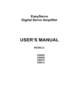
14 Servotronix
2.3 System Wiring - Pin Assignments
Figure 2-3. Pin Assignments
/