American Standard 3573.048WC.222 Installation guide
- Type
- Installation guide

754532-100 Rev. 3 3/19
1
THANK YOU...
for selecting an American Standard bath. Your new bath is shipped to you after careful inspection. The whirlpool
and air bath versions are completely assembled with pump/blower and system piping. All you need to finish the
installation are your selected fittings and electrical connections.
To ensure maximum performance and pleasure from this product, please follow the instructions and cautions.
For questions or service issues, please call Technical Support 1-(800)-442-1902.
Please do not contact or return product to the store.
MODEL 2742
MODEL 2748
MODEL 2806
MODEL 2903
MODEL 2932
MODEL 2934
MODEL 2938
MODEL 2940
MODEL 3571
MODEL 3572
MODEL 3573
MODEL 3574
MODEL 3575
MODEL 3581
INSTALLATION AND
OPERATION MANUAL
BATHTUBS, WHIRLPOOLS, AIR BATHS
AND COMBINATION TUBS WITH
OPTIONAL CHROMATHERAPY
© AS America, Inc. 2019
All product names listed herein are trademarks of AS America, Inc. unless otherwise noted.

2
754532-100 Rev. 3 3/19
TABLE OF CONTENTS:
Safety Instructions Notice.................................................................Page 3
Installation, Framing and Post Installation
Clean-Up Instructions.......................................................................Page 4
Roughing-in References for Recess Type Installations.....................Page 5
Roughing-in References for Pier Type Installations...........................Page 6
Under Deck Mounting Instructions....................................................Page 6
Roughing-in References for All Model Series...................................Page 7
Electrical Installation Instructions
.....................................................Page 18
Whirlpool Heater Operation
......
..........................................................Page 23
Remote Air Blower Location Option..................................................Page 24
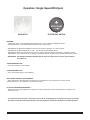
Operation: Single Speed Whirlpool...................................................Page 26
Operation: EcoSilent Whirlpool with Lights.......................................Page 27
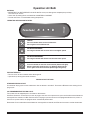
Operation: Air Bath............................................................................Page 28
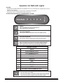
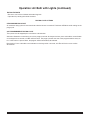
Operation: Air Bath with Lights..........................................................Page 29
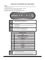
Operation: Combination Tub with Lights...........................................Page 31
Cleaning and Maintenence...............................................................Page 33
Warranty
......................................
.....................................................Page 34

754532-100 Rev. 3 3/19
3
IMPORTANT SAFETY
INSTRUCTIONS
READ AND FOLLOW ALL INSTRUCTIONS!
!
!
!
!
!
!
WARNING:
Risk of personal injury.
Do not permit children to use this bathtub without adult supervision. Never drop
or insert any object into any opening. Do not operate this unit without the guard over the suction fitting.
WARNING:
Risk of electric shock.
Do not permit electrical appliances near any bathtub when bathtub contains water.
WARNING:
Risk of hyperthermia and possible drowning.
People using medications and/or having adverse
medical history should consult a physician before using this product.
WARNING: Risk of personal injury. Do not overfill bathtub before entering. Entering tub when filled more than 2/3 can
cause overflow and slippery conditions. Exercise caution when entering and exiting.
WARNING:
No Food or Alcoholic Beverages.
Use of your bathtub immediately after meals is not recommended.
Avoid alcohol consumption before or during bathing. Alcoholic beverages can cause drowsiness or hyperthermia resulting in
loss of consciousness or even drowning.
WARNING:
Pregnancy.
If you are or think you may be pregnant, consult your physician before using the bathtub.
Use this unit only for its intended use as described in this manual.
Do not use any attachments not recommended by American Standard.
The unit must be connected only to a supply circuit that is properly protected by a ground-fault circuit-interrupter (GFCI).
Such a GFCI should be provided by the installer and should be tested on a routine basis. To test the GFCI, push the test
button. The GFCI should interrupt power. Push the reset button. Power should be restored. If the GFCI fails to operate in this
manner, the GFCI is defective. If the GFCI interrupts power to the bathtub without the test button being pushed, a ground
current is flowing, indicating the possibility of an electric shock. Do not use this air bath. Disconnect the air bath and have
the problem corrected by a licensed electrician before using.
SAVE THESE INSTRUCTIONS

4
754532-100 Rev. 3 3/19
Each bath arrives ready for installation, completely equipped with the pump/blower electronics
and plumbing necessary for operation. However, a drain/overflow kit is required for each bath
and it is not included.
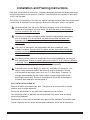
The variety of installations for this bath may require framing procedures other than those shown.
Locate studs as required. Ensure roughing-in dimensions are proper, plumb, and square.
Installation and Framing Instructions
Remove the bath from the carton. Retain the shipping carton until satisfactory
inspection of the product has been made. Do not lift the bath by the plumbing at
any time; handle by the shell only.
All bath units are factory tested for proper operation and watertight connections
prior to shipping. Prior to installation, the bath must be filled with water and
operated to check for leaks that may have resulted from shipping damage or
mishandling.
The sumps of these baths are supported by feet and no additional sump
support is required. Once the bath is in place, the feet should be shimmed and
secured accordingly so that the rim of the bath contacts the stringer or pier but
supports no weight.
Provisions must be made in all installations for an access opening for servicing the
bath pump/blower. Unless an access opening of at least 12" x 24" (305mm x 610mm)
is provided, warranty service will not be performed. It is strongly recommended that an
additional opening be provided for access to drain components.
Each bath has a nominal length (L), width (W), and Height (H) along with a rim
height. Unless otherwise noted in the following rough-in references, assume
that the nominal tolerances are as much as +/-1/4 inch (6mm). Therefore, it is
strongly recommended that the installer build the surrounding structure after
receiving the actual bath. Structural measurements should be verified against
the actual bath received to ensure proper fit.
!
!
!
!
!
POST INSTALLATION CLEAN-UP
Remove all construction debris from bath. Tile grout can be removed with a wooden
popsicle stick or tongue depressor.
Do not use wire brushes or any other metal implement on bath surface.
Post installation clean-up generally can be completed using warm water and liquid
dishwashing detergent.
Stubborn dirt or stains may be removed using granular Spic and Span
®
mixed with water.
Painter's naphtha can be used to remove excess adhesives and/or wet oil-base paint.

754532-100 Rev. 3 3/19
5
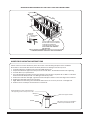
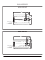
ROUGH-IN REFERENCES FOR RECESS TYPE INSTALLATIONS
TILE
TILE
BEAD
STRIP
LEVELING STRINGER
1" x 4" (25mm x 102mm) not for support
BATH
ADHESIVE
SEALANT
WALLBOARD
NOTE: Tile bead kit not included and must
be purchased separately.
SECURE THE BATH TO THE STUDS AS SHOWN
FOR WOOD OR STEEL STUD CONSTRUCTION.
TYPICAL TILE FLANGE INSTALLATION
TYPICAL TILE BEAD INSTALLATION
STUD
WATERPROOF DRYWALL
OR CEMENT BOARD
WATERPROOF DRYWALL
OR CEMENT BOARD
TILE
SEALANT
TUB
ROOFING NAIL
1" x 3" (25 x 76mm) WOOD
STRINGER FULL LENGTH
1" x 3" (25 x 76mm) WOOD
STRINGER FULL LENGTH
STEEL
STUD
WASHER
TILE
SEALANT
TUB
4" (102mm)
DRYWALL
SCREW
STEEL
STUDS
WOOD
STUDS
24"
(610 mm)
12"
(305 mm)
C
E
D
W
LEVELING
STRINGERS
ACCESS PANEL MUST BE LOCATED
ON THE SAME SIDE AS THE MOTOR.
ALLOW OPEN FRAMING ON
PUMP/MOTOR END FOR SERVICE.
UNLESS AN ACCESS OPENING OF AT LEAST 12" x 24" (305 x 610mm)
IS PROVIDED, WARRANTY SERVICE WILL NOT BE PERFORMED.
NOTE:
FRONT EDGE
OF BATH MUST
BE SUPPORTED
BY STUD WALL OR
AMERICAN STANDARD
APRON KIT
ACCESS PANELS NOT
REQUIRED FOR BATH TUBS

6
754532-100 Rev. 3 3/19
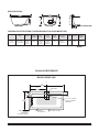
Please note that care must be taken to protect the surface of the tub during all aspects of the installation.
Do not drill or cut the bath deck with the tub directly beneath it as damage to the tub may result.
1. Install the tub per the installation instructions provided with the unit.
2. Prepare the bath deck support structure per the local codes. Note - the bath deck must be self supporting.
3. Cut bath deck to your specifications.
4. Place the bath deck in position and trace the opening on the tub with a soft pencil. Do not drill or cut the bath
deck with the tub directly beneath it as damage to the tub may result.
5. Remove the bath deck and apply a generous bead of waterproof sealant on the outer edge of the traced line.
6. Replace the bath deck and secure it into place.
7. Apply additional sealant along the tub and bath deck interface as necessary to ensure a watertight seal.
8. Remove excess sealant per the manufacturer's instructions.
Finished bath deck surface material must be
self-supporting and secured per local codes
Tub support structure per installation
instructions provided with the tub
Bath deck support material
Bathtub
Waterproof
Sealant
UNDER DECK MOUNTING INSTRUCTIONS
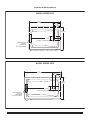
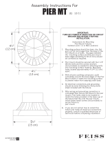
ROUGH-IN REFERENCES FOR PIER TYPE INSTALLATIONS
AS DESIRED
F
CUTOUT
AS DESIRED
G
CUTOUT
C
24"
(610 mm)
12"
(305 mm)
MOUNTING
SURFACE
WATERPROOF
SEALANT
BATH
ACCESS PANEL MUST BE LOCATED
ON THE SAME SIDE AS THE MOTOR.
ALLOW OPEN FRAMING ON
PUMP/MOTOR END FOR SERVICE.
ACCESS PANELS NOT REQUIRED
FOR BATH TUBS
UNLESS AN ACCESS OPENING OF AT LEAST 12" X 24" (305 X 610mm)
IS PROVIDED, WARRANTY SERVICE WILL NOT BE PERFORMED.

754532-100 Rev. 3 3/19
7
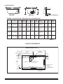
SPECIFICATIONS:
GENERAL SPECIFICATIONS FOR WHIRLPOOLS AND BATH TUBS
SIDE VIEW
DRAIN / OVERFLOW
END VIEW
L
H
W
C
A
B
J
A 16-1/4"
(413mm)
B 13-1/4"
(337mm)
A 14-1/2"
(368mm)
B 14-1/2"
(368mm)
A 17"
(432mm)
B 11"
(279mm)
A 17"
(432mm)
B 9-1/2"
(241mm)
4"
(102mm)
5-1/4"
(133mm)
5-1/2"
(140mm)
3"
(76mm)
C 20"
(508mm)
C 21"
(533mm)
C 19-1/2"
(495mm)
C 19-1/4"
(489mm)
70"
(1778mm)
x 40-1/4"
(1022mm)
58"
(1473mm)
x 40-1/8"
(1019mm)
Template
Provided
Template
Provided
71-11/16"
(1821mm)
x 40-1/4"
(1022mm)
59-11/16"
(1517mm)
x 40-1/8"
(1019mm)
As Desired
As Desired
L 71-1/2" (1816mm)
W 41-3/4" (1060mm)
H 22" (559mm)
L 59-1/2" (1511mm)
W 41-5/8" (1057mm)
H 23" (584mm)
L 72" (1829mm)
W 35-3/4" (908mm)
H 21-1/2" (546mm)
L 60" (1524mm)
W 42-1/4" (1073mm)
H 21-1/4" (540mm)
115 lb.
(52 kg.)
110 lb.
(50 kg.)
135 lb.
(61 kg.)
107 lb.
(49 kg.)
690 lb. (313 kg)/
33 lb./sq.ft.
(161 kg/sq.m)
611 lb. (277 kg)/
40 lb./sq.ft.
(196 kg/sq.m)
744 lb. (338 kg)/
41 lb./sq.ft.
(200 kg/sq.m)
640 lb. (291 kg)/
35 lb./sq.ft.
(171 kg/sq.m)
69 gal.
(261 l.)
60 gal.
(227 l.)
73 gal.
(276 l.)
64 gal.
(242 l.)
60 gal.
(227 l.)
55 gal.
(208 l.)
44 gal.
(166 l.)
53 gal.
(200 l.)
Description
Drain /
Overflow
Cut Out
Pier
G x F
Rough-In
Recess
E x D
Tub Edge to
Centerline
Overflow: J
Weight with
Water / Floor
Loading
Product
Weight
Gallon to
Overflow
Whirlpool
Operating
Volume
Height to
Underside of
Deck Edge: C
Dimensions
L-W-H
2742
Town Square
6' x 42"
2748
Town Square
5' x 42"
2806
Heritage Oval
6' x 36"
2903
Savona Oval
5' x 42"
TABLE 1
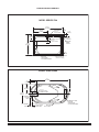
MODEL SERIES 2742
41-3/4"
(1060mm)
26-3/4"
(679mm)
C/L OF DRAIN OUTLET
71-1/2"
(1816mm)
35-3/4"
(908mm)
13-1/4"
(337mm)
4"
(102mm)
3"
(76mm)
FLOOR CUTOUT
5" X 15"
(127 X 381mm)
OUTLINE OF CUTOUT
70" X 40-1/4"
(1778 X 1022mm)
INTEGRAL
FITTING DECK
3" x 14"
(76 x 356mm)
3/4"
(19mm)
EDGE
OF FLOOR
CUTOUT
PROVIDE ACCESS
TO PUMP
SERVING ON
ALL INSTALLATIONS
ROUGH-IN REFERENCES

8
754532-100 Rev. 3 3/19
ROUGH-IN REFERENCES
MODEL SERIES 2748
59-1/2"
(1511mm)
INTEGRAL
FITTING DECK
3" X 14"
(76 X 356mm)
29-7/8"
(759mm)
41-5/8"
(1057mm)
OUTLINE OF CUTOUT
58-1/4" X 40-1/4"
(1480 X 1022mm)
C/L OF
DRAIN
OUTLET
FLOOR CUTOUT
5" X 12"
(127 X 305mm)
3/4"
(19mm)
14-1/2"
(368mm)
5-1/4"
(133mm)
3"
(76mm)
EDGE OF
FLOOR
CUTOUT
PROVIDE ACCESS
TO PUMP
SERVING ON
ALL INSTALLATIONS
INTEGRAL
FITTING
DECK
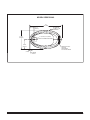
72"
(1829mm)
9" x 13"
(229 x 330mm)
FLOOR CUTOUT
11"
(279mm)
35-3/4"
(908mm)
18"
(457mm)
5-1/2"
(140mm)
C/L OF DRAIN
OVERFLOW
OUTLINE
OF CUTOUT
MODEL SERIES 2806
PROVIDE ACCESS
TO PUMP
SERVING ON
ALL INSTALLATIONS

754532-100 Rev. 3 3/19
9
OUTLINE OF
CUTOUT - USE
TEMPLAT E
9-1/2"
(241mm)
42-1/4"
(1073mm)
21-1/8"
(537mm)
3"
(76mm)
60"
(1524mm)
C
L
OF DRAIN
OUTLET
12" (305mm) X 9"(229mm)
CUTOUT IN FLOOR FOR DRAIN
ROUGH-IN REFERENCES
MODEL SERIES 2903
PROVIDE ACCESS
TO PUMP
SERVING ON
ALL INSTALLATIONS

10
754532-100 Rev. 3 3/19
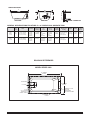
SPECIFICATIONS:
GENERAL SPECIFICATIONS FOR STUDIO 5' x 32" WHIRLPOOLS AND BATH TUBS
SIDE VIEW
DRAIN / OVERFLOW
END VIEW
L
H
W
C
A
B
J
A 17-3/4"
(451mm)
B 10-3/4"
(273mm)
A 17-3/4"
(451mm)
B 10-7/8"
(276mm)
C 21-7/8"
(556mm)
C 20-1/2"
(521mm)
58"
(1473mm)
x 30"
(762mm)
58-1/4"
(1480mm)
x 30-1/4"
(768mm)
59-11/16"
(1516mm)
x 30"
(762mm)
59-15/16"
(1522mm)
x 30-1/4"
(768mm)
3-1/4"
(83mm)
3-1/4"
(83mm)
L 59-1/2" (1511mm)
W 31-1/2" (800mm)
H 22-1/2" (572mm)
L 59-3/4" (1518mm)
W 31-3/4" (806mm)
H 22-1/2" (572mm)
90 lb.
(198 kg.)
90 lb.
(198 kg.)
581 lb. (264 kg)/
44 lb./sq.ft.
(213 kg/sq.m)
581 lb. (264 kg)/
44 lb./sq.ft.
(213 kg/sq.m)
59 gal.
(224 l.)
59 gal.
(224 l.)
54 gal.
(205 l.)
54 gal.
(205 l.)
Description
Drain /
Overflow
Cut Out
Pier
G x F
Rough-In
Recess
E x D
Tub Edge to
Centerline
Overflow: J
Zero
(5/8")
2"
Deck
Trim
Option
Weight with
Water / Floor
Loading
Product
Weight
Gallon to
Overflow
Whirlpool
Operating
Volume
Height to
Underside of
Deck Edge: C
Dimensions
L-W-H
2932
Studio
5' x 32"
2932
Studio
5' x 32"
TABLE 2
ROUGH-IN REFERENCES
MODEL SERIES 2932
60" NOMINAL
(1524mm)
32" NOMINAL
(813mm)
C/L DRAIN
OUTLINE OF
CUTOUT
9" x 15"
(229 x 305mm)
DRAIN ASS’Y
FLOOR CUTOUT
OVERFLOW
PROVIDE ACCESS
TO PUMP
SERVING ON
ALL INSTALLATIONS

754532-100 Rev. 3 3/19
11
SPECIFICATIONS:
GENERAL SPECIFICATIONS FOR STUDIO 5' x 36" WHIRLPOOLS AND BATH TUBS
SIDE VIEW
DRAIN / OVERFLOW
END VIEW
L
H
W
C
A
B
J
A 17-3/4"
(451mm)
B 10-3/4"
(273mm)
A 17-3/4"
(451mm)
B 10-7/8"
(276mm)
C 21-7/8"
(556mm)
C 20-1/2"
(521mm)
58"
(1473mm)
x 34"
(864mm)
58-1/4"
(1480mm)
x 34-1/4"
(870mm)
59-11/16"
(1516mm)
x 34"
(864mm)
59-15/16"
(1522mm)
x 34-1/4"
(870mm)
L 59-1/2" (1511mm)
W 35-1/2" (902mm)
H 22-1/2" (572mm)
L 59-3/4" (1518mm)
W 35-3/4" (908mm)
H 22-1/2" (572mm)
95 lb.
(209 kg.)
95 lb.
(209 kg.)
686 lb. (311 kg)/
46 lb./sq.ft.
(223 kg/sq.m)
686 lb. (311 kg)/
46 lb./sq.ft.
(223 kg/sq.m)
71 gal.
(269 l.)
71 gal.
(269 l.)
64 gal.
(243 l.)
64 gal.
(243 l.)
Description
Drain /
Overflow
Cut Out
Pier
G x F
Rough-In
Recess
E x D
Tub Edge to
Centerline
Overflow: J
Zero
(5/8")
2"
Deck
Trim
Option
Weight with
Water / Floor
Loading
Product
Weight
Gallon to
Overflow
Whirlpool
Operating
Volume
Height to
Underside of
Deck Edge: C
Dimensions
L-W-H
2934
Studio
5' x 36"
2934
Studio
5' x 36"
TABLE 3
ROUGH-IN REFERENCES
MODEL SERIES 2934
9" x 15"
(229 x 305mm)
DRAIN ASS’Y
FLOOR CUTOUT
60" NOMINAL
(1524mm)
36" NOMINAL
(914mm)
C/L DRAIN
OVERFLOW
OUTLINE OF
CUTOUT
PROVIDE ACCESS
TO PUMP
SERVING ON
ALL INSTALLATIONS
3-1/4"
(83mm)
3-1/4"
(83mm)

12
754532-100 Rev. 3 3/19
SPECIFICATIONS:
GENERAL SPECIFICATIONS FOR STUDIO 5-1/2' x 36" WHIRLPOOLS AND BATH TUBS
SIDE VIEW
DRAIN / OVERFLOW
END VIEW
L
H
W
C
A
B
J
A 17-3/4"
(451mm)
B 10-3/4"
(273mm)
A 17-3/4"
(451mm)
B 10-7/8"
(276mm)
C 21-7/8"
(556mm)
C 20-1/2"
(521mm)
64"
(1626mm)
x 34"
(864mm)
64-1/4"
(1632mm)
x 34-1/4"
(870mm)
65-11/16"
(1668mm)
x 34"
(864mm)
65-15/16"
(1675mm)
x 34-1/4"
(870mm)
L 65-1/2" (1664mm)
W 35-1/2" (902mm)
H 22-1/2" (572mm)
L 65-3/4" (1670mm)
W 35-3/4" (908mm)
H 22-1/2" (572mm)
100 lb.
(220 kg.)
100 lb.
(220 kg.)
766 lb. (348 kg)/
46 lb./sq.ft.
(227 kg/sq.m)
766 lb. (348 kg)/
46 lb./sq.ft.
(227 kg/sq.m)
80 gal.
(303 l.)
80 gal.
(303 l.)
73 gal.
(277 l.)
73 gal.
(277 l.)
Description
Drain /
Overflow
Cut Out
Pier
G x F
Rough-In
Recess
E x D
Tub Edge to
Centerline
Overflow: J
Zero
(5/8")
2"
Deck
Trim
Option
Weight with
Water / Floor
Loading
Product
Weight
Gallon to
Overflow
Whirlpool
Operating
Volume
Height to
Underside of
Deck Edge: C
Dimensions
L-W-H
2938
Studio
5-1/2' x 36"
2938
Studio
5-1/2' x 36"
TABLE 4
ROUGH-IN REFERENCES
MODEL SERIES 2938
9" x 15"
(229 x 305mm)
DRAIN ASS’Y
FLOOR CUTOUT
66" NOMINAL
(1676mm)
36" NOMINAL
(914mm)
C/L DRAIN
OVERFLOW
OUTLINE OF
CUTOUT
PROVIDE ACCESS
TO PUMP
SERVING ON
ALL INSTALLATIONS
3-1/4"
(83mm)
3-1/4"
(83mm)

754532-100 Rev. 3 3/19
13
SPECIFICATIONS:
GENERAL SPECIFICATIONS FOR STUDIO 6' x 36" WHIRLPOOLS AND BATH TUBS
SIDE VIEW
DRAIN / OVERFLOW
END VIEW
L
H
W
C
A
B
J
A 17-3/4"
(451mm)
B 10-3/4"
(273mm)
A 17-3/4"
(451mm)
B 10-7/8"
(276mm)
C 21-7/8"
(556mm)
C 20-1/2"
(521mm)
70"
(1778mm)
x 34"
(864mm)
70-1/4"
(1784mm)
x 34-1/4"
(870mm)
71-11/16"
(1821mm)
x 34"
(864mm)
71-15/16"
(1827mm)
x 34-1/4"
(870mm)
L 71-1/2" (1816mm)
W 35-1/2" (902mm)
H 22-1/2" (572mm)
L 71-3/4" (1822mm)
W 35-3/4" (908mm)
H 22-1/2" (572mm)
105 lb.
(231 kg.)
105 lb.
(231 kg.)
846 lb. (384 kg)/
47 lb./sq.ft.
(230 kg/sq.m)
846 lb. (384 kg)/
47 lb./sq.ft.
(230 kg/sq.m)
89 gal.
(337 l.)
89 gal.
(337 l.)
81 gal.
(307 l.)
81 gal.
(307 l.)
Description
Drain /
Overflow
Cut Out
Pier
G x F
Rough-In
Recess
E x D
Tub Edge to
Centerline
Overflow: J
Zero
(5/8")
2"
Deck
Trim
Option
Weight with
Water / Floor
Loading
Product
Weight
Gallon to
Overflow
Whirlpool
Operating
Volume
Height to
Underside of
Deck Edge: C
Dimensions
L-W-H
2940
Studio
6' x 36"
2940
Studio
6' x 36"
TABLE 5
ROUGH-IN REFERENCES
MODEL SERIES 2940
72" NOMINAL
(1829mm)
36" NOMINAL
(914mm)
C/L DRAIN
OUTLINE OF
CUTOUT
9" x 15"
(229 x 305mm)
DRAIN ASS’Y
FLOOR CUTOUT
OVERFLOW
PROVIDE ACCESS
TO PUMP
SERVING ON
ALL INSTALLATIONS
3-1/4"
(83mm)
3-1/4"
(83mm)

14
754532-100 Rev. 3 3/19
SPECIFICATIONS:
GENERAL SPECIFICATIONS FOR GREEN TEA WHIRLPOOLS AND BATH TUBS
SIDE VIEW
DRAIN / OVERFLOW
END VIEW
L
H
W
C
A
B
J
A 16"
(406mm)
B 11-1/2"
(349mm)
A 16"
(406mm)
B 11-1/2"
(349mm)
A 16"
(406mm)
B 11-1/2"
(349mm)
A 16"
(406mm)
B 11-1/2"
(349mm)
A 16"
(40mm)
B 11-1/2"
(349mm)
3-1/2"
(89mm)
3-3/4"
(95mm)
3-1/2"
(89mm)
3-1/8"
(79mm)
3-1/2"
(89mm)
C 19"
(483mm)
C 19"
(483mm)
C 19"
(483mm)
C 19"
(483mm)
C 19"
(483mm)
58-1/2"
(1485mm)
x 34-1/2"
(876mm)
64-1/2"
(1638mm)
x 34-1/2"
(876mm)
70-1/2"
(1791mm)
x 34-1/2"
(876mm)
58-1/2"
(1485mm)
x 40-1/2"
(1029mm)
70-1/2"
(1791mm)
x 40-1/2"
(1029mm)
60-3/16"
(1529mm)
x 34-1/2"
(876mm)
66-3/16"
(1681mm)
x 34-1/2"
(876mm)
72-3/16"
(1834mm)
x 34-1/2"
(876mm)
60-3/16"
(1528mm)
x 40-1/2"
(1029mm)
72-3/16"
(1834mm)
x 40-1/2"
(1029mm)
L 60" (1524mm)
W 36" (914mm)
H 21" (533mm)
L 66" (1676mm)
W 36" (914mm)
H 21" (533mm)
L 72" (1829mm)
W 36" (914mm)
H 21" (533mm)
L 60" (1524mm)
W 42" (1067mm)
H 21" (533mm)
L 72" (1829mm)
W 42" (1067mm)
H 21" (533mm)
86 lb.
(39 kg.)
100 lb.
(45 kg.)
115 lb.
(52 kg.)
115 lb.
(52 kg.)
127 lb.
(57 kg.)
519 lb. (236 kg)/
35 lb./sq.ft.
(171 kg/sq.m)
592 lb. (269 kg)/
36 lb./sq.ft.
(176 kg/sq.m)
665 lb. (302 kg)/
37 lb./sq.ft.
(181 kg/sq.m)
656 lb. (298 kg)/
38 lb./sq.ft.
(186 kg/sq.m)
785 lb. (356 kg)/
37 lb./sq.ft.
(181 kg/sq.m)
52 gal.
(197 l.)
59 gal.
(223 l.)
66 gal.
(250 l.)
65 gal.
(246 l.)
79 gal.
(299 l.)
38 gal.
(144 l.)
44 gal.
(166 l.)
49 gal.
(185 l.)
47 gal.
(178 l.)
58 gal.
(219 l.)
Description
Drain /
Overflow
Cut Out
Pier
G x F
Rough-In
Recess
E x D
Tub Edge to
Centerline
Overflow: J
Weight with
Water / Floor
Loading
Product
Weight
Gallon to
Overflow
Whirlpool
Operating
Volume
Height to
Underside of
Deck Edge: C
Dimensions
L-W-H
3571
Green Tea
5' x 36"
3572
Green Tea
5-1/2' x 36"
3573
Green Tea
6' x 36"
3574
Green Tea
5' x 42"
3575
Green Tea
6' x 42"
TABLE 6
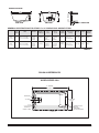
ROUGH-IN REFERENCES
MODEL SERIES 3571
60"
(1524mm)
36"
(914mm)
11-1/2"
(292mm)
OUTLINE OF CUTOUT 58.5" x 34.5" (1486 x 876mm)
14-3/4"
(375mm)
CUTOUT IN FLOOR FOR DRAIN
9"
(229mm)
C
L
PROVIDE ACCESS
TO PUMP
SERVING ON
ALL INSTALLATIONS

754532-100 Rev. 3 3/19
15
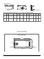
ROUGH-IN REFERENCES
MODEL SERIES 3572
66"
(1676mm)
11-1/2"
(292mm)
14-3/4"
(375mm)
36"
(914mm)
C
L
CUTOUT IN FLOOR FOR DRAIN
9"
(229mm)
OUTLINE OF CUTOUT 64.5" x 34.5" (1638 x 876mm)
PROVIDE ACCESS
TO PUMP
SERVING ON
ALL INSTALLATIONS
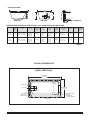
MODEL SERIES 3573
72"
(1829mm)
36"
(914mm)
11-1/2"
(292mm)
OUTLINE OF CUTOUT 70.5" x 34.5" (1780 x 876mm)
14-3/4"
(375mm)
9"
(229mm)
PROVIDE ACCESS
TO PUMP
SERVING ON
ALL INSTALLATIONS
C
L
CUTOUT IN FLOOR FOR DRAIN

16
754532-100 Rev. 3 3/19
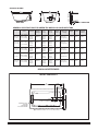
ROUGH-IN REFERENCES
MODEL SERIES 3574
60"
(1524mm)
42"
(1067mm)
11-1/2"
(292mm)
OUTLINE OF CUTOUT 58.5" x 40.5" (1486 x 1029mm)
14-3/4"
(375mm)
9"
(229mm)
PROVIDE ACCESS
TO PUMP
SERVING ON
ALL INSTALLATIONS
CUTOUT IN FLOOR FOR DRAIN
C
L
MODEL SERIES 3575
72"
(1829mm)
42"
(1067mm)
11-1/2"
(292mm)
OUTLINE OF CUTOUT 70.5" x 40.5" (1780 x 1029mm)
14-3/4"
(375mm)
C
L
9"
(229mm)
CUTOUT IN FLOOR FOR DRAIN
PROVIDE ACCESS
TO PUMP
SERVING ON
ALL INSTALLATIONS

754532-100 Rev. 3 3/19
17
GENERAL SPECIFICATIONS FOR SERIN WHIRLPOOLS AND BATH TUBS
A 16-3/4"
(425mm)
B 10-1/4"
(260mm)
C 20"
(508mm)
4-1/8"
(105mm)
58-1/2"
(1486mm)
x 30-1/2"
(775mm)
60-3/16"
(1529mm)
x 30-1/2"
(775mm)
L 60" (1524mm)
W 32" (813mm)
H 23" (584mm)
85 lb.
(37 kg.)
536 lb. (244 kg)/
40 lb./sq.ft.
(193 kg/sq.m)
54 gal.
(204 l.)
49 gal.
(186 l.)
3581
Serin
5' x 32"
TABLE 7
MODEL SERIES 3581
30"
(762mm)
60"
(1524mm)
9-3/4"
(248mm)
9" x 12" (227 x 305mm)
CUTOUT IN FLOOR
FOR DRAIN
OUTLINE OF CUTOUT
OVERFLOW
4-1/8"
(105mm)
INTEGRAL
FITTING DECK
32"
(813mm)
PROVIDE ACCESS
TO PUMP
SERVING ON
ALL INSTALLATIONS
ROUGH-IN REFERENCES
SPECIFICATIONS:
SIDE VIEW
DRAIN / OVERF
LOW
END VIEW
L
H
W
C
A
B
J
Description
Drain /
Overflow
Cut Out
Pier
G x F
Rough-In
Recess
E x D
Tub Edge to
Centerline
Overflow: J
Weight with
Water / Floor
Loading
Product
Weight
Gallon to
Overflow
Whirlpool
Operating
Volume
Height to
Underside of
Deck Edge: C
Dimensions
L-W-H
C
L

18
754532-100 Rev. 3 3/19
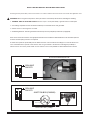
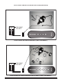
All wiring must be performed by a licensed electrician in accordance with the national electrical code and all other applicable codes.
WARNING: When using electrical products, basic precautions should always be observed, including the following:
1. DANGER: RISK OF ELECTRIC SHOCK! Connect only to a circuit protected by a ground-fault circuit interrupter.
2. Grounding is required. The unit should be installed by a licensed electrician and grounded.
3. Permit access for servicing motor as noted.
4. All building materials and wiring should be routed away from the pump body and heater (if equipped).
ELECTRICAL INSTALLATION INSTRUCTIONS
!
ELECTRICAL
FEED
GFCI
120V, 60HZ
15A GFCI
120V, 60HZ
15A GFCI
JUNCTION BOX (CANADA)
GFCI OUTLET (USA)
ELECTRICAL
FEED
AIR SWITCH ACTIVATED WHIRLPOOL PUMP
GFCI
Green/Copper
Black
White
Refer to the schematics below for the appropriate bath electrical installation. Dedicated15A circuits with GFCI (Ground
Fault Circuit Interrupter) protection are required.
At initial start-up with the power ON, push the GFCI test button. The reset button should pop out. Push this button in to
reset. If the GFCI fails to operate in this manner, there is a ground fault or malfunction, indicating the possibility of
electrical shock. Turn of the power and do not use until the source of the problem has been identifed and corrected.

754532-100 Rev. 3 3/19
19
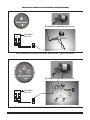
ELECTRICAL INSTALLATION INSTRUCTIONS (continued)
ELECTRONIC ACTIVATED AIR BATH (4 BUTTON PANEL)
120V, 60HZ
15A GFCI
ELECTRICAL
FEED
GFCI
ELECTRONIC ACTIVATED AIR BATH WITH LIGHTS (5 BUTTON PANEL)
120V, 60HZ
15A GFCI
ELECTRICAL
FEED
GFCI

20
754532-100 Rev. 3 3/19
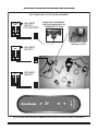
ELECTRICAL INSTALLATION INSTRUCTIONS (continued)
ELECTRONIC ACTIVATED ECOSILENT WHIRLPOOL (1 BUTTON PANEL)
120V, 60HZ
15A GFCI
ELECTRICAL
FEED
GFCI
ELECTRONIC ACTIVATED ECOSILENT WHIRLPOOL WITH LIGHTS (3 BUTTON PANEL)
ECOSILENT PUMP HAS P3JJ PLUG
ECOSILENT PUMP HAS P3JJ PLUG
120V, 60HZ
15A GFCI
ELECTRICAL
FEED
GFCI
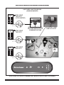
ELECTRICAL INSTALLATION INSTRUCTIONS (continued)
Page is loading ...
Page is loading ...
Page is loading ...
Page is loading ...
Page is loading ...
Page is loading ...
Page is loading ...
Page is loading ...
Page is loading ...
Page is loading ...
Page is loading ...
Page is loading ...
Page is loading ...
Page is loading ...
-
 1
1
-
 2
2
-
 3
3
-
 4
4
-
 5
5
-
 6
6
-
 7
7
-
 8
8
-
 9
9
-
 10
10
-
 11
11
-
 12
12
-
 13
13
-
 14
14
-
 15
15
-
 16
16
-
 17
17
-
 18
18
-
 19
19
-
 20
20
-
 21
21
-
 22
22
-
 23
23
-
 24
24
-
 25
25
-
 26
26
-
 27
27
-
 28
28
-
 29
29
-
 30
30
-
 31
31
-
 32
32
-
 33
33
-
 34
34


American Standard 3573.048WC.222 Installation guide
- Type
- Installation guide
Ask a question and I''ll find the answer in the document
Finding information in a document is now easier with AI
Related papers
-
Whirlpool 2940 User manual
-
American Standard 3575448WCK2.020 Installation guide
-
Whirlpool 2460028WC.222 User manual
-
-
-
-
-
-
-
Other documents
-
 T & S Brass & Bronze Works EW-8904 Datasheet
-
Aquatic Soco 6636 Owner's manual
-
Builders Edge 130110004030 Installation guide
-
 HOMZ 0417CB.08 User manual
-
Jacuzzi RIV7242WLR2XXB Specification
-
 Generation Lighting PIER MT-BRAL Operating instructions
-
Chipolino Set bath tub, baby bath bed and stand Hippo (88cm) Operating instructions
-
Kohler K-1969-GCW-0 Installation guide
-
CMP NEXXUS™ 4-BUTTON CONTROL Operating instructions
-


