KVH TrackPhone V7 Installation guide

Category
Networking
Type
Installation guide

This manual is also suitable for

Installation Guide
TracPhone
®
V7
32" (82 cm) Configuration
RF Cable Pigtails
1
Addendum
PLEASE READ!
Important Addendum to the Installation Guide
Two LMR-400-75 pigtail cables and rubber connector washers are
provided in the kitpack. Follow the steps below, while referring to
Figure 1, to connect these cables in-line between the antenna and the
customer’s RF cables, providing a reliable, weatherproof connection to
the antenna.
NOTE: Before you begin, be sure you have properly terminated, labeled, and
routed the customer’s “TX” and “RX” RF cables, as explained in the
Installation Guide.
Figure 1 LMR-400-75 Pigtail Connections
1. Clean and dry the antenna’s two RF connectors and the
RF cables’ connectors.
2. Heat shrink is supplied with each pigtail cable to protect
the connection between the customer’s RF cables and the
pigtail cables. Slide a heat shrink sleeve onto the end of
each pigtail cable (opposite the boot end) for later use.
Use of the supplied pigtail cables is mandatory for every new
installation. Do not connect the customer’s RF cables directly to the
antenna.
IMPORTANT!
Antenna Baseplate
Rubber Washer
Rubber Boot
Apply Silicone Grease
To Modem
A
A
Apply Silicone Grease
P
I
G
T
A
I
L
P
I
G
T
A
I
L
Feed-thru Adapter
Seal connection with
silicone sealant or
self-vulcanizing tape,
then apply heat-shrink
54-0841 Rev. A
RF Cable Pigtails
2
Addendum
3. Fill half of the inner body of the customer’s “TX” RF cable’s
connector with the supplied silicone grease (to prevent
moisture and corrosion).
4. Connect and SLOWLY hand-tighten the “TX” RF cable to
the feed-thru adapter of one of the supplied LMR-400-75
pigtail cables, allowing the grease to diffuse and settle into
the entire space within the connector.
5. Make sure the RF cable’s connector is tightened all the way
into the pigtail cable’s feed-thru adapter. Then tighten it
with a 7/16" torque wrench set to 20 in.-lbs.
6. Seal the RF cable-to-pigtail connection using silicone
sealant, self-vulcanizing tape, or equivalent. Then protect
the connection with the heat shrink (see step 2).
7. Place one of the supplied rubber connector washers over
the “MTx” jack on the bottom of the antenna, as shown in
Figure 1.
8. Fill half of the inner body of the “TX” pigtail cable’s male
connector with silicone grease.
9. Connect and SLOWLY hand-tighten the “TX” pigtail cable
to the antenna’s “MTx” jack, allowing the grease to diffuse
and settle into the entire space within the connector.
10. Make sure the “TX” pigtail cable’s connector is tightened
all the way into the antenna’s connector and the rubber
washer is compressed against the antenna’s base. Then
tighten the connector with a 7/16" torque wrench set to
20 in.-lbs.
11. Apply a thin layer of silicone grease to the jacket of the
“TX” pigtail cable, along the wider segment at the base of
the connector.
12. Slide the rubber boot up the cable until it covers the entire
connector and mates with the rubber washer. This will
protect the connection from the elements.
13. Wipe off any excess grease from the cable.
14. Repeat steps 3-13 to connect the “RX” RF cable and the
other pigtail cable to the “MRx” jack on the bottom of the
antenna.
The integrity and reliability of the RF cables and their connections
are critically important. Make certain that these cables are properly
terminated, sealed against seawater and corrosion, strain-relieved,
protected from abrasion, and free of stress. Refer to the Installation
Guide for details.
IMPORTANT!
AC Power and Grounding Requirements
1
Addendum
PLEASE READ!
Important Addendum to the Installation Guide
The KVH antenna system is AC powered, just like the other onboard
equipment to which it connects. Therefore, installing the system
requires careful examination of the AC power and grounding onboard
the vessel.
Figure 1 AC Power Options
KVH Antenna System
KVH Antenna System
Ground
50-120 VAC
Shipboard
Two-Phase,
Split-Phase,
or Delta Power
50-120 VAC
Leakage Current
KVH Antenna System
Shipboard
3-Wire
Single-Phase
AC Power
Ground
Neutral
N
100-240 VAC
OR
OR
Ground
Neutral
N
100-240 VAC
Single-Phase
Power Input
Ground Fault
Monitor
(when required)
Isolation Transformer
Ground
Ground
50-120 VAC
50-120 VAC
Shipboard
Two-Phase,
Split-Phase,
or Delta Power
54-0831 Rev. A
AC Power and Grounding Requirements
2
Addendum
AC Power Requirements
The KVH antenna system is designed to run on 3-wire single-phase
AC power (hot, neutral, and ground). Voltage between hot-neutral
and hot-ground should each measure between 100-240 VAC.
Many large ships use two-phase, split-phase, or delta power instead
(3 wires: hot, hot, and ground; no neutral). In this case, voltage
between hot-hot measures the proper voltage (100-240 VAC); while
hot-ground measures only half the voltage (50-120 VAC). Although
KVH antenna systems can operate on this type of power, the excess
voltage present on the second phase will cause a small amount of
current to leak onto ship's ground. This leakage current might be
unacceptable on some vessels. So be sure to check with the customer
or ship's electrician and get permission before you run the antenna
system on two-phase power. Also be sure to ground the system, as
explained on the next page.
If two-phase power is the only available power source onboard, and if
leakage current is unacceptable, KVH recommends that you install a
suitable isolation transformer to supply single-phase power to the
antenna system and run a ground wire from the transformer to ship's
ground. In addition, since ground fault protection devices cannot
detect faults behind a transformer, you will also need to install a
ground fault monitoring device between the isolation transformer and
the antenna system if ground fault protection is required on the vessel.
AC Power and Grounding Requirements
3
Addendum
Grounding Requirements
Proper grounding of the antenna system to ship's ground is critically
important, as it protects the equipment from lightning and
electrostatic discharges (ESD). Failure to ground the chassis of the
antenna's control unit risks damage to the antenna and electric shock.
In a standard installation with a connection to single-phase AC power,
the antenna system is normally connected to ship's ground through
the ground wire of the antenna control unit's power plug. As an
alternative, you may run a separate ground wire from the antenna
equipment's chassis to ship's ground, or mount the equipment within
a grounded equipment rack.
You are responsible for the quality and safety of the system’s
installation. Be sure that it meets these critical power and grounding
requirements.
WARNING
Failure to ground the antenna system properly to ship’s ground
will cause an unsafe floating ground condition, risking damage to
the antenna and electric shock, potentially resulting in DEATH.
In a floating ground condition, the difference between the
equipment’s chassis ground and the ship’s ground can measure
well over 100 volts, when it normally should not exceed 25 volts.
Therefore, always measure the difference in potential between
chassis ground and ship’s ground to make certain that there is no
dangerous floating ground condition, even if the ground pin of the
vessel’s AC power plug appears to be intact.
RF Cable Tool Kits
1
Addendum
PLEASE READ!
Important Addendum to Your Product Manual
KVH now includes a torque wrench and silicone grease with the
LMR-400-75 and LMR-600-75 RF cable termination tool kits. The
torque wrench is set to 20 in.-lbs, which KVH has found to be the ideal
torque for external RF cable connections.
The table below lists the updated part numbers for these tool kits, as
well as the associated RF cables.
Item KVH Part # Length
One RG-11 cable (for V3) 32-1087-50 50 ft (15 m)
One RG-11 cable (for V7) 32-0566-50 50 ft (15 m)
RG-11 tool kit 72-0493 N/A
One LMR-400-75 cable 32-0944-0100 100 ft (30 m)
LMR-400-75 tool kit 72-0374-75 N/A
One LMR-600-75 cable 32-0945-0150 150 ft (45 m)
LMR-600-75 tool kit 72-0375-75 N/A
You need to run two RF coax cables (transmit and receive) for
every TracPhone antenna installation, so be sure to order a
quantity of two cables for a new installation.
IMPORTANT!
54-0815 Rev. A
RF Cable Connectors
1
Addendum
PLEASE READ!
Important Addendum to Your Product Manual
A small packet of silicone grease is supplied in the kitpack. Apply this
grease to the inner body of all RF cable connectors that you connect to
the KVH antenna and any inline feed-thru adapters above deck. This
grease will help prevent moisture from seeping into or forming inside
the connector and protect the center conductor from corrosion.
Figure 1 Silicone Grease
Directions for Use
When connecting RF cables above deck to the KVH antenna, as well as
to any inline feed-thru adapters, follow the steps below to protect and
seal each connection:
1. Clean and dry the male connector on the RF cable and the
female connector on the antenna or feed-thru adapter.
2. Fill half of the inner body of the RF cable’s connector with
silicone grease. Connecting the cable in the next step will
displace the grease to fill the entire space within the connector.
3. Connect and SLOWLY hand-tighten the RF cable to the
antenna or feed-thru adapter, allowing the grease to diffuse
and settle into the entire connector body.
4. Make sure the RF cable’s connector is tightened all the way
into the female connector of the antenna or feed-thru
adapter. Then tighten the connection with a 7/16" torque
wrench set to
 in.-lbs.
5. Wipe off a
ny excess grease from the outside of the
connector.
6. Seal the connection with silicone sealant, self-vulcanizing
tape, or equivalent. If using self-vulcanizing tape, be sure to
wrap the tape CLOCKWISE around the connector (the
same direction in which you tightened the connector). Wrapping
the tape in the opposite direction will result in tension that
might loosen the connector over time.
The procedure is complete.
54-0779 Rev. A
This addendum applies to products with
antenna serial number 110601833 or later.
TracPhone V7 Installation Guide
1
KVH’s Complete mini-VSAT Broadband
sm
System
KVH, TracPhone, and the unique light-colored dome with dark contrasting baseplate are registered trademarks of KVH Industries, Inc.
All other trademarks are property of their respective companies. The information in this document is subject to change without notice.
No company shall be liable for errors contained herein. © 2008-2011 KVH Industries, Inc., All rights reserved. 54-0523 Rev. D
U.S. Patent Pending
These instructions explain how to install the TracPhone V7 mini-VSAT Broadband satellite
communications system. Instructions on how to use the system are provided in the User’s Guide.
Installation Steps
CAUTION - RF Radiation Hazard
Who Should Install the System?
To ensure a safe and effective installation, only a KVH-certified technician should install the
TracPhone system. KVH-certified technicians have the tools and electronics expertise necessary
to install the system. To find a technician near you, visit www.kvh.com/wheretogetservice.
Technical Support
1. Inspect Parts and Get Tools ................. 3
2. Plan the Antenna Installation.............. 4
3. Plan the Belowdecks Installation ........ 5
4. Prepare the Belowdecks Units............. 6
5. Prepare the Antenna Site...................... 9
6. Prepare the Antenna ........................... 10
7. Wire the Antenna ................................ 11
8. Mount the Antenna............................. 12
9. Remove the Restraints ........................ 13
10. Wire the Belowdecks Units.................14
11. Connect Power .....................................16
12. Configure the Computer(s) ................18
13. Turn On the System.............................21
14. Update the System Software..............22
15. Set Up RF Hazard Zones.....................23
16. Test the System.....................................24
17. Educate the Customer.........................26
The antenna transmits radio frequency (RF)
energy that is potentially harmful. Whenever the
system is powered on, make sure everyone stays
more than 36 feet (11 m) away from the antenna
within its 5-80° elevation range. No hazard exists
directly above the antenna and anywhere below
the antenna’s mounting plane.
North/South America, Australia:
Phone: +1 401 847-3327
Europe, Middle East, Asia, Africa:
Phone: +45 45 160 180
Antenna
Radiation
Hazard
Radiation
Hazard
3
6
f
t
(
11
m
)
36
f
t
(
1
1 m)
80
5
80
5
3
Before you begin, follow these steps to make sure
you have everything you need to complete the
installation.
a. Unpack the box and ensure it contains
everything shown in Figure 1 and on the
Kitpack Content Lists. Save the packaging for
future use.
b. Carefully examine all of the supplied parts to
ensure nothing was damaged in shipment.
c. Gather all of the following tools and
materials that you will need:
Flat-head and Phillips-head screwdrivers
Electric drill and 1/2" (13 mm) bit
2" (50 mm) hole saw
Wire cutters, wire strippers, and terminal
lug crimper
Socket wrenches and extension
11/16" open-end or box wrench, and
7/16" open-end wrench
Silicone sealant or self-vulcanizing tape
Light hammer and center punch
Adhesive tape and scriber or pencil
Two RF coax cables and F-connector
installation tools (see page 11)
Isolation transformer, if required (see
page 16)
•Windows
®
7, Vista
, or XP laptop with
the latest version of TPV7 Flash Update
Wizard installed (software available to
technicians on the KVH Partner Portal)
NOTE: KVH offers the optional KVH CommBox
for
connecting multiple communication systems to the
onboard local area network (LAN), providing least
cost routing, firewall, bandwidth management, web
caching, and optimization features (KVH part
#72-0470 (compact) or #72-0472 (rack-mount)).
Radome
Baseplate
Figure 1: TracPhone V7 System Components
Antenna
Control Unit
Modem
Ethernet Switch
Remote Service
& Support Module
Multimedia Terminal
Adapter (MTA)
Always lift the antenna by the baseplate and
never by the radome or any portion of the
internal antenna assembly (see Figure 1).
IMPORTANT!
Inspect Parts and Get Tools
1
4
Before you begin, consider the following antenna
installation guidelines:
Minimize blockage. The antenna requires a
clear view of the sky to transmit and receive
satellite signals (see Figure 2). The fewer
obstructions, the better the system will
perform.
Make sure the mounting surface is wide
enough to accommodate the antenna’s base
(see Figure 3). Also make sure it is flat, level,
strong enough to support the antenna’s
weight (100 lbs, 45 kg), and rigid enough to
withstand heavy vibration.
Select a location that is as close as possible to
the intersection of the vessel’s centerline and
midships.
Select a location that is well above any areas
accessible to passengers and crew to reduce
the risk of RF radiation exposure.
Avoid placing the antenna near any magnetic
compasses or other onboard antennas to
prevent potential interference.
Blocked!
Antenna
Mast
Vessel Platform
5° to 80°
Look Angle
Figure 2: Blockage from Obstruction
FWD
38.86"
(987 mm)
Ø35"
(Ø889 mm)
12"
(305 mm)
6"
(152 mm)
6"
(152 mm)
12"
(305 mm)
Hatch
17"
(432 mm)
4 x Ø.50"
(4 x Ø13 mm)
Figure 3: Antenna Dimensions
Side View
Bottom View
Do not mount the antenna at the same level as
the radar because the radar’s energy might
overload the antenna and damage its internal
components. Ideally, you should mount the
antenna 4 ft (1.2 m) above the radar, outside
the beam path of the radar.
IMPORTANT!
Plan the Antenna Installation
2
5
Before you begin, consider the following
installation guidelines for the belowdecks units.
Control Unit and Modem
Select a mounting location in a dry, well-
ventilated area belowdecks away from any
heat sources or salt spray.
Be sure the front panels will be easily
accessible to the user.
Leave enough room at the rear panel to
accommodate the connecting cables.
You have several options for mounting the
control unit and modem:
Option 1 - Inside the optional case
Option 2 - To a horizontal surface together
using two L-brackets
Option 3 - To a horizontal surface
separately using four L-brackets
NOTE: The control unit and modem are sized to
fit a standard 19" (482.6 mm) equipment rack.
To use the supplied data and power cables,
the control unit must be located within 100 ft
(30 m) of the antenna. However, you can
order 150 ft (45 m) cables if a longer cable run
is necessary (see Figure 18 on page 11).
Switch and MTA
To use the supplied Ethernet cables, select a
mounting location within 25 ft (7.5 m) of the
modem (maximum length = 200 ft (60 m)).
If you install a wireless access point (supplied
by customer), be sure the location provides
adequate WiFi reception. Do not install it in
an area surrounded by metal or near any
electrical devices that emit RF noise.
Remote Service & Support Module
To use the supplied serial data cable, select a
mounting location within 25 ft (7.5 m) of the
control unit (maximum length = 50 ft (15 m)).
Be sure the location provides adequate GPRS
cellular reception.
11.31"
(28.7 cm)
2.61"
(6.6 cm)
16.75"
(42.5 cm)
Figure 4: Control Unit or Modem Dimensions (Identical)
Figure 5: Case Dimensions
Figure 6: Dimensions of Ancillary Components
Component Dimensions (W x D x H)
Switch 6.7" x 3.9" x 1.1"
(17 cm x 9.9 cm x 2.8 cm)
MTA 4.6" x 5.12" x 1.18"
(11.7 cm x 13 cm x 3 cm)
Remote Service &
Support Module
5.12" x 3.54" x 1.5"
(13 cm x 9 cm x 3.8 cm)
Plan the Belowdecks Installation
3
6
If you plan to mount the control unit and modem
inside the optional 19" (482.6 mm) case, follow
these steps to assemble the case.
a. Remove the four M4 screws securing the rear
cover to the case. Discard the rear cover.
b. Attach the top cover to the case using four
M4 x 12 mm screws (see Figure 7). Attach the
bottom cover and the two mounting brackets
using four M4 x 16 mm screws.
c. Attach the four plastic feet to the bottom
cover (see Figure 7).
d. At the front of the case, insert eight cage nuts
into the following locations on the frame
(four on each side) (see Figure 7): #2, #5, #8,
and #11.
e. At the back of the case, insert four cage nuts
into the following locations on the frame (two
on each side): #1 and #3.
f. Remove the four #6-32 screws and washers
securing the two retaining straps to the rear
panel of the control unit. Do not remove the
bottom screws securing the straps to the modem.
g. Attach the strain-relief bracket to the
retaining straps and control unit using the
screws and washers you removed in Step f
(see Figure 8).
h. At the top 3U section of the case, insert the
control unit/modem assembly and secure the
front mounting brackets to the case using
four M6 screws and washers (see Figure 9).
i. At the bottom 3U section of the case, attach
the supplied blank panel using four M6
screws and washers (see Figure 9).
j. Secure the back of the control unit to the back
of the case using the two supplied “Z”
brackets. Attach the brackets to the case
frame using four M6 screws and washers.
Attach the brackets to the rear panel of the
control unit using four #6-32 screws and
washers (see Figure 9).
k. Once you have completed all system wiring,
mount the case to the vessel using fasteners
appropriate for the mounting surface.
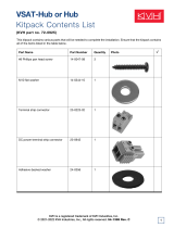
M4 x 16mm Screw (x4)
Mounting Bracket (x2)
Top Cover
Bottom Cover
M4 x 12mm Screw (x4)
Plastic Foot (x4)
1
2
3
4
5
6
7
8
9
10
11
12
Figure 7: Assembling the Case
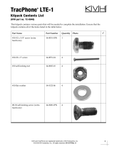
#6 Washer (x4)
#6-32 Screw (x4)
Strain-Relief
Bracket
Tie-Wrap
Holes (x12)
Retaining
Strap (x2)
Control Unit
Modem
Figure 8: Attaching the Strain-Relief Bracket
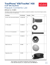
M6 Screw (x4)
Plastic Washer (x4)
#6 Washer (x4)
#6-32 Screw (x4)
“Z” Bracket (x2)
Cage Nut (x4)
Attach to Case
Attach to Control Unit
M6 Screw (x8)
Plastic Washer (x8)
Cage Nut (x8)
Blank Panel
Control Unit
and Modem
Case
Figure 9: Securing the Control Unit/Modem in the Case
Prepare the Belowdecks Units
4
Option 1 - Mounting in the Case
7
If you plan to mount the control unit and modem
together as an assembly, without using the
optional case or an equipment rack, follow these
steps to attach the strain-relief bracket and “L”
mounting brackets.
a. Remove the four #6-32 screws and washers
securing the two retaining straps to the rear
panel of the control unit. Do not remove the
bottom screws securing the straps to the modem.
b. Attach the strain-relief bracket to the
retaining straps and control unit using the
screws and washers you removed in Step a
(see Figure 10).
c. Attach two of the supplied “L” mounting
brackets to the sides of the control unit or
modem using four #6-32 screws and washers
(see Figure 11). You can attach the brackets to
either the top of the control unit or the bottom
of the modem, depending on your desired
mounting location.
d. Once you have completed all system wiring,
mount the modem/control unit assembly to
the vessel using fasteners appropriate for the
mounting surface.
Figure 10: Attaching the Strain-Relief Bracket
#6 Washer (x4)
#6-32 Screw (x4)
Strain-Relief
Bracket
Tie-Wrap
Holes (x12)
Retaining
Strap (x2)
Control Unit
Modem
#6 Washer (x4)
#6-32 Screw (x4)
Bracket (x2)
Control Unit
Modem
Ø.156" (Ø3.96 mm)
Mounting Hole (x4)
Figure 11: Attaching the Mounting Brackets
Prepare the Belowdecks Units
4
Option 2 - Mounting Units Together
8
If you plan to mount the control unit and modem
separately, follow these steps to detach the
control unit from the modem, attach the strain-
relief brackets, and attach the “L” mounting
brackets.
a. Remove the 28 #6-32 screws and washers
securing the two rack-mount brackets and
four metal retaining straps to the control unit
and modem (see Figure 12). Remove the
brackets and straps.
b. Attach a strain-relief bracket to the back of
the control unit using four of the screws and
washers you removed in Step a (see
Figure 13).
c. Attach a second strain-relief bracket to the
back of the modem using four of the screws
and washers you removed in Step a (see
Figure 14).
d. Attach two of the supplied “L” brackets to
the sides of the control unit using four #6-32
screws and washers (see Figure 11 on page 7).
You can attach the brackets at either the top
or bottom of the control unit, depending on
your desired mounting location.
e. Attach the two other supplied “L” brackets to
the sides of the modem using four #6-32
screws and washers (see Figure 11 on page 7).
You can attach the brackets at either the top
or bottom of the modem, depending on your
desired mounting location.
f. Once you have completed all system wiring,
mount the control unit and modem to the
vessel using fasteners appropriate for the
mounting surface.
#6-32 Screw (x28)
#6 Washer (x28)
Bracket (x2)
Strap (x4)
Contr
ol
Unit
M
o
dem
Figure 12: Detaching the Control Unit from the Modem
#6 Washer (x4)
#6-32 Screw (x4)
Strain-Relief
Bracket
Tie-wrap
Holes (x12)
Control Unit
Figure 13: Attaching the Bracket to the Control Unit
#6 Washer (x4)
#6-32 Screw (x4)
Strain-Relief
Bracket
Tie-wrap
Holes (x12)
Modem
Figure 14: Attaching the Bracket to the Modem
Prepare the Belowdecks Units
4
Option 3 - Mounting Units Separately
9
Once you have identified a suitable antenna
mounting site, according to the guidelines
provided in Step 2, follow these steps to drill the
mounting holes and cable access hole to prepare
the site for installation.
a. Unfold the antenna mounting template
(supplied in the Customer Welcome Kit) and
place it onto the mounting surface. Make sure
the “FWD” (forward) arrow points toward
the bow and is parallel to the vessel’s
centerline (see Figure 15).
NOTE: You don’t need to mount the antenna
exactly on the vessel’s centerline, but the
antenna’s forward arrow must be parallel to it.
b. Using a light hammer and center punch,
mark the locations for the four mounting
holes and cable access hole on the mounting
surface in the locations indicated on the
template.
c. Drill a 1/2" (13 mm) hole at the four
mounting hole locations you marked in
Step b. Later, you will insert four M10 bolts
from below to secure the antenna to the
mounting surface.
d. Cut out the 2" (50 mm) cable access hole in
the location you marked in Step b. Smooth
the edges of the hole to protect the cables.
Later, you will route the data, power, and RF
cables through this hole and into the vessel.
e. Clean and dry the antenna mounting surface.
f. Peel off the paper backing from the supplied
foam seal to expose the adhesive. Then press
the foam seal down firmly onto the mounting
surface, ensuring the hole in the foam seal
aligns with the cable access hole in the
mounting surface (see Figure 15).
NOTE: Apply the foam seal to the vessel
mounting surface, not to the antenna’s baseplate.
You will have difficulty connecting cables to the
antenna if the foam seal is attached to the
baseplate.
FWD
Foam Seal
Ø1/2" (Ø13 mm)
Mounting Hole (x4)
12"
(305 mm)
6"
(152 mm)
12"
(305 mm)
Ø2" (Ø50 mm)
Cable Access Hole
6"
(152 mm)
Baseplate Footprint
Ø17"
(Ø432 mm)
Figure 15: Antenna Mounting Holes Layout
Prepare the Antenna Site
5
10
Follow these steps to remove the service hatch
and radome. They must be removed before you
can wire and mount the antenna.
a. Remove the eleven M4 screws securing the
service hatch to the antenna’s baseplate (see
Figure 16). Set the hatch aside in a safe place.
b. Remove and save the two #10-32 Phillips
screws securing the radome to the baseplate.
(The six other radome screws are in the kitpack.
You will use these later when you reinstall the
radome.) Carefully lift the radome straight up
until clear of the antenna assembly and set it
aside in a safe place (see Figure 17).
TIP: If you keep the radome topside, secure it with
a lanyard to prevent it from falling overboard.
M4 Screw (x11)
Service Hatch
Figure 16: Baseplate Service Hatch
Baseplate
#10-32
Screw (x8)
Radome
Figure 17: Removing the Radome
Prepare the Antenna
6
11
Follow these steps to connect the antenna cables.
a. In addition to the data and power cables, you
will need to connect two 75 RF coax cables
from the antenna to the belowdecks
equipment. Use the guidelines in Figure 18 to
determine the type of RF cables required.
b. Label both ends of the two RF cables. Label
one cable “TX,” and label the other “RX.”
c. Route the data, power, and RF cables
belowdecks through the 2" (50 mm) cable
access hole. Keep 2 ft (60 cm) of each cable
outside the hole to allow enough slack to
connect the cables and maintain a service
loop inside the antenna.
d. Insert the other ends of the cables up through
the center hole in the bottom of the antenna’s
baseplate.
e. Connect the data cable to the “Data” jack on
the bottom of the antenna assembly (see
Figure 19). Hand-tighten until the connector
locks in place; do not use excessive force.
f. Connect the power cable to the “Power” jack
on the bottom of the antenna assembly.
Hand-tighten until locked in place.
g. Connect the RF cable labeled “TX” to the
“MTx” jack on the bottom of the antenna
assembly. Hand-tighten, then tighten with a
7/16" wrench for 1/4 turn to ensure a good
electrical connection.
h. Connect the RF cable labeled “RX” to the
“MRx” jack on the bottom of the antenna
assembly. Hand-tighten, then tighten with a
7/16" wrench for 1/4 turn.
i. Seal both RF cable connections with silicone
sealant, self-vulcanizing tape, or equivalent.
Figure 18: RF Cable Requirements*
* For alternate cable options, see the Application Notes
section of the KVH Partner Portal (technicians only).
15-50 ft (5-15 m) Cable Run
Cable: RG-11
Connector: SNS11AS
Installation Tools: CST596711 and L3011B
51-100 ft (16-30 m) Cable Run
Cable: LMR-400-75
Connector: EZ-400-FMH-75
Installation Tools: TK-400EZ-75
101-150 ft (31-45 m) Cable Run
Cable: LMR-600-75
Connector: EZ-600-FMH-75
Installation Tools: TK-600EZ
0.25" (6.35 mm)
0.5" (12.7 mm)
0.064" (1.63 mm) dia.
0.170" (4.32 mm)
0.344" (8.74 mm)
0.065" (1.65 mm) dia.
0.610" (15.49 mm)
0.250" (6.35 mm)
0.370" (9.40 mm)
0.108" (2.74 mm) dia.
0.870" (22.10 mm)
NOTE: Optional 150 ft (45 m) data and power cables:
Data cable KVH part #32-0921-0150
Power cable KVH part #32-0924-0150
NOTE: RG-11 connectors/tools are manufactured by
Thomas & Betts. LMR-400-75 and LMR-600-75 cables/
connectors/tools are manufactured by Times Microwave.
Terminate RF cables with the proper type “F”
connectors (see Figure 18). Instructions for
terminating LMR-400-75 cable are provided
in Appendix B on page 30.
IMPORTANT!
MRxMTx
Power
Data
Figure 19: Connectors on Bottom of Antenna Assembly
Wire the Antenna
7
12
Follow these steps to mount the antenna to the
mounting surface.
a. Place the antenna baseplate over the holes
drilled in the mounting surface.
b. Make sure the service hatch faces the stern of
the vessel. Also make sure the forward arrow
inside the baseplate points toward the bow
and is parallel to the vessel’s centerline (see
Figure 20).
c. Make sure the four holes in the baseplate line
up with the four holes in the mounting
surface.
d. At each of the four baseplate mounting holes,
place an M10 lock washer and flat washer on
an M10 bolt and insert the bolt into the hole
from below (see Figure 21).
e. Tighten all four bolts until the four rubber
feet on the baseplate are bottomed against the
mounting surface and the foam seal is fully
compressed. KVH recommends that you
tighten the bolts to between 12 and 16 ft-lbs
(16.2 and 21.7 N-m) of torque.
Figure 20: Forward Arrow in Antenna Baseplate
M10 x 50 mm Bolt (x4)
Foam Seal
M10 Flat Washer (x4)
M10 Lock Washer (x4)
10 mm max.
Mounting Surface
Antenna Base
Figure 21: Mounting the Antenna (Side View)
Mount the Antenna
8
13
Inside the antenna, several shipping restraints
prevent the antenna assembly from moving
during shipment. Follow these steps to remove
these shipping restraints.
a. Using an 11/16" wrench and a 9/16" socket
with 6" extension, remove the two 3/8" bolts,
washers, and lock nuts securing the azimuth
shipping restraints to the base of the antenna
assembly (see Figure 22). Remove the “L”
bracket restraints.
b. Place a 3/8" flat washer (supplied in the
kitpack) on the two 3/8" bolts that you
removed in Step a. Reinstall the bolts and
secure in place with the washers and lock
nuts you removed in Step a (see Figure 23).
These bolts secure the antenna assembly to
the internal mounting platform.
c. Using wire cutters, cut and remove the wire
shipping restraint securing the reflector to the
antenna frame (see Figure 24).
d. Cut and remove the tie-wrap securing the
antenna’s LNB to the back of the reflector (see
Figure 24).
e. Reinstall the radome onto the antenna. Secure
in place with the two #10-32 screws you
removed in Step 6b, along with the six #10-32
screws supplied in the kitpack (see Figure 17
on page 10).
f. Reattach the service hatch to the antenna’s
baseplate using the M4 screws you removed
in Step 6a (see Figure 16 on page 10).
g. Install a protective plastic cap (supplied in
the kitpack) over each radome screw.
3/8" Bolt (x2)
Lock Nut (x2)
Washer (x2)
Bracket (x2)
Figure 22: Removing the Shipping Restraint Brackets
3/8" Bolt (x2)
Lock Nut (x2)
Washer (x2)
Washer, Supplied
in Kitpack (x2)
Figure 23: Reinstalling the Mounting Bolts
IMPORTANT
Wire
Tie-wrap
IMPORTANT
REMOVE THIS SHIPPING
RESTRAINT BEFORE OPERATING
Figure 24: Removing the Wire and Tie-wrap Restraints
Remove the Restraints
9
  • Page 1 1
  • Page 2 2
  • Page 3 3
  • Page 4 4
  • Page 5 5
  • Page 6 6
  • Page 7 7
  • Page 8 8
  • Page 9 9
  • Page 10 10
  • Page 11 11
  • Page 12 12
  • Page 13 13
  • Page 14 14
  • Page 15 15
  • Page 16 16
  • Page 17 17
  • Page 18 18
  • Page 19 19
  • Page 20 20
  • Page 21 21
  • Page 22 22
  • Page 23 23
  • Page 24 24
  • Page 25 25
  • Page 26 26
  • Page 27 27
  • Page 28 28
  • Page 29 29
  • Page 30 30
  • Page 31 31
  • Page 32 32
  • Page 33 33
  • Page 34 34
  • Page 35 35
  • Page 36 36
  • Page 37 37
  • Page 38 38
  • Page 39 39
  • Page 40 40

KVH TrackPhone V7 Installation guide

Category
Networking
Type
Installation guide
This manual is also suitable for

Ask a question and I''ll find the answer in the document

Finding information in a document is now easier with AI