Page is loading ...

CHAPTER
1-1
Cisco Metro 1500 Series Hardware Installation Guide
78-10588-03
1
Product Overview
This chapter describes the Cisco Metro 1500 series metropolitan area network
(MAN) dense wavelength division multiplexing (DWDM) system, and includes
the following sections:
• Product Description, page 1-1
• Communication Channels, page 1-2
• Chassis, page 1-11
• System Modules, page 1-15
Product Description
The Cisco Metro 1500 series system is a high-performance, wavelength division
multiplexer that provides bidirectional data communication. It is designed for
communication over optical links in which different devices or applications are
communicating over multiple fibers. Using wavelength conversion, several
devices can communicate while being connected over one duplex fiber or two
single fibers.
The Cisco Metro 1500 series system expands the distance and application
capabilities of existing local area networks (LANs), metropolitan area networks
(MANs), and storage area networks (SANs). It is protocol-independent and can
support virtually any fiber-optic device.

Chapter 1 Product Overview
Communication Channels
1-2
Cisco Metro 1500 Series Hardware Installation Guide
78-10588-03
The Cisco Metro 1500 series operates using the International Telecommunication
Union (ITU) wavelength grid of 200-GHz channel spacing. It receives the signal
from the local device and converts it to the desired wavelength. Only single-mode
fibers (remote or trunk fibers) are used for multiplexed data transmission.
The Cisco Metro 1500 series system provides communication within a broad
range of data rates, up to 2.488 Gbps, and within a guaranteed optical budget. The
system is transparent to any data communication protocol except wavelength
channel modules (WCMs) with clock recovery. For more details on data rates,
optical budgets, and supported protocols, see Appendix A, “Specifications.”
The Cisco Metro 1500 series system also provides monitoring and service
functions such as loss of light and bit-rate control, as well as local and remote
loopback.
Communication Channels
DWDM technology allows different channels to be combined for transportation
over one fiber pair. A pair of multiplexer (MUX) and demultiplexer (DMX)
modules assemble the channels into four groups of up to eight channels. The band
splitter module (BSM) assembles and disassembles the four groups for the two
remote fibers.
The optional remote switch module (RSM) provides line protection to the system.
If the working line fails, the RSM routes the combined service automatically to a
backup line. If used, the RSM is installed only in the primary chassis.

1-3
Cisco Metro 1500 Series Hardware Installation Guide
78-10588-03
Chapter 1 Product Overview
Communication Channels
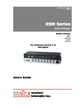
Figure 1-1 shows the multiplexer architecture.
Figure 1-1 Multiplexer Architecture
Extension chassis C
Extension chassis A
Extension chassis B
Primary chassis
Transmission
fiber lines
Receiving
fiber lines
MUX
BSM RSM
Extension chassis C
Extension chassis A
Extension chassis B
Primary chassis
DMX
CH25
CH32
CH17
CH24
CH9
CH16
CH1
CH8
CH25
CH32
CH17
CH24
CH9
CH16
CH1
CH8
39354

Chapter 1 Product Overview
Communication Channels
1-4
Cisco Metro 1500 Series Hardware Installation Guide
78-10588-03
Primary and Extension Chassis
The Cisco Metro 1500 series system has a modular structure so you can expand
the system while it is in use. Adding or removing channels does not affect the
other working channels. Figure 1-2 shows a typical Cisco Metro 1500 series
system configuration containing a primary chassis and three extension chassis.

1-5
Cisco Metro 1500 Series Hardware Installation Guide
78-10588-03
Chapter 1 Product Overview
Communication Channels
Figure 1-2 Typical Cisco Metro 1500 Series Configuration
DC Input Uplink 6x 5x 4x 3x 2x 1x
50317
FAIL
POWER
OK FAILOK
FAN
L/T
R/T
R/R
L/R
Loop
On/Err
L/T
R/T
R/R
L/R
L/T
R/T
R/R
L/R
Loop
On/Err
L/T
R/T
R/R
L/R
L/T
R/T
R/R
L/R
Loop
On/Err
L/T
R/T
R/R
L/R
L/T
R/T
R/R
L/R
Loop
On/Err
L/T
R/T
R/R
L/R
L/T
R/T
R/R
L/R
Loop
On/Err
L/T
R/T
R/R
L/R
L/T
R/T
R/R
L/R
Loop
On/Err
L/T
R/T
R/R
L/R
L/T
R/T
R/R
L/R
Loop
On/Err
L/T
R/T
R/R
L/R
L/T
R/T
R/R
L/R
Loop
On/Err
L/T
R/T
R/R
L/R
1-8(32) 1-8(32)
MUX DMX
7
8
M1
nc
7
8
5
6
3
4
1
2
D1
nc
7
8
5
6
3
4
1
2
on
Power
on
Power
I
0
METRO 1500 SERIES
Err
On
BUS 1
BUS 2
FAIL
POWER
OK FAILOK
FAN
L/T
R/T
R/R
L/R
Loop
On/Err
L/T
R/T
R/R
L/R
L/T
R/T
R/R
L/R
Loop
On/Err
L/T
R/T
R/R
L/R
L/T
R/T
R/R
L/R
Loop
On/Err
L/T
R/T
R/R
L/R
L/T
R/T
R/R
L/R
Loop
On/Err
L/T
R/T
R/R
L/R
L/T
R/T
R/R
L/R
Loop
On/Err
L/T
R/T
R/R
L/R
L/T
R/T
R/R
L/R
Loop
On/Err
L/T
R/T
R/R
L/R
L/T
R/T
R/R
L/R
Loop
On/Err
L/T
R/T
R/R
L/R
L/T
R/T
R/R
L/R
Loop
On/Err
L/T
R/T
R/R
L/R
1-8(32) 1-8(32)
MUX DMX
7
8
M1
nc
7
8
5
6
3
4
1
2
D1
nc
7
8
5
6
3
4
1
2
on
Power
on
Power
I
0
METRO 1500 SERIES
Power
Error
Err.Int.BUS
Err.Ext.BUS
Receive
Link
BUS 1
BUS 2
Serial
Net
FAIL
POWER
OK FAILOK
FAN
L/T
R/T
R/R
L/R
Loop
On/Err
L/T
R/T
R/R
L/R
L/T
R/T
R/R
L/R
Loop
On/Err
L/T
R/T
R/R
L/R
L/T
R/T
R/R
L/R
Loop
On/Err
L/T
R/T
R/R
L/R
L/T
R/T
R/R
L/R
Loop
On/Err
L/T
R/T
R/R
L/R
L/T
R/T
R/R
L/R
Loop
On/Err
L/T
R/T
R/R
L/R
L/T
R/T
R/R
L/R
Loop
On/Err
L/T
R/T
R/R
L/R
L/T
R/T
R/R
L/R
Loop
On/Err
L/T
R/T
R/R
L/R
L/T
R/T
R/R
L/R
Loop
On/Err
L/T
R/T
R/R
L/R
1-8(32) 1-8(32)
MUX DMX
7
8
M1
nc
7
8
5
6
3
4
1
2
D1
nc
7
8
5
6
3
4
1
2
on
Power
on
Power
I
0
METRO 1500 SERIES
Err
On
BUS 1
BUS 2
FAIL
POWER
OK FAILOK
FAN
L/T
R/T
R/R
L/R
Loop
On/Err
L/T
R/T
R/R
L/R
L/T
R/T
R/R
L/R
Loop
On/Err
L/T
R/T
R/R
L/R
L/T
R/T
R/R
L/R
Loop
On/Err
L/T
R/T
R/R
L/R
L/T
R/T
R/R
L/R
Loop
On/Err
L/T
R/T
R/R
L/R
L/T
R/T
R/R
L/R
Loop
On/Err
L/T
R/T
R/R
L/R
L/T
R/T
R/R
L/R
Loop
On/Err
L/T
R/T
R/R
L/R
L/T
R/T
R/R
L/R
Loop
On/Err
L/T
R/T
R/R
L/R
L/T
R/T
R/R
L/R
Loop
On/Err
L/T
R/T
R/R
L/R
1-8(32) 1-8(32)
MUX DMX
7
8
M1
nc
7
8
5
6
3
4
1
2
D1
nc
7
8
5
6
3
4
1
2
on
Power
on
Power
I
0
METRO 1500 SERIES
Power
Error
Err.Int.BUS
Err.Ext.BUS
Receive
Link
BUS 1
BUS 2
Serial
Net
DEMI
DEMI
NEMI slave
External bus cable
NEMI master
Primary chassis:
WCM 1-8
Chassis A:
WCM 9-16
Chassis B:
WCM 17-24
Chassis C:
WCM 25-32
Ethernet hub
Ethernet cables

Chapter 1 Product Overview
Communication Channels
1-6
Cisco Metro 1500 Series Hardware Installation Guide
78-10588-03
Expansion Modules
The Cisco Metro 1500 series system requires two identical WCMs to complete a
full communications link, one at each end of the link. Each system unit includes
a primary chassis (see Figure 1-3) that holds up to eight WCMs. The WCMs
transport up to eight independent channels.
Figure 1-3 Primary Chassis
The Cisco Metro 1500 series system can be expanded by adding more WCMs.
Adding extension chassis A, B, and C (Figure 1-4 to Figure 1-6) at both ends of
the communications link upgrades the system to transport a total of 32
independent channels. A network element management interface (NEMI) can
control up to two chassis and up to four NEMIs can be combined through an
Ethernet hub or switch to appear as a single system as seen by a Network
Management System (NMS). We recommend that you initially install the primary
chassis and extension chassis A, which holds the BSM, to avoid service
interruption while upgrading the unit to more than eight channels. The primary
chassis and the extension chassis are each equipped with two fully redundant
load-sharing, hot-swappable power supply modules (PSMs), as shown in
Figure 1-3 to Figure 1-6.
WCM
RSM
MUX
Power 1
Power 2
NEMI
DMX
FAIL
POWER
OK FAILOK
FAN
L/T
R/T
R/R
L/R
Loop
On/Err
L/T
R/T
R/R
L/R
L/T
R/T
R/R
L/R
Loop
On/Err
L/T
R/T
R/R
L/R
L/T
R/T
R/R
L/R
Loop
On/Err
L/T
R/T
R/R
L/R
L/T
R/T
R/R
L/R
Loop
On/Err
L/T
R/T
R/R
L/R
L/T
R/T
R/R
L/R
Loop
On/Err
L/T
R/T
R/R
L/R
L/T
R/T
R/R
L/R
Loop
On/Err
L/T
R/T
R/R
L/R
L/T
R/T
R/R
L/R
Loop
On/Err
L/T
R/T
R/R
L/R
L/T
R/T
R/R
L/R
Loop
On/Err
L/T
R/T
R/R
L/R
Auto
L B
k
L A
k
L
k
A
On
B/T
B/R
M
D
A/T
A/R
B
Power
Error
Err.Int.BUS
Err.Ext.BUS
Receive
Link
BUS 1
BUS 2
Serial
Net
1-8(32) 1-8(32)
MUX DMX
7
8
M1
nc
7
8
5
6
3
4
1
2
D1
nc
7
8
5
6
3
4
1
2
on
Power
on
Power
I
0
METRO 1500 SERIES
39943

1-7
Cisco Metro 1500 Series Hardware Installation Guide
78-10588-03
Chapter 1 Product Overview
Communication Channels
Figure 1-4 Extension Chassis A
Figure 1-5 Extension Chassis B
WCM
DEMI
BSM
MUX
DMX
Power 1 Power 2
POWER FAN
L/T
R/T
R/R
L/R
Loop
On/Err
L/T
R/T
R/R
L/R
L/T
R/T
R/R
L/R
Loop
On/Err
L/T
R/T
R/R
L/R
L/T
R/T
R/R
L/R
Loop
On/Err
L/T
R/T
R/R
L/R
L/T
R/T
R/R
L/R
Loop
On/Err
L/T
R/T
R/R
L/R
L/T
R/T
R/R
L/R
Loop
On/Err
L/T
R/T
R/R
L/R
L/T
R/T
R/R
L/R
Loop
On/Err
L/T
R/T
R/R
L/R
L/T
R/T
R/R
L/R
Loop
On/Err
L/T
R/T
R/R
L/R
L/T
R/T
R/R
L/R
Loop
On/Err
L/T
R/T
R/R
L/R
1-8(32) 1-8(32)
MUX DMX
7
8
M1
nc
7
8
5
6
3
4
1
2
D1
nc
7
8
5
6
3
4
1
2
on
Power
on
Power
I
0
METRO 1500 SERIES
Err
On
BUS 1
BUS 2
BSM
M1
D1
M2
D2
M3 D3
M4 D4
MD
39340
FAIL
POWER
OK FAILOK
FAN
L/T
R/T
R/R
L/R
Loop
On/Err
L/T
R/T
R/R
L/R
L/T
R/T
R/R
L/R
Loop
On/Err
L/T
R/T
R/R
L/R
L/T
R/T
R/R
L/R
Loop
On/Err
L/T
R/T
R/R
L/R
L/T
R/T
R/R
L/R
Loop
On/Err
L/T
R/T
R/R
L/R
L/T
R/T
R/R
L/R
Loop
On/Err
L/T
R/T
R/R
L/R
L/T
R/T
R/R
L/R
Loop
On/Err
L/T
R/T
R/R
L/R
L/T
R/T
R/R
L/R
Loop
On/Err
L/T
R/T
R/R
L/R
L/T
R/T
R/R
L/R
Loop
On/Err
L/T
R/T
R/R
L/R
1-8(32) 1-8(32)
MUX DMX
7
8
M1
nc
7
8
5
6
3
4
1
2
D1
nc
7
8
5
6
3
4
1
2
on
Power
on
Power
I
0
METRO 1500 SERIES
Power
Error
Err.Int.BUS
Err.Ext.BUS
Receive
Link
BUS 1
BUS 2
Serial
Net
WCM
MUX
DMX Power 1 Power 2
NEMI
33941

Chapter 1 Product Overview
Communication Channels
1-8
Cisco Metro 1500 Series Hardware Installation Guide
78-10588-03
Figure 1-6 Extension Chassis C
Figure 1-7 shows the rear view of the primary chassis and extension chassis.
WCM
MUX
DMX
Power 1 Power 2
DEMI
FAIL
POWER
OK FAILOK
FAN
L/T
R/T
R/R
L/R
Loop
On/Err
L/T
R/T
R/R
L/R
L/T
R/T
R/R
L/R
Loop
On/Err
L/T
R/T
R/R
L/R
L/T
R/T
R/R
L/R
Loop
On/Err
L/T
R/T
R/R
L/R
L/T
R/T
R/R
L/R
Loop
On/Err
L/T
R/T
R/R
L/R
L/T
R/T
R/R
L/R
Loop
On/Err
L/T
R/T
R/R
L/R
L/T
R/T
R/R
L/R
Loop
On/Err
L/T
R/T
R/R
L/R
L/T
R/T
R/R
L/R
Loop
On/Err
L/T
R/T
R/R
L/R
L/T
R/T
R/R
L/R
Loop
On/Err
L/T
R/T
R/R
L/R
1-8(32) 1-8(32)
MUX DMX
7
8
M1
nc
7
8
5
6
3
4
1
2
D1
nc
7
8
5
6
3
4
1
2
on
Power
on
Power
I
0
METRO 1500 SERIES
Err
On
BUS 1
BUS 2
39942

1-9
Cisco Metro 1500 Series Hardware Installation Guide
78-10588-03
Chapter 1 Product Overview
Communication Channels
Figure 1-7 Rear View of the Chassis
Each chassis is delivered with one to eight WCMs, according to the configuration
ordered. Each WCM provides the conversion of the local or remote channels to
their respective wavelengths. All modules are hot-swappable and can be repaired
or upgraded while the other WCMs are in use. WCMs support a wide range of data
rates. For more information on data rates, optical budgets, and supported
protocols,seeAppendix A,“Specifications,” and Appendix E,“Unit Maintenance
and Network Record.”
The RSM is available as an option. The RSM provides the system with 1+1 line
protection and is installed in the primary chassis only. (See Figure 1-3).
The primary chassis and extension chassis B also include the network element
management interface (NEMI) module. Extension chassis A and C includes an
optional device element management interface (DEMI) module. For information
on the NEMI and DEMI, refer to the Cisco Metro 1500 Series Software
Configuration Guide.
Certification
marks
Identification
plate
Instructions for
power supply
Fan module
AC power
connectors
Fuse
holders
39353
FSP - II/1/WDM
Manufactured: March 2000
Model:
BASE-F2Z-D2-A1-ZZ
Serial-No.:
AD-23-W349
ADVA AG, 98617 Meiningen, Jerusalemer Straße 13, Germany
Only valid if all modules and/or blind panels are in place
.
Voltage:
Max. Current:
Power Consumption:
Fuse:
For continued protection against risk of fire replace
only with same type and ratings of fuse.
For proper selection of power supply cord refer to
instruction manual.
Made in Germany
March 1998
Always remove both
power cords when dis-
connecting from power
source 1.
!
115/230 V 50/60 Hz
2.5 A
max. 100W
2x T2.5A / 250V
Fuse 1
Fuse 2
Power 1Power 2

Chapter 1 Product Overview
Communication Channels
1-10
Cisco Metro 1500 Series Hardware Installation Guide
78-10588-03
Each WCM has fiber-optic cables attached to its front panel. The remote lines of
each WCM are connected to the MUX and DMX of the chassis. The common
input and output connections of MUXs and DMXs (M1 to M4/D1 to D4) are
connected to the BSM (M1 to M4/D1 to D4) in extension chassis A. For more
information on the MUX/DMX modules, see the “Multiplexer and Demultiplexer
Modules” section on page 1-22. The common input or output of the BSM
(MUX/DMX) can be connected to the RSM receiver or transmitter (MUX/DMX)
connector. The signals of the remote link are then present at the line A and line B
connectors of the RSM.
16-Channel WCM System
A 16 channel WCM system consists of two chassis. Chassis 1 includes the NEMI
module and chassis 2 holds the DEMI module. Both NEMI and DEMI have to be
interconnected using an external bus cable to allow management and
configuration control information to pass between the two chassis. The NEMI is
configurable by the customer. For more details, refer to the Cisco Metro 1500
Series Software Configuration Guide.
32-Channel WCM System
NEMIs exchange their data over a connection and the two originally independent
16 channel WCM systems appear to the outside as a single 32-channel WCM
system. When two 16-channel units are connected in this manner, the NEMI in
chassis 1 is configured to be a NEMI-master and the NEMI in chassis 3 is
configured to be a NEMI-slave. Both NEMIs are connected through their Ethernet
ports to the Ethernet hub. For more details, refer to the Cisco Metro 1500 Series
Software Configuration Guide.
128-Channel ESCON System
The first NEMI, installed in chassis 1, is configured to be a NEMI-master and the
other three NEMIs are all configured as NEMI-slaves. All four NEMIs are
connected through their Ethernet ports to the Ethernet hub. Provided that the
frames are connected and configured as described, the complete system of eight

1-11
Cisco Metro 1500 Series Hardware Installation Guide
78-10588-03
Chapter 1 Product Overview
Chassis
frames constitutes a single unified network element with a unique Ethernet
address. For more details, refer to the Cisco Metro 1500 Series Software
Configuration Guide.
Chassis
Each chassis of the Cisco Metro 1500 series can be mounted in a 19-inch cabinet
or in open racks. Each chassis requires five rack units. The chassis houses all of
the system modules required to achieve the optical communications link.
This section describes the following chassis components:
• Dimensions
• Labeling
• Airflow System
• Power Supply Module
Dimensions
The housing is modular in accordance with DIN specification 41494 part 5. The
construction comprises two aluminum sides and four aluminum cross extrusions.
Standard features also include sheet-steel covers and die-cast aluminum cover
extrusions. All covers are uncoated aluminum; cross extrusions, side extrusions,
and handles are textured powder-coated. Figure 1-8 shows the dimensions of
the chassis.

Chapter 1 Product Overview
Chassis
1-12
Cisco Metro 1500 Series Hardware Installation Guide
78-10588-03
Figure 1-8 Outer Dimensions of the Housing
Labeling
A label at the back of the unit identifies the system. Each WCM, RSM, and NEMI
have unique serial numbers and specification codes printed on the front panels of
the modules.
WCMs are labeled with alphanumeric and pictographic descriptions of their main
properties. Table 1-1 provides descriptions of the WCM labels.
305 mm
482 mm
440 mm
222 mm
32270

1-13
Cisco Metro 1500 Series Hardware Installation Guide
78-10588-03
Chapter 1 Product Overview
Chassis
Table 1-1 WCM Labels
Main Properties Specification
WCM with clock recovery. The clock
recovery is fixed to a single frequency as
indicated below the symbol.
WCM with clock recovery. The clock
recovery can be set to three frequencies.
These frequencies are shown above and
below the symbol.
Transparent WCM without clock
recovery ranging from 100 to 1250 Mbps.
Local port description of WCM. Fiber
type is multimode and the
communication wavelength is 1310 nm.
Remote port description of WCM. Fiber
type is single-mode and the
communication wavelength is 1550 nm.
TDM4E with clock recovery. The clock
recovery is fixed to a single frequency as
indicated below the symbol.
622 Mbps
125, 155 Mbps
200 Mbps
100 Mbps
1250 Mbps
4x200 Mbps

Chapter 1 Product Overview
Chassis
1-14
Cisco Metro 1500 Series Hardware Installation Guide
78-10588-03
Airflow System
The airflow system includes an air intake at the bottom front side of the chassis
and a fan module with two fans at the rear of the chassis. Two redundant power
supplies power the fan module. The chassis internal air temperature controls the
rotational speed of the fans.
The state of the fan module can either be observed through the NEMI-master or
it can be read off the fan LEDs at the front side of the chassis. A green light
indicates that everything is in working order. A red light signals that either a fan
or a fan power supply is not working properly, which does not necessarily
endanger the functioning of the air flow system because there are backup fans and
fan power supplies. Refer to the Cisco Metro 1500 Series Software Configuration
Guide for more information about fan observation using the NEMI-master. The
ocmstate-f provides information on the fans.
Youcan check thefan module status on thedisplay panelat the frontof thechassis
and through the NEMI. For more information about using the NEMI to check the
fan status, refer to the Cisco Metro 1500 Series Software Configuration Guide.
Caution The fan system can only be replaced by Cisco-trained and -certified
technicians.
Power Supply Module
The Cisco Metro 1500 series system provides high reliability in data and
telecommunication applications because it has two identical, fully redundant
power supplies. Each power supply can take over the power needs of the entire
system. These power supplies provide 5V at 30A to the system, and full
input-to-output, input-to-case, and output-to-output isolation. For detailed
information on the power supply and how to replace it, see the “Determining
Power Supply Status” section on page 3-23.
The state of the PSMs can either be observed through the NEMI-Master or it can
be read off the LEDs at the front side of the frame. If both PSMs are working the
green or red power LED is lit, otherwise there is no light at all.

1-15
Cisco Metro 1500 Series Hardware Installation Guide
78-10588-03
Chapter 1 Product Overview
System Modules
System Modules
The Cisco Metro 1500 series system is a modular system, in which modules can
be added or exchanged during operation. You can adjust the system unit to meet
your application requirements. Purchasing a chassis that is not fully populated
with modules allows you to upgrade the system at a later time.
This section describes the following system modules:
• Wavelength Channel Modules
• Multiplexer and Demultiplexer Modules
• Band Splitter Module
• Remote Switch Module
• TDM4E Wavelength Channel Modules
Note The network element management interface (NEMI) and the device
element management interface (DEMI) are described in the Cisco
Metro 1500 Series Software Configuration Guide.
The Cisco Metro 1500 series system uses the technology of Dense Wavelength
Division Multiplexing (DWDM) to optimize usage of available optical fibers.
WCMs convert the local optical signals to separate wavelengths of the ITU-T grid
necessary for DWDM. The MUX is a passive high performance module which
integrates up to eight optical signals into one wavelength band for transportation
through the BSM on one single-mode fiber (Figure 2-13).
The DMX receives the wavelength band from the corresponding MUX at the
remote end of the link via the BSM. In the DMX, the wavelength band is split into
separate wavelength channels that are transferred to the WCMs for reconversion
into the customer application signal as shown in Figure 2-13.

Chapter 1 Product Overview
System Modules
1-16
Cisco Metro 1500 Series Hardware Installation Guide
78-10588-03
Wavelength Channel Modules
Table 1-2 lists the seven WCMs that are available for the Cisco Metro 1500 series
system, their part numbers, and their maximum remote receiver(R/R) input power
in decibels per milliwatt (dBm).
WCMs are used in pairs. Adding a channel to a communication link requires
adding WCMs of the same type and channel number at both ends of the link. The
available WCM types are either data rate transparent or they have clock recovery
through a fixed or a settable multiclock.
For reasons of laser safety requirements, the WCM is equipped with an automatic
laser shutdown (ALS), which reduces the optical output power of the remote
transmitter whenever a remote link is broken.
Table 1-2 Available WCMs
WCM Part Number
Maximum R/R
1
Input
Power
Low-speed transparent
with 100 to 200 Mbps
WCM/LS-T -5 dBm
2
High-speed transparent
with 100 to 1250 Mbps
WCM/HS-T -7 dBm
High-speed
with 622-Mbps clock
WCM/HS-FC622 -7 dBm
High-speed
with 1062-Mbps clock
for coupling link
WCM/HS-FC1062-CL -7 dBm
High-speed
with 1062- or
1250-Mbps clock
WCM/HS-MC1062/1250 -7 dBm
2.488 Gbps WCM-FC2488 -8 dBm
1. R/R = remote receiver
2. dBm = decibels referenced to 1 mW — the standard unitofnormalizedpowerlevelusedinoptics,
where 0 dBm =1 mW, +10 dBm =10 mW.

1-17
Cisco Metro 1500 Series Hardware Installation Guide
78-10588-03
Chapter 1 Product Overview
System Modules
The status of receivers and transmitters can be observed locally with SNMP-based
networkmanagement tools. In addition, the front panel LEDs provide information
on the operating status. Refer to the Cisco Metro 1500 Series Software
Configuration Guide for more information about this feature.
For service purposes, data can be looped. The loop function is switchable using
the network management tools. A local loop connects the electrical output of the
local optical receiver with the electrical input of the local optical transmitter. This
loop enables a test of the local transmission lines, the local receiver, and the local
transmitter. Locally arrivingdata isdirectly sent back.A remote loopconnects the
electrical output of the optical receiver at the remote system to the electrical input
of the optical transmitter, so that the data sent to the remote system is directly
retransmitted to the local system. This loop enables a test of the remote
transmission lines, the MUX/ DMX pair, the remote receiver and remote
transmitter pair, and the remote system.
Data Rate Transparent WCMs
The following transparent WCMs are available:
• Low-speed transparent WCM that supports data rates of 100 to 200 Mbps.
• High-speed transparent WCM that supports data rates of 100 to 1250 Mbps.
These WCMs are protocol-transparent, and they support their data rates within a
guaranteed optical budget. Locally received optical data enters the local receiver
and is electrically transferred to the remote transceiver. It transmits this data in
optical form at a certain ITU wavelength into the MUX, which sends the data to
the system at the other side of the link. There, the optical data enters first the DMX
and then the remote receiver of the system. The data then is electrically
transmitted to the local transmitter, which delivers the optical data.
Remotely received optical data from the paired WCMs enters through the DMX
into the remote receiver at a specific ITU wavelength. The data is then electrically
transmitted to the local transmitter, which delivers the optical data.
You can check the status of receivers and transmitters using the front panel LEDs
or with SNMP-based network management tools. For more information on the
available network management tools, refer to the Cisco Metro 1500 Series
Software Configuration Guide.

Chapter 1 Product Overview
System Modules
1-18
Cisco Metro 1500 Series Hardware Installation Guide
78-10588-03
Data Rate Transparent Front Panel LEDs
The WCM LEDs provide information about its operating status. Table 1-3
describes the LEDs.
WCMs with Fixed Clock Recovery
The following transparent WCMs are available with fixed clock recovery:
• High-speed transparent WCM that supports data rates of 622 Mbps
• High-speed transparent WCM with 1062-Mbps clock for coupling link
• WCM that supports 2.488 Gbps
• WCM with 850-nm multiclock
Note WCMs with settable clock recovery are also available. See the
“WCMs with Settable Clock Recovery” section on page 1-20.
Table 1-3 Transparent WCM LED Descriptions
Label Color
1
1. Any other state than the ones listed indicates a possible failure in the local system.
Description
On/Err Green Power is on. No software or hardware errors are detected.
Red A hardware or software error was detected or the
initialization is in progress (during system startup only).
Red
blinking
WCM is in manual setting mode (not shown in case of
error).
Loop Orange A remote and/or a local loop is established.
L/R Green Data is received from the local port.
L/T Green Data is transmitted to the local port.
R/R Green Data is received from the remote end of the link.
R/T Green Data is transmitted to the remote end of the link.
Green
blinking
WCM is in ALS mode; LED blinks once every 10 seconds.

1-19
Cisco Metro 1500 Series Hardware Installation Guide
78-10588-03
Chapter 1 Product Overview
System Modules
Only signals with the designated data rate can be transmitted within a guaranteed
optical budget.
Clock Recovery Front Panel LEDs
The WCM LEDs provide information about its operating status. Table 1-4
describes the LEDs.
Locally received optical data enters the local receiver and is electrically
transferred to the remote transmitter using clock-recovery. The clock recovery
locks onto the edges of the data signal and restores the signal to the chosen data
transmission frequency. The remote transmitter transmits the data in optical form
at a certain ITU wavelength to the MUX.
Table 1-4 Clock Recovery WCM LED Descriptions
Label Color
1
1. Any other state than the ones listed indicates a possible failure in the local system.
Description
On/Err Green Power is on. No software or hardware errors are detected.
Red A hardware or software error was detected or the
initialization is in progress (during system startup only).
Red
blinking
WCM is in manual setting mode (not shown in case of
error).
Loop Orange A remote and/or a local loop is established.
L/R Green Data is received from a local port and the data rate matches
the clock frequency.
Yellow Data is received from a local port but the data rate does not
match the clock recovery frequency.
L/T Green Data is transmitted to a local port.
R/R Green Data is received from the remote end of the link.
R/T Green Data is transmitted to the remote end of the link.
Green
blinking
WCM is in ALS mode; LED blinks once every 10 seconds.
Off Data stream is interrupted because the clock frequency
does not match the current data rate.

Chapter 1 Product Overview
System Modules
1-20
Cisco Metro 1500 Series Hardware Installation Guide
78-10588-03
Optical data that is sent by the module on the remote side enters the remote
receiver of the local system through the DMX. The data is then electrically
transmitted to the local transmitter, which delivers the optical data.
WCMs with Settable Clock Recovery
The following transparent WCMs are available with settable clock recovery:
• High-speed WCM with 1062-Mbps clock
• High-speed WCM with 1250-Mbps clock
• Low-speed WCM with multiclock (WCM/LS-MC)
• High-speed WCM with low-speed multiclock (WCM/HS-LS-MC)
• High-speed WCM with 1062.5- or 1250-Mbit/s clock
(WCM/HS-MC1062/1250). The maximum remote receiver (R/R) input
power for this WCM is -7 dBm.
These WCMs are similar to the WCMs with clock recovery with the exception
that you can change the clock recovery data rate of WCMs with multiclocks.
You can set the clock recovery data rate using network management tools. For
more information, refer to the Cisco Metro 1500 Series Software Configuration
Guide.
Note Be sure to set and enable clocks, disable loopback, and enable
automatic mode for the RSM before installing and enabling the
Cisco Metro 1500 series systems.
See the “Clock Recovery Front Panel LEDs” section on page 1-19 for
LED descriptions.
/