Page is loading ...

CHAPTER
5-1
Cisco Metro 1500 Series Hardware Installation Guide
78-10588-03
5
Connecting Optical Cables
This chapter describes how to connect the optical cables for the
Cisco Metro 1500 series system. It includes the following sections:
• Connecting WCMs to MUX and DMX Modules, page 5-2
• Connecting BSMs with MUX and DMX Modules, page 5-4
• Connecting a BSM to an RSM, page 5-6
• Connecting Remote Lines to a BSM, page 5-7
• Connecting Local Lines to WCMs, page 5-10
• Connecting Fiber Channel or Gigabit Ethernet to a High-Speed Transparent
WCM, page 5-12
• Connecting Optical Isolators, page 5-14
• Testing a Remote Link, page 5-16
Caution Make sure that there is no danger that the cables may inadvertently
be pulled or cause anyone to trip when in use.
Note Ports connecting to the user use multimode, single-mode, or a
combination of both types of cables depending on the application.
Ports on the MUX or DMX use single-mode cables only.

Chapter 5 Connecting Optical Cables
Connecting WCMs to MUX and DMX Modules
5-2
Cisco Metro 1500 Series Hardware Installation Guide
78-10588-03
Warning
Only trained and qualified personnel should be allowed to install,
replace, or service this equipment.
Note Removedust covers and blind plugs immediately beforeyouconnect
the fiber cable.
Note Clean the fiber ferrules as described in the “Cleaning the System”
section on page 3-18. Use canned, dry oil-free compressed air only.
Connecting WCMs to MUX and DMX Modules
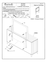
To connect a WCM to MUX and DMX modules, follow these steps:
Step 1 Remove the dust cover from one end of a jumper and the blind plug from the
WCM connector labeled R/T (remote transmitter). Connect the MiniSC plug to
the open connector.
Step 2 Remove the dust cover from the other end of the jumper and the blind plug from
the corresponding MUX connector. For example, if you interconnect the seventh
WCM, remove the blind plug from the MUX connector labeled 7. (See
Figure 5-1.)

5-3
Cisco Metro 1500 Series Hardware Installation Guide
78-10588-03
Chapter 5 Connecting Optical Cables
Connecting WCMs to MUX and DMX Modules
Figure 5-1 Connecting a WCM to a MUX and a DMX
Step 3 Remove the blind plug from the WCM connector labeled R/R (remote receiver)
and the dust cover from one end of a short jumper. Connect the MiniSC plug to
the open connector.
Step 4 Remove the dust cover from the other end of the jumper and the blind plug from
the corresponding DMX connector. For example, if you interconnect the seventh
WCM, remove the blind plug from the DMX connector labeled 7. (See
Figure 5-1.)
Step 5 Place the fiber-optic cables in the cable holder at the bottom of the chassis.
Repeat these steps with all other WCMs of the main chassis and extension chassis.
39489
L/T
R/T
R/R
L/R
Loop
On/Err
L/T
R/T
R/R
R/T
R/R
L/R
1-8(32)
MUX
8
M1
nc
8
8
6
4
2
1-8(32)
DMX
D1
nc
7
8
5
6
3
4
1
2
8

Chapter 5 Connecting Optical Cables
Connecting BSMs with MUX and DMX Modules
5-4
Cisco Metro 1500 Series Hardware Installation Guide
78-10588-03
Connecting BSMs with MUX and DMX Modules
To connect a BSM to MUX and DMX modules, follow these steps:
Step 1 Remove the dust cover from one end of a jumper and the blind plug from the MUX
connector labeled M1. (Use M1 if you are routing the MUX of the primary
chassis.) Connect the MiniSC plug to the open connector.
Step 2 Remove the dust cover from the other end of the jumper and the blind plug from
the BSM connector labeled M1. (Use M1 if you are routing the MUX of the
primary chassis.) Connect the MiniSC plug to the open connector of the BSM, as
shown in Figure 5-2.
Figure 5-2 Connecting a BSM to a MUX
Step 3 Remove the dust cover from one end of a jumper and the blind plug from the DMX
connector labeled D1. (Use D1 if you are routing the DMX of the primary
chassis.) Connect the MiniSC plug to the open connector.
1-8(32)
MUX
8
M1
nc
8
6
4
2
BSM
M1
D1
M2
D2
M3 D3
M4 D4
MD
39345
M1
M1
nc

5-5
Cisco Metro 1500 Series Hardware Installation Guide
78-10588-03
Chapter 5 Connecting Optical Cables
Connecting BSMs with MUX and DMX Modules
Step 4 Remove the dust cover from the other end of the jumper and the blind plug from
the BSM connector labeled D1. (Use D1 if you are routing the DMX of the
primary chassis.) Connect the MiniSC plug to the open connector of the BSM, as
shown in Figure 5-3.
Figure 5-3 Connecting a BSM to a DMX
Step 5 Place the fiber-optic cables in the cable holder of the primary and extension
chassis and the rack at the side of both chassis.
Note If you have an RSM installed, proceed to the “Connecting a BSM to
an RSM” section on page 5-6. Otherwise skip to the “Connecting
Remote Lines to a BSM” section on page 5-7
1-8(32)
DMX
D1
nc
7
8
5
6
3
4
1
2
BSM
M1
D1
M2
D2
M3 D3
M4 D4
MD
39344
M
D1
nc

Chapter 5 Connecting Optical Cables
Connecting a BSM to an RSM
5-6
Cisco Metro 1500 Series Hardware Installation Guide
78-10588-03
Connecting a BSM to an RSM
To connect a BSM to an optional RSM, follow these steps:
Step 1 Remove the dust cover from one end of a jumper and the blind plug from the BSM
connector labeled M. Connect the MiniSC plug to the open connector.
Step 2 Remove the dust cover from the other end of the blind plug from the RSM
connector labeled M. Connect the MiniSC plug to the open connector of the RSM,
as shown in Figure 5-4.
Figure 5-4 Connecting a BSM to an RSM
Step 3 Remove the dust cover from one end of a jumper and the blind plug from the BSM
connector labeled D. Connect the MiniSC plug to the open connector.
Step 4 Remove the dust cover from the other end of the jumper and the blind plug from
the RSM labeled D. Connect the plug to the open connector of the RSM, as shown
in Figure 5-4.
BSM
M1
D1
M2
D2
M3 D3
M4 D4
M
MD
D
Auto
L B
k
L A
k
L
k
A
On
B/T
B/R
M
D
A/T
A/R
B
M
D
39347

5-7
Cisco Metro 1500 Series Hardware Installation Guide
78-10588-03
Chapter 5 Connecting Optical Cables
Connecting Remote Lines to a BSM
Step 5 Place the fiber-optic cables in the cable holder of the primary and extension
chassis and the rack at the side of both chassis.
Note If you have a BSM installed, proceed to the “Connecting Remote
Lines to a BSM” section on page 5-7. Otherwise skip to the
“Connecting Remote Lines to RSMs” section on page 5-9.
Connecting Remote Lines to a BSM
To connect remote lines to a BSM, follow these steps:
Step 1 Remove the dust cover from the MiniSC plug of the remote transmission fiber of
line A, and clean the fiber as described in “Cleaning the Connectors” section on
page 3-19.
Step 2 Remove the blind plug from the BSM connector labeled M. Connect the cleaned
plug to the open connector of the BSM. (See Figure 5-5.)

Chapter 5 Connecting Optical Cables
Connecting Remote Lines to a BSM
5-8
Cisco Metro 1500 Series Hardware Installation Guide
78-10588-03
Figure 5-5 Connecting Remote Lines to a BSM
Step 3 Remove the dust cover from the MiniSC plug of the remote receiver fiber line, and
clean the fiber as described in the “Cleaning the Connectors” section on
page 3-19.
Step 4 Remove the blind plug from the BSM connector labeled D. Connect the cleaned
plug to the open connector of the BSM, as shown in Figure 5-5.
Step 5 Place the fiber-optic cables in the cable holder of the primary and extension
chassis and the rack at the side of both chassis.
Note If you have an optional RSM installed, proceed to the “Connecting
Remote Lines to RSMs” section on page 5-9. Otherwise skip to the
“Connecting Local Lines to WCMs” section on page 5-10.
BSM
M1
D1
M2
D2
M3 D3
M4 D4
MD
Direction of light
39346
MD

5-9
Cisco Metro 1500 Series Hardware Installation Guide
78-10588-03
Chapter 5 Connecting Optical Cables
Connecting Remote Lines to a BSM
Connecting Remote Lines to RSMs
To connect remote lines to an RSM, follow these steps:
Step 1 Remove the dust cover from the MiniSC plug of the remote transmission fiber of
line A, and clean the fiber as described in “Cleaning the Connectors” section on
page 3-19.
Step 2 Remove the blind plug from the RSM connector labeled A/T. Connect the cleaned
plug to the open connector of the RSM, as shown in Figure 5-6.
Figure 5-6 Connecting Remote Lines to an RSM
Auto
L B
k
L A
k
L
k
A
On
B/T
B/R
M
D
A/T
A/R
B
39359
Transmission fiber of line A
Transmission fiber of line B
Remote fiber of line B
Remote fiber of line A

Chapter 5 Connecting Optical Cables
Connecting Local Lines to WCMs
5-10
Cisco Metro 1500 Series Hardware Installation Guide
78-10588-03
Step 3 Remove the dust cover from the MiniSC plug of the remote receiver fiber of line
A, and clean the fiber as described in “Cleaning the Connectors” section on
page 3-19.
Step 4 Remove the blind plug from the RSM connector labeled A/R. Connect the cleaned
plug to the open connector of the RSM. (See Figure 5-6.)
Step 5 Remove the dust cover from the MiniSC plug of the remote transmission fiber of
line B, and clean the fiber as described in “Cleaning the Connectors” section on
page 3-19.
Step 6 Remove the blind plug from the RSM connector labeled B/T. Connect the cleaned
plug to the open connector of the RSM. (See Figure 5-6.)
Step 7 Remove the dust cover from the MiniSC plug of the remote receiver fiber of
line B, and clean the fiber as described in “Cleaning the Connectors” section on
page 3-19.
Step 8 Remove the blind plug from the RSM connector labeled B/R. Connect the cleaned
plug to the open connector of the RSM. (See Figure 5-6.)
Step 9 Place the fiber-optic cables in the cable holder of the primary and extension
chassis and the rack at the side of both chassis.
Connecting Local Lines to WCMs
To connect local lines to a WCM, follow these steps:
Step 1 Remove the dust cover from the MiniSC plug of the local receiver fiber and clean
the fiber as described in “Cleaning the Connectors” section on page 3-19.
Step 2 Remove the blind plug from the WCM connector labeled L/R. Connect the
cleaned plug to the open connector of the WCM. (See Figure 5-7.)

5-11
Cisco Metro 1500 Series Hardware Installation Guide
78-10588-03
Chapter 5 Connecting Optical Cables
Connecting Local Lines to WCMs
Figure 5-7 Connecting Local Lines to a WCM
Step 3 Remove the dust cover from the MiniSC plug of the local transmission fiber and
clean the fiber as described in “Cleaning the Connectors” section on page 3-19.
Step 4 Remove the blind plug from the WCM connector labeled L/T. Connect the
cleaned plug to the open connector of the WCM, as shown in Figure 5-7.
Step 5 Place the fiber-optic cables in the cable holder of the primary chassis and
extension chassis and the rack at the side of both chassis.
Step 6 Mount the acrylic cover on the front of the chassis.
L/T
R/T
R/R
L/R
Loop
On/Err
L/T
R/T
R/R
L/R
39360
Direction of light
Local transmission fiber
Local receiver fiber

Chapter 5 Connecting Optical Cables
Connecting Fiber Channel or Gigabit Ethernet to a High-Speed Transparent WCM
5-12
Cisco Metro 1500 Series Hardware Installation Guide
78-10588-03
Connecting Fiber Channel or Gigabit Ethernet to a
High-Speed Transparent WCM
When connecting a fiber channel or Gigabit Ethernet port to a high-speed
transparent WCM on the Cisco Metro 1500 series system, you must ensure that
the optical power levels from the fiber channel or Gigabit Ethernet transmitter do
not overdrive the local receiver (L/R) port on the WCM. To avoid an overdrive
condition, insert an optical attenuation of 5 dB between the fiber channel or
Gigabit Ethernet transmitter and the L/R port on the WCM. You can implement
this attenuation with either an attenuating single-mode patch cable assembly or an
attenuating coupler, which are described in the following sections.
Attenuating Single-Mode Patch Cable
An attenuating single-mode patch cable is a 9.84-ft (3 m) fiber-optic jumper cable
with a built-in attenuation of 5 db. (See Figure 5-8.)
Figure 5-8 Attenuating Single Mode Patch Cable Assembly
The attenuating single-mode patch cable assembly should contain Corning
SMF-28 or equivalent single-mode fiber.
Attenuating Coupler
As an alternative to the attenuating single-mode patch cable, you can use a 5-dB
attenuating coupler. (See Figure 5-9.)
Blue MiniSC (MUPC)
single-mode connector
Blue SC
single-mode connector
5-dB
Yellow jacket
SMF SMF
3 meters
(9.84 feet)
39362

5-13
Cisco Metro 1500 Series Hardware Installation Guide
78-10588-03
Chapter 5 Connecting Optical Cables
Connecting Fiber Channel or Gigabit Ethernet to a High-Speed Transparent WCM
Figure 5-9 Attenuating Coupler
Figure 5-9 shows a conventional MiniSC to SC patch cable, plus the attenuating
coupler, which achieves the same effect as the attenuating single-mode patch
cable assembly with the built-in attenuation.
Other Limitations and Restrictions
The following limitations and restrictions for connecting fiber channel or Gigabit
Ethernet to a high-speed transparent WCM:
• The coupling facility currently requires that at least two LPARs be active for
the link to activate and that the link between the two sites be no longer than
15.5 mi (25 km). Installation of the card requires that an LPAR be cycled to
clear the loop condition created by the card. If only one LPAR is present, the
optical interface is cycled with the LPAR and the loop is once again
established.
• When using low-speed applications (200 Mbps and below) with high-speed
cards, the application is typically overdriven. As a workaround, add
attenuation to the signal coming from the local transmitter port of the
Cisco Metro 1500 series system.
• Do not use a multimode patch cable that has been attenuated using
core-shifted splicing to attenuate the signal coming from a
Cisco Metro 1500 series system. The system interface is always a
single-mode laser and the attenuation is not consistent or reliable. In addition,
for all interfaces, avoid air-gap attenuators, which have high back reflection
that may cause bit errors on the connection.
MiniSC (MUPC)
single-mode connector
SC
single-mode connector
5-dB
Attenuating
coupler
SMF
39363
5-dB

Chapter 5 Connecting Optical Cables
Connecting Optical Isolators
5-14
Cisco Metro 1500 Series Hardware Installation Guide
78-10588-03
Caution When connecting Cisco Metro 1500 series systems, you must
adhere to the minimum remote link budget, as called out in
Table A-9 on page A-15. If you do not adhere to this minimum
budget, you might damage the receivers of the channel cards. This
damage can only be repaired at the factory and is not covered by the
warranty.
Connecting Optical Isolators
The Cisco Metro 1500 series optical isolator allows direct transmission from a
WCM over a remote (or trunk) fiber. The optical isolator enables a WCM to
bypass the multiplexer/demultiplexer(MUX/DMX)module in the systemchassis.
By connecting the WCM to the optical isolator through fiber jumpers, you can
transmit directly over the remote fiber and obtain an additional 3 dB to 5 dB for
use in your optical budget.
The optical isolator minimizes optical back reflection. Optical back reflection is
common in fiber-based transmissions. Back reflection is a small amount of light
that is reflected back towards the transmitting optical component. The optical
isolator absorbs this reflected light so that the transmitting optical component
operates with minimal interference.
Installation Notes
The optical isolator is connected directly to a jumper that extends from the remote
connection of the WCM. The optical isolator sits between the WCM and the
remote (or trunk) fiber. (See Figure 5-10.)

5-15
Cisco Metro 1500 Series Hardware Installation Guide
78-10588-03
Chapter 5 Connecting Optical Cables
Connecting Optical Isolators
Figure 5-10 Optical Isolator Connection Scenario
To connect the optical isolator, follow these guidelines:
• The optical connector coming out of a WCM is MUPC type. Cisco stocks
fiber jumpers that use an MU-to-SC type connection. This is the standard
jumper configuration. However, the isolator can be used with a number of
different connector types, if needed.
• The fiber jumper coming out of the WCM is connected to the fiber attached
to the optical isolator. For example, two SC connectors are connected.
• The fiber on the other side of the optical isolator is connected to the trunk or
remote fiber. For example, two SC connectors are connected.
L/T
R/T
R/R
L/R
Loop
On/Err
L/T
R/T
R/R
L/R
Card connector
(MiniSC)
Optical isolator Trunk connector
(ST of FC/PC or MiniSC)
Trunk or RSM
connectors
WCM
42292

Chapter 5 Connecting Optical Cables
Testing a Remote Link
5-16
Cisco Metro 1500 Series Hardware Installation Guide
78-10588-03
Testing a Remote Link
The remote loopback feature of the WCM allows you to test the remote optical
communications link without disconnecting the system. You must test the remote
link to verify that it meets the specifications to ensure proper operation. Tests may
already be available from the supplier of the fiber. If no report is available,
perform the tests to verify that parameters are within specifications.
Table 5-1 lists the tests required for the remote link and the equipment required to
perform each test.
To test a remote optical communications link, follow these steps:
Step 1 Disconnect the local lines from the WCMs at both the local and remote systems
in the link to be tested.
Step 2 Supply a modulated light to the local receiver of the WCM.
This modulated light switches on the local receiver and the remote transmitter of
the local system. The green L/R LED should be on. If the modulated light does
not match the clock recovery frequency, assuming a clock recovery is installed
and enabled, the Error Indicator LED will be red.
Step 3 Set the remote loopback of the corresponding WCM of the remote system.
The orange loop LED of the WCM in the remote system should be on. The remote
receiver, the remote transmitter, and the local transmitter should operate and
loopback the received signal to the local system. The R/R, R/T, and L/T LEDs
Table 5-1 Tests and Equipment Required
Tests Equipment Required
Optical link loss 1550 nm
specified in dBm referenced to
1mW
• Laser source at 1310 nm and 1550 nm
• A power meter or OTDR
1
1. OTDR = optical time domain reflectometer
Distance specified in km OTDR
Optical return loss 1550 nm
specified in dB
Reflectometer
or
OTDR with a reflectometer

5-17
Cisco Metro 1500 Series Hardware Installation Guide
78-10588-03
Chapter 5 Connecting Optical Cables
Testing a Remote Link
should be on. If the modulated light does not match the clock-recovery frequency,
assuming a clock recovery is installed and enabled, the R/R LED will be red. The
remote receiver of the local system sees the signal and transfers it to the local
transmitter. The WCM in the local system should have the L/T, L/R, R/T, and R/R
LEDs on.
Note If your test results deviate from these results and you cannot correct
the problem, contact your Cisco service representative.

Chapter 5 Connecting Optical Cables
Testing a Remote Link
5-18
Cisco Metro 1500 Series Hardware Installation Guide
78-10588-03
/