Honeywell HD28C4HR9 User manual
- Category
- Security cameras
- Type
- User manual

Document 900.0275 – 10/05 – Rev 1.01
Installation Guide
Premium Vandal
Dome Camera
NTSC / PAL
HD28C4HR6 HD28C4HR6X
HD28C4HR9 HD28C4HR9X
HD28W4HR6 HD28W4HR6X
HD28W4HR9 HD28W4HR9X
HD28D4HR6 HD28D4HR6X
HD28D4HR9 HD28D4HR9X

Revisions
Issue Date Revisions
1.00 09/05 New document.
1.01 10/05 Changed HD28R to HD28 throughout,
removed utp & fiber termination boards
updated back cover.
Rev 1.01 ii Document 900.0275
10/05

Rev 1.01 iii Document 900.0275
10/05
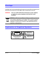
Warnings
Installation and servicing should be performed only by qualified and experienced
technicians to conform to all local codes and to maintain your warranty.
WARNING! The use of CSA Certified/UL Listed Class 2 power adapters
is required to ensure compliance with electrical safety
standards.
Explanation of Graphical Symbols
WEEE (Waste Electrical and Electronic Equipment). Correct disposal
of this product (applicable in the European Union and other European
countries with separate collection systems). This product should be
disposed of, at the end of its useful life, as per applicable local laws,
regulations, and procedures.
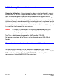
RISK OF ELECTRIC
SHOCK
DO NOT OPEN
CAUTION: TO REDUCE THE RISK OF ELECTRIC
SHOCK, DO NOT REMOVE THE COVER.
NO USER-SERVICEABLE PARTS INSIDE
REFER SERVICING TO QUALIFIED
SERVICE PERSONNEL
THIS SYMBOL INDICATES THAT
DANGEROUS VOLTAGE
CONSTITUTING A RISK OF
ELECTRIC SHOCK IS PRESENT
WITHIN THE UNIT.
THIS SYMBOL INDICATES THAT
IMPORTANT OPERATING AND
MAINTENANCE INSTRUCTIONS
ACCOMPANY THIS UNIT.
CAUTION

Rev 1.01 iv Document 900.0275
10/05
FCC Compliance Statement
Information to the User: This equipment has been tested and found to comply
with the limits for a Class A digital device. Pursuant to Part 15 of the FCC Rules,
these limits are designed to provide reasonable protection against harmful
interference when the equipment is operated in a commercial environment. This
equipment generates, uses, and can radiate radio frequency energy and, if not
installed and used in accordance with the instruction manual, may cause harmful
interference to radio communications. Operation of this equipment in a residential
area is likely to cause harmful interference in which case the user will be required
to correct the interference at his own expense.
Caution Changes or modifications not expressly approved by the party
responsible for compliance could void the user’s authority to
operate the equipment.
This Class A digital apparatus complies with Canadian ICES-003.
Cet appareil numérique de la Classe A est conforme à norme NMB-003 du
Canada.
Manufacturer’s Declaration of Conformance
The manufacturer declares that the equipment supplied with this guide is
compliant with the essential protection requirements of the EMC directive 89/336/
EEC and the Low Voltage Directive LVD 73/23 EEC, conforming to the
requirements of standards EN 55022 for emissions.

Rev 1.01 Document 900.0275
10/05
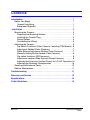
Contents
Introduction . . . . . . . . . . . . . . . . . . . . . . . . . . . . . . . . . . . . . . . . . . . . 1
Before You Begin . . . . . . . . . . . . . . . . . . . . . . . . . . . . . . . . . . . . . . .1
Unpack Everything . . . . . . . . . . . . . . . . . . . . . . . . . . . . . . . . . . . .1
Equipment Required . . . . . . . . . . . . . . . . . . . . . . . . . . . . . . . . . .1
Installation . . . . . . . . . . . . . . . . . . . . . . . . . . . . . . . . . . . . . . . . . . . . 2
Mounting the Camera . . . . . . . . . . . . . . . . . . . . . . . . . . . . . . . . . . . .2
Preparing the Mounting Surface. . . . . . . . . . . . . . . . . . . . . . . . . 2
Installing the Conduit Plug . . . . . . . . . . . . . . . . . . . . . . . . . . . . . .3
Wiring Options . . . . . . . . . . . . . . . . . . . . . . . . . . . . . . . . . . . . . . .4
Connecting the Wiring . . . . . . . . . . . . . . . . . . . . . . . . . . . . . . . . .4
Adjusting the Camera . . . . . . . . . . . . . . . . . . . . . . . . . . . . . . . . . . . .5
Dip Switch Functions (Color Cameras, Including TDN Models) .6
Adjustment Method (Color Cameras) . . . . . . . . . . . . . . . . . . . . .7
White Balance Adjustment Method (Color Cameras) . . . . . . . . .7
Manually Setting Shutter Speed (Color Cameras) . . . . . . . . . . .8
Dip switch functions (WDR cameras) . . . . . . . . . . . . . . . . . . . . . 9
Adjustment method (Wide Dynamic Range Cameras) . . . . . . . .9
Adjusting the Line Lock (Vertical Phase) for 24 VAC Operation 10
Adjusting the Backlight Compensation . . . . . . . . . . . . . . . . . . .10
Securing the Enclosure Cover . . . . . . . . . . . . . . . . . . . . . . . . . . . .10
Routine Maintenance . . . . . . . . . . . . . . . . . . . . . . . . . . . . . . . . . . .11
Troubleshooting . . . . . . . . . . . . . . . . . . . . . . . . . . . . . . . . . . . . . . . 11
Warranty and Service . . . . . . . . . . . . . . . . . . . . . . . . . . . . . . . . . . . 12
Specifications . . . . . . . . . . . . . . . . . . . . . . . . . . . . . . . . . . . . . . . . . 13
Cable Guidelines . . . . . . . . . . . . . . . . . . . . . . . . . . . . . . . . . . . . . . . 14

Rev 1.01 1 Document 900.0275
10/05
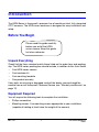
Introduction
The HD28 Series is Honeywell’s premium line of vandal-resistant, fully-integrated
CCTV cameras. The HD28 series enclosure is designed for easy installation and
setup.
Before You Begin
Unpack Everything
Check that the items received match those listed on the order form and packing
slip. The HD28 series packing box should include, in addition to this User Guide
• One HD28 series camera
• One hardware kit
• One mounting template
• One product warranty
If any parts are missing or damaged, contact the dealer you purchased the
camera from or call Honeywell Customer Service (see “Warranty and Service” on
page 12).
Equipment Required
You will require the following tools to complete the installation:
• Phillips screwdriver
• Mounting screws. Use mounting screws appropriate to your installation
(capable of holding at least twice the weight of the camera).
Please read this guide carefully
before you install the HD28
series camera. Keep this guide
for future reference.

Rev 1.01 2 Document 900.0275
10/05
Installation
Your HD28 camera is weather-sealed for indoor or outdoor locations. The wiring
can be completely concealed for maximum vandal and tamper resistance.
Mounting the Camera
The HD28 camera is designed to be surface mounted on a wall or ceiling.
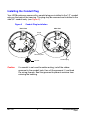
Preparing the Mounting Surface
1. Affix the mounting template to the mounting surface (see Figure 1).
2. Pre-drill four holes as indicated on the template, using the recommended
hole size for the screws being used.
3. Drill out the conduit hole, if required (see Installing the Conduit Plug).
4. Connect the wiring (see Connecting the Wiring).
5. Mount the camera base to the wall or ceiling using mounting screws (not
supplied) capable of holding at least twice the weight of the camera.
Note Alternate fasteners (preferably stainless steel) can be used, provided
they are not larger than the screw holes on the mounting template.
Figure 1 Mounting Template Guide
W
a
l
l
M
o
u
n
t
r
e
c
o
m
m
e
n
d
e
d
t
h
i
s
w
a
y
Mounting screws
appropriate to your
installation (not
supplied)

Rev 1.01 3 Document 900.0275
10/05
Installing the Conduit Plug
Your HD28 enclosure comes with a conduit plug pre-installed in the 1/2” conduit
entry on the back of the housing. This plug may be removed and installed in the
side 3/4” conduit entry (see Figure 2).
Figure 2 Conduit Plug Installation
Caution If a conduit is not used for cable routing, install the rubber
grommet in the conduit hole, then slit the grommet and feed
the wiring through. Seal the grommet to prevent moisture from
entering the housing.
Back View Side View
Screw
Retainer plate
Gasket
Conduit plug

Rev 1.01 4 Document 900.0275
10/05
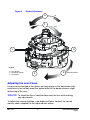
Wiring Options
Your HD28 Series camera is supplied with a coaxial termination board mounted
to the bottom of the enclosure. All connections are made here (see Figure 3).
Figure 3 Wiring Options
Connecting the Wiring
1. Pull the cables through either the back or the side conduit.
2. To minimize moisture leaking into the housing, position the enclosure with
the conduit pointing down. Apply an appropriate sealant around the conduit
connection.
Adjusting the Camera
To adjust the HD28 camera:
1. Apply 12 VDC or 24 VAC to the camera and monitor the video signal.
2. Loosen the screws that lock the gimbal assembly in place (see Figure 4).
3. Adjust the camera carrier to the desired view (see Figure 4).
4. Tighten the screws to lock the gimbal assembly in place.
Note Orient the camera as shown in Figure 4 to maintain the correct
picture orientation.
Coax Termination Board
Case/
Ground
Not used
Power
Audio
Video

Rev 1.01 5 Document 900.0275
10/05
Figure 4 Gimbal Adjustment
Adjusting the Lens Focus
Lenses are pre-focused at the factory but may require a final adjustment after
installation in the unlikely event the optical effect of the dome causes a slight
defocusing of the lens.
TECH TIP! To check the focus, hold the dome over the lens while making
any adjustments.
To adjust the camera direction, view angle and focus, connect the service
monitor cable (supplied) to the video monitor output.
Tilt
Pan
Horizontal rotation
3
1
2
3
1
2
Legend
1 = Pan rotation
2 = Horizontal rotation
3 = Tilt rotation

Rev 1.01 6 Document 900.0275
10/05
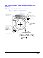
Dip Switch Functions (Color Cameras, Including TDN
Models)
Follow Figure 5 to set the dip switches on a color camera.
Figure 5 Color Camera Switch Settings
ON
OFF
ON
OFF
1 2 3 4 5 6 7 8 9 10
GAMMA
AE
FLON
BLC
IRIS
N/A *
AGC MAX
AWB1
AWB2
AWB3
Push lock
Video monitor
output
Upper locking
screw to set focus
Lower locking
screw to set focal
length
Line-lock adjustment
Auto Iris Level Adj.
(Varifocal lens).
Turn screw
clockwise to
increase
brightness level.
* Not used. Leave
in Off position.
Factory (default) settings
= ON (up)
= OFF (down)
12345678910

Rev 1.01 7 Document 900.0275
10/05
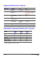
Adjustment Method (Color Cameras)
White Balance Adjustment Method (Color Cameras)
Switch no. Function Off On
1 GAMMA Off (0.45) On (1.0)
2AE (Automatic
Exposure)
Off On (see Manually Setting
Shutter Speed (Color
Cameras))
3FLON (Flicker
Less)
Off On
4BLC (Backlight
Compensation)
Off On (Center window)
5 IRIS Control Electronic
IRIS
Auto IRIS
6 Not used Not used Not used
7 AGC 4 dB 26 dB
Symbol SWB8
AWB1
SWB9
AWB2
SW10
AWB3
AWB Off Off Off
ATW Off On Off
Push lock Off On On *
Indoor (3200° K) On Off On
Outdoor (6500° K) On On On
* To manually set Push lock feature: place a white background in front of
camera and press “Push lock” switch.

Rev 1.01 8 Document 900.0275
10/05
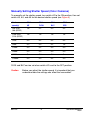
Manually Setting Shutter Speed (Color Cameras)
To manually set the shutter speed, turn switch #2 to the ON position; then set
switch #3, #4, and #5 for the desired shutter speed (see Figure 5).
FLON and BLC can be set when switch #2 is set to the OFF position.
Caution Before you adjust the shutter speed, it is important that you
understand how the settings can affect the scene detail.
Shutter
speed(s)
SW2
AE
SW3
FLON
SW4
BLC
SW5
IRIS
1/50 (PAL)
1/60 (NTSC)
On Off On Off
1/100 (PAL)
1/120 (NTSC)
On On On Off
1/250 On Off Off Off
1/500 On On Off Off
1/1000 On Off On On
1/2000 On On On On
1/4000 On Off Off On
1/10000 On On Off On

Rev 1.01 9 Document 900.0275
10/05
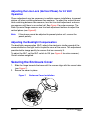
Dip switch functions (WDR cameras)
Figure 6 Wide Dynamic Range Camera Switch Settings
Note The Wide Dynamic Range camera has been designed for the best
wide dynamic performance and can only be used with vari-focal
auto iris lenses.
Adjustment method (Wide Dynamic Range Cameras)
Switch No. Function Off On
1 EE/DC IRIS EE IRIS DC IRIS
2 AWB/ATW AWB ATW
3 WDR (Wide Dynamic Range) Off On
4 AGC Off On
5
MIRROR Off On
Video
monitor
output
Auto Iris level
adjustment. If
necessary, turn
clockwise to increase
brightness level.
= ON (up)
= OFF (down)
EE/DC IRIS
AWB/ATW
WDR
AGC
MIRROR
Line-lock
adjustment
Upper locking
screw to set
focus
Lower locking
screw to set
focal length
Factory (default) settings

Rev 1.01 10 Document 900.0275
10/05
Adjusting the Line Lock (Vertical Phase) for 24 VAC
Operation
Phase adjustment may be necessary in multiple camera installations to prevent
picture roll when switching between two cameras. To adjust the vertical phase
while switching between two cameras, turn the Line lock adjustment screw on
one camera until there is no vertical roll. See Figure 5 for color cameras. The
Wide Dynamic Range cameras use line lock adjustment buttons to adjust the
vertical phase (see Figure 6).
Note If the phase cannot be adjusted to prevent picture roll, reverse the
power polarity.
Adjusting the Backlight Compensation
The backlight compensation (BLC) adjusts the electronic shutter speed of the
camera based on the light levels in specific areas of the scene. This adjustment
provides better image quality for scenes that are unevenly lit.
To adjust the BLC, set the BLC switch to ON (see Figure 5 for color cameras).
Center window weighted.
Securing the Enclosure Cover
1. Slide the hinge towards the base until the screws align with the screw holes
(see Figure 7).
2. Secure the cover in place.
Figure 7 Enclosure Cover Installation

Rev 1.01 11 Document 900.0275
10/05
Routine Maintenance
Use regular liquid cleaners to remove dirt and grime from the dome.
Caution Do not use harsh or abrasive cleaners which can scratch the
polycarbonate dome and reduce visibility for the camera.
If the camera view is obstructed by scratches, remove the front plate and rotate to
find an unscratched part of the dome.
Troubleshooting
No video
Check:
• Power supply voltage is within the operating specifications for your camera
model (see Troubleshooting).
• Video connections to the monitor or CCTV system.
• The camera connections to the terminal board.
• Video switcher or other equipment connections. To eliminate video
problems, connect a video monitor directly to the HD28 video output cable.
Noisy video
Check:
• Video ground connections
• For ground loops.
For additional assistance, call Honeywell Customer Service (see below).

Rev 1.01 12 Document 900.0275
10/05
Warranty and Service
Subject to the terms and conditions listed on the product warranty, during the
warranty period Honeywell will repair or replace, at its sole option, free of charge,
any defective products returned prepaid.
In the event you have a problem with any Honeywell product, please call
Customer Service at 1.800.796.2288 for assistance or to request a Return
Merchandise Authorization (RMA) number.
Be sure to have the model number, serial number, and the nature of the problem
available for the technical service representative.
Prior authorization must be obtained for all returns, exchanges, or credits. Items
shipped to Honeywell without a clearly identified Return Merchandise
Authorization (RMA) number may be refused.

Rev 1.01 13 Document 900.0275
10/05
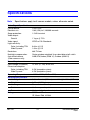
Specifications
Note Specifications apply to all camera models, unless otherwise noted.
Video Signal Specifications
Pickup device: 1/3 in. CCD
Electronic iris: 1/60 (1/50) to 1/100,000 seconds
Surge protection: 1.5 kW transient
Video output:
Coaxial 1 V p-p @ 75 Ω
Video signal: NTSC or PAL Standards
Light sensitivity:
Color, Including TDN 0.6 lux @ f1.5
Wide Dynamic 1.0 lux @ f1.5
Resolution: 480 TV lines
Backlight compensation: Center window weighted. User-selectable on/off switch
Auto white balance:
(Color cameras only)
AWB/ATW/Indoor (3200° K), Outdoor (6500° K)
Power Requirements
Input voltage (at camera): 15 VDC (11-16V) or 24 VAC
Current consumption:
Color, including TDN 3.5W (complete system)
Wide Dynamic 4.5W (complete system)
Operating Temperature -13°F to 122°F (-25°C to 50°C)
Housing Specifications
Housing dimensions: 6.1 in. diameter (150 mm), overall height 4.13 in. (115 mm)
Weight 3.0 lbs. (1.37 kg)
Housing material: Die cast aluminum alloy
Finish: Urethane powder paint
Dome material: Hard coated polycarbonate (clear dome with insert)
Ratings FCC Part 15B
Œ, Meets IP66, UL2044

Rev 1.01 14 Document 900.0275
10/05
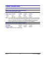
Cable Guidelines
Power supply cable maximum length (feet/meters)
Cameras with AC/DC power supplies
Wire gauge
Power supply 24 AWG 22 AWG 18 AWG 16 AWG
15 VDC 45/14 73/22 185/56 295/90
24 VAC 408/125 660/201 1674/510 2664/812
Note Calculations are based on an unregulated linear power supply which would be the
worst case. Using a regulated or switching power supply can increase the cable
distance. Honeywell recommends using a CSA Certified/UL listed Class 2
power supply to ensure compliance with electrical safety standards.
Coaxial video cable maximum length (feet/meters)
Cable type RG-59 RG-6 RG-11
Wire gauge 23 AWG* 18 AWG* 14 AWG*
Maximum length 750/229 1500/457 2000/610
* Copper clad steel core, 95% braided shield

Video Systems
www.honeywellvideo.com
+1.800.796.CCTV (North America only)
© 2005 Honeywell International Inc.
All rights reserved. No part of this publication may be reproduced by any means without written
permission from Honeywell Video Systems. The information in this publication is believed to be accurate
in all respects. However, Honeywell Video Systems cannot assume responsibility for any consequences
resulting from the use thereof. The information contained herein is subject to change without notice.
Revisions or new editions to this publication may be issued to incorporate such changes.
Honeywell Security Australia Pty Ltd.
Unit 5, Riverside Centre, 24-28 River Road West
Parramatta, NSW 2150, Australia
www.ademco.com.au
℡
+61.2.8837.9300
Honeywell Security Asia Pacific
Flat A, 16/F, CDW Building, 388 Castle Peak
Road
Tsuen Wan, N.T., Hong Kong
www.security.honeywell.com/hk
℡
+852.2405.2323
Honeywell Security France
Parc Gutenberg, 8, Voie La Cardon
91120, Palaiseau, France
www.honeywell-security.fr
℡
+33.01.6932.1090
Honeywell Security Italia SpA
Via della Resistenza 53/59, 20090 Buccinasco
Milan, Italy
www.security.honeywell.com/it
℡
+39.02.457.1791
Honeywell Security Espana
Calle Vivero, 5, 28040
Madrid, Spain
www.security.honeywell.com/es
℡
+34.91.102.5900
Honeywell Security Nederland
Netwerk 121
1446 WV Purmerend, Netherlands
www.SecurityHouse.nl
℡
+31.299.410.200
Honeywell Video Systems (Head Office)
2700 Blankenbaker Pkwy, Suite 150
Louisville, KY 40299, USA
www.honeywellvideo.com
℡
+1.800.796.2288
Honeywell Video Systems UK Ltd.
Aston Fields Road, Whitehouse Ind Est
Runcorn, Cheshire, WA7 3DL, UK
www.security.honeywell.com
℡
+44.1928.754.030
Honeywell Security South Africa
Unit 6 Galaxy Park, 17 Galaxy Avenue, Linbro Park
P.O. Box 59904, Kengray, 2100, South Africa
www.honeywell.co.za
℡
+27.11.574.2500
Honeywell Security Germany
Großenbaumer Weg 8
40472 Düsseldorf, Germany
www.honeywell-security.de
℡
+49.211.41.50.90
Honeywell Security Poland
Chmielewskiego 22a, 70-028
Szczecin, Polska
www.ultrak.pl
℡
+48.91.485.40.60
Honeywell Security Czech Republic
Havránkova 33, Brno
Dolní Heršpice, 619 00, Czech Republic
www.olympo.cz
℡
+420.543.558.111
Honeywell Security Slovakia Republic
Vajnorskà 142, 83104 Bratislava
Slovakia
www.olympo.sk
℡
+421.2.444.54.660
-
 1
1
-
 2
2
-
 3
3
-
 4
4
-
 5
5
-
 6
6
-
 7
7
-
 8
8
-
 9
9
-
 10
10
-
 11
11
-
 12
12
-
 13
13
-
 14
14
-
 15
15
-
 16
16
-
 17
17
-
 18
18
-
 19
19
-
 20
20


Honeywell HD28C4HR9 User manual
- Category
- Security cameras
- Type
- User manual
Ask a question and I''ll find the answer in the document
Finding information in a document is now easier with AI
Related papers
-
Honeywell HD3VC4SHR User manual
-
Honeywell YTH8320ZW1064 Operating instructions
-
-
-
-
-
-
-
Honeywell HMLCD19e2 User manual
-
Other documents
-
 TOA Electronics C-CV202-3 CU User manual
-
i3 International DB78TSB Quick start guide
-
Insignia HD16 User manual
-
 Videology CS Operating instructions
-
Innotech SmartControl EXCA234CAT5 Series Quick Installation Manual
-
Channel Plus 7440 User manual
-
Eneo VKC-1382/IR316 Installation And Operating Instructions Manual
-
Samsung SCB-5003N User manual
-
Samsung SCB-3003 User manual
-
Digimerge DPD24W User manual

