Page is loading ...

INSTALLATION INSTRUCTIONS
Weatherproof Series,
150mm (6 inch) and 200mm (8 inch)
Fire Alarm Bell, Type B
Please ensure that the following instructions are
read carefully prior to installation.
1. Bells should be positioned a minimum of 2.4m
above the floor, in the vertical plane.
2. Remove gong by unscrewing allen/hex bolt.
3. Ensure that the terminals are at the top left
side of the unit; feed field wiring through the
base. For outdoor use the base should be
mounted on the enclosed back box.
One 20mm threaded cable entry is available.
(Fig 2/3)
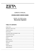
4. Connect wiring (max 2.5mm ) to terminals (Fig
1) observing polarity. Dress wires to avoid
touching the gong.
5. Correctly align gong on base and replace
bolt to secure.
2
allen/hex
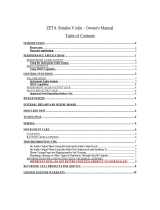
Fig 2: Surface Installation
Please Note: Care should be taken to
avoid damage to the striker mechanism
Fig 3: Basic Mechanism and Gongs
Mounting Holes (Dimensions in mm)
Field Wiring
Max. 2.5mm
2
From
control
panel
SPECIFICATION
Model
Rated Voltage +/-15% 24Vdc 24Vdc
Rated Current at 24Vdc 12mA 25mA
ZTB6B/WP ZTB8B/WP
Operating Temperature -10 to +50 C -10 to +50 C
IP Rating (minimum) 33C 33C
Weight 780g 1100g
Body Colour Red Red
oo
Fig 1: Wiring (rear view) Observe Polarity
Note: For sound output data refer to Sound Output Data Sheet DS/BELLDATA/ZETA/ISS1
Fire Alarm Bells manufactured for ZETA Alarms Ltd. UK
E&OE
Ref: IS/3500017/ZETA iss 1
www.zeta-alarms.co.uk
Gong
Installation box
with 20mm
threaded entry
Allen/Hex bolt
Mounting
Screw
Gasket
Base
Mounting holes are located on the bell base to suit
installation back box supplied.
64
40
(Back box + gasket)
128
150 or 200
7
95
To next bell or
end-of-line
monitoring
device
(Polarised)
INSTALLATION INSTRUCTIONS
Weatherproof Series,
150mm (6 inch) and 200mm (8 inch)
Fire Alarm Bell, Type B
Please ensure that the following instructions are
read carefully prior to installation.
1. Bells should be positioned a minimum of 2.4m
above the floor, in the vertical plane.
2. Remove gong by unscrewing allen/hex bolt.
3. Ensure that the terminals are at the top left
side of the unit; feed field wiring through the
base. For outdoor use the base should be
mounted on the enclosed back box.
One 20mm threaded cable entry is available.
(Fig 2/3)
4.
2
Connect wiring (max 2.5mm ) to terminals (Fig
1) observing polarity. Dress wires to avoid
touching the gong.
5. Correctly align gong on base and replace
allen/hex bolt to secure.
Fig 2: Surface Installation
Please Note: Care should be taken to
avoid damage to the striker mechanism
Fig 3: Basic Mechanism and Gongs
Mounting Holes (Dimensions in mm)
Field Wiring
Max. 2.5mm
2
From
control
panel
SPECIFICATION
Model
Rated Voltage +/-15% 24Vdc 24Vdc
Rated Current at 24Vdc 12mA 25mA
ZTB6B/WP ZTB8B/WP
Operating Temperature -
o
10 to +50 C
IP Rating (minimum) 33C 33C
Weight 780g 1100g
Body Colour Red Red
-10 to +50 C
o
Fig 1: Wiring (rear view) Observe Polarity
Note: For sound output data refer to Sound Output Data Sheet DS/BELLDATA/ZETA/ISS1
Fire Alarm Bells manufactured for ZETA Alarms Ltd. UK
E&OE
Ref: IS/3500017/ZETA iss 1
www.zeta-alarms.co.uk
Gong
Installation box
with 20mm
threaded entry
Allen/Hex bolt
Mounting
Screw
Gasket
Base
Mounting holes are located on the bell base to suit
installation back box supplied.
64
40
(Back box + gasket)
128
150 or 200
7
95
To next bell or
end-of-line
monitoring
device
(Polarised)
/