Greenlee UT4, UT4-22 Cable Pulling System AMJ, ABL User manual
- Category
- Toys
- Type
- User manual

INSTRUCTION MANUAL
UT4 and UT4-22
Cable Pulling Systems
Serial Codes AMJ and ALB
52041928 REV 11 © 2014 Greenlee Textron Inc. 12/14
Read and understand all of the instructions and
safety information in this manual before operating
or servicing this tool.
Register this product at www.greenlee.com

UT4 and UT4-22 Cable Pulling Systems
Greenlee / A Textron Company 4455 Boeing Dr. • Rockford, IL 61109-2988 USA • 815-397-7070
2
Description
The Greenlee UT4 and UT4-22 Cable Pulling Systems
are intended to pull cable through conduit for medium-
duty applications.
Typical applications might be: pulling
3x500 kcmil (mcm)
cables 300 feet or 3x3/0 cables
600feet.
Safety
Safety is essential in the use and maintenance of
Greenlee tools and equipment. This manual and any
markings on the tool provide information for avoiding
hazards and unsafe practices related to the use of this
tool. Observe all of the safety information provided.
Purpose of this Manual
This manual is intended to familiarize all personnel with
the safe operation and maintenance procedures for the
following Greenlee tools:
UT4 Cable Pulling System
UT4-22 Cable Pulling System
Keep this manual available to all personnel.
Replacement manuals are available upon request at no
charge at www.greenlee.com.
All specications are nominal and may change as design
improvements occur. Greenlee Textron Inc. shall not be liable for
damages resulting from misapplication or misuse of its products.
KEEP THIS MANUAL
Table of Contents
Description .................................................................... 2
Safety ............................................................................ 2
Purpose of this Manual ................................................. 2
Important Safety Information ..................................... 3-5
Specications ................................................................ 6
Initial Assembly ............................................................. 7
Assembly ....................................................................... 8
Setup
Up-pull ................................................................. 9-10
Down-pull ................................................................ 11
Floor Mount ............................................................. 12
Operation ................................................................ 13-14
Maintenance ................................................................ 15
Illustrations and Parts Lists .................................... 16-19
Nose Assembly ........................................................ 16
Floor Mount ............................................................. 16
UT4 .......................................................................... 17
Gear Motor Assembly .............................................. 18
Control Box .............................................................. 19

UT4 and UT4-22 Cable Pulling Systems
Greenlee / A Textron Company 4455 Boeing Dr. • Rockford, IL 61109-2988 USA • 815-397-7070
3
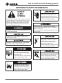
IMPORTANT SAFETY INFORMATION
SAFETY
ALERT
SYMBOL
This symbol is used to call your attention to hazards
or unsafe practices which could result in an injury or
property damage. The signal word, dened below,
indicates the severity of the hazard. The message
after the signal word provides information for pre-
venting or avoiding the hazard.
Immediate hazards which, if not avoided, WILL result
in severe injury or death.
Hazards which, if not avoided, COULD result in
severe injury or death.
Hazards or unsafe practices which, if not avoided,
MAY result in injury or property damage.
Read and understand all of the
instructions and safety information
in this manual before operating or
servicing this tool.
Failure to observe this warning could
result in severe injury or death.
Do not operate the cable puller in
a hazardous environment. Hazards
include ammable liquids and gases.
Failure to observe this warning will
result in severe injury or death.
Electric shock hazard:
Disconnect the cable puller from
the power source before servicing.
Failure to observe this warning could
result in severe injury or death.
Attach only to steel or schedule 40 PVC conduit.
Do not attach to PVC conduit unless it is supported
within 2" of the end.
Failure to observe this warning could result in severe
injury or death.
Do not allow anything other than the
pulling rope to contact the capstan.
A grip, swivel, or other component
could break and strike nearby
personnel with great force.
Failure to observe this warning could
result in severe injury or death.
Do not stand directly under a vertical
pull. Cable could fall suddenly from the
conduit, injuring nearby personnel.
Failure to observe this warning could
result in severe injury or death.

UT4 and UT4-22 Cable Pulling Systems
Greenlee / A Textron Company 4455 Boeing Dr. • Rockford, IL 61109-2988 USA • 815-397-7070
4
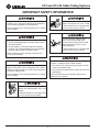
IMPORTANT SAFETY INFORMATION
An under-rated or worn rope may break and whip
violently. Use a polyester or polyester-jacketed rope
with a breaking strength of 16,000 pounds.
Failure to observe this warning could result in severe
injury or death.
• Check the condition of the entire rope before use.
A worn or damaged rope can break under tension
and whip violently.
• Do not maintain a stationary rope on a rotating
capstan. The wear generated may cause the rope
to break under tension and whip violently.
Failure to observe these warnings could result in
severe injury or death.
Attach the pulling rope to the cable with appropriate
types of connectors. Select connectors with a rated
capacity of 4000 pounds. An under-rated connector
can break under tension.
Failure to observe this warning could result in severe
injury or death.
Do not put ngers through holes in
elbow unit. Rotating parts may cut off
ngers.
Failure to observe this warning could
result in severe injury or death.
Keep hands away from the capstan.
Rope at the capstan can crush a hand.
Failure to observe this warning could
result in severe injury or death.
Do not wrap rope around hands,
arms, waist or other body parts.
Do not stand in spent coils or tailed
rope. Hold rope so that it can be
released quickly.
Failure to observe this warning could
result in severe injury or death.
Rope, cable, or a connecting device can break under
tension, causing the rope to whip violently.
• Do not allow any unnecessary personnel to remain
in the area during the pull.
• Do not allow any personnel to stand in line with the
pulling rope.
Failure to observe these warnings could result in
serious injury or death.

UT4 and UT4-22 Cable Pulling Systems
Greenlee / A Textron Company 4455 Boeing Dr. • Rockford, IL 61109-2988 USA • 815-397-7070
5
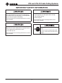
IMPORTANT SAFETY INFORMATION
Do not allow the rope to overlap on the capstan.
If the rope approaches the top of the angled part of
the capstan, relax the tailing force. If an overlap does
occur, shut off the puller immediately.
Failure to observe this warning could result in severe
injury or death.
Use this tool for manufacturer’s intended purpose
only. Do not use the cable puller as a hoist or winch.
• The cable puller cannot lower a load.
• The load may fall.
Failure to observe this warning could result in severe
injury or death.
Entanglement hazard:
• Do not operate the cable puller while wearing
loose-tting clothing.
• Retain long hair.
Failure to observe these warnings could result in
severe injury or death.
Wear eye protection when using this
tool.
Failure to wear eye protection could
result in severe eye injury from ying
debris.

UT4 and UT4-22 Cable Pulling Systems
Greenlee / A Textron Company 4455 Boeing Dr. • Rockford, IL 61109-2988 USA • 815-397-7070
6
Specifications
Weight .................................................................................................................. 175 lb
Motor
UT4 .............................................................................. 120 VAC, 50/60 Hz, 15 amps
UT4-22 ..........................................................................220 VAC, 50/60 Hz, 9 amps
Speed (high)
No load ........................................................................................................... 26 fpm
1000 lb ...........................................................................................................24 fpm
2000 lb ...........................................................................................................22 fpm
Speed (low)
No load ........................................................................................................... 13 fpm
2000 lb ...........................................................................................................12 fpm
4000 lb ...........................................................................................................11 fpm
Force (low speed) ..............................................3000 lb continuous (4000 intermittent)
Force (high speed) ...........................................................................1500 lb continuous
Pull Rope ................................................................... 9/16" double-braided composite
16,000-lb minimum break strength

UT4 and UT4-22 Cable Pulling Systems
Greenlee / A Textron Company 4455 Boeing Dr. • Rockford, IL 61109-2988 USA • 815-397-7070
7
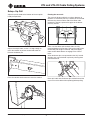
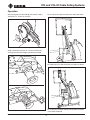
Initial Assembly
1. Insert the leg and wheel assembly tubes together
and secure with a short detent pin.
2. Lock the leg from pivoting by inserting the long
detent pin into one of the holes in the puller head
side plate.
3. Lay the puller down so the bar with the small
sheave is next to the ground and the main boom
is up in the air.
4. Slide the telescopic boom into the main boom and
secure with a long detent pin.
5. Slide the nose onto the telescopic boom and secure
with a long detent pin.

UT4 and UT4-22 Cable Pulling Systems
Greenlee / A Textron Company 4455 Boeing Dr. • Rockford, IL 61109-2988 USA • 815-397-7070
8
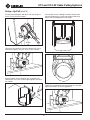
Assembly
To open from the folded position shown in Fig. 1, pull
the detent pin that locks the leg to the puller head and
let the wheel assembly drop to the oor as shown in
Fig. 2. Pull the pin that locks the wheels to the leg and
rotate the wheels as shown in Fig. 2. Replace the pin
that locks the wheels.
Lift up the puller head until you can insert the detent pin
in one of the four positioning holes as shown in Fig. 3.
The bottom hole shown often works well as it allows the
puller head to act as a counterbalance for easy trans-
port and conduit attachment.
Figure 1
Figure 2
Figure 3

UT4 and UT4-22 Cable Pulling Systems
Greenlee / A Textron Company 4455 Boeing Dr. • Rockford, IL 61109-2988 USA • 815-397-7070
9
Pivoting the nose unit:
The nose unit pivots and locks at various degrees of
rotation. It is locked in place by a detent pin set located
between the sheave and the end of the boom tube
receptacle. To pivot, squeeze the grips on the detent
pins fully inward.
Squeeze
Grips
Make sure the detent pins on both sides are fully
retracted before trying to pivot. Release the grips when
the desired pivot angle is reached, and pivot slightly
more to allow both detents to engage in the closest
holes.
When the detent pins are squeezed to the fully inward
position, they can be locked in place by twisting them
counterclockwise.
Twist to lock.
Never pull cable with the detent pins locked inward; the
nose unit must be locked from pivoting before pulling.
Adjust the puller head to the bottom of the two puller
head pivot positions.
Adjust telescopic boom so that it is long enough to
reach the conduit or pull out the desired cable tail.
Reinsert the detent pin.
Place the conduit attachment nose near the conduit.
Setup—Up Pull

UT4 and UT4-22 Cable Pulling Systems
Greenlee / A Textron Company 4455 Boeing Dr. • Rockford, IL 61109-2988 USA • 815-397-7070
10
Setup—Up Pull (cont’d)
If the conduit is free-standing or without threads, posi-
tion the clamping jaws so that the conduit will butt up
against the overhanging ats of the grips.
Tighten the knurled knob until the locking jaws are tight
against the conduit at all four grip points.
Locking
Pin
Pull the pivot locking pin and adjust the nose angle so
that it is in line with the conduit.
Unscrew the knurled nut until the clamping jaws can t
around the conduit. The jaws will t 2" to 4" conduit.
Butt the bottom of the clamping jaws up against the
conduit lock nut, or the lip of the grips against the top of
the conduit.

UT4 and UT4-22 Cable Pulling Systems
Greenlee / A Textron Company 4455 Boeing Dr. • Rockford, IL 61109-2988 USA • 815-397-7070
11
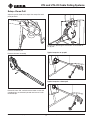
Setup—Down Pull
Adjust the puller head to the top of the two puller head
pivot positions.
Remove the detent pin.
Remove the nose assembly.
Rotate the nose 180° and reinsert the boom so that the
clamping jaws are oriented upwards and secure it with
the detent pin.
Continue by following the instructions as described for
an up-pull.
Typical setup for an up-pull.
Typical setup for a down-pull.

UT4 and UT4-22 Cable Pulling Systems
Greenlee / A Textron Company 4455 Boeing Dr. • Rockford, IL 61109-2988 USA • 815-397-7070
12
Setup—Floor Mount
Requires: A concrete oor with the following
characteristics:
• fully cured structural-type concrete
• minimum compressive strength of 211 kg/cm
2
(3000 psi)
• free of cracks, crumbling, or patchwork.
Follow all oor mounting instructions carefully.
• An improperly attached oor mount can come
loose and strike nearby personnel.
• Do not attach the oor mount to masonry, brick,
or cinder block. These materials will not hold the
anchors securely.
Failure to observe this warning could result in severe
injury or death.
1. Determine the best position for locating the oor
mount. Locate the oor mount:
• on a at section
• at least 152 mm (6") from edge of concrete
• as close to the conduit as possible to reduce the
amount of exposed rope under tension
• so that the pull rope will approach the puller’s
capstan at a 90° (± 5°) angle.
90°
at least
152 mm (6")
at least
152 mm (6")
at least
152 mm (6")
2. Set the oor mount in the desired location. Use the
oor mount as a template to drill four 5/8" holes at
least 152 mm (6") deep.
Note: Use a 5/8" carbide-tipped masonry bit
manufactured in accordance with ANSI standard
B94.12-77.
3. Vacuum the debris from the holes.
Installation
Greenlee recommends using Greenlee 35607 Wedge
Anchors. If another type of anchor is used, they must
have an ICBO (International Conference of Building
Ofcials) allowable tension and shear rating of 10.7 kN
(2400 lb) in 211 kg/cm
2
(3000 psi) concrete.
1. Assemble the nut and washer to the anchor so the
top of the nut is ush with the top of the anchor, as
shown.
Top of
Anchor
Nut
Washer
2. Insert the four anchors through the oor mount and
into the holes in the oor.
3. Hammer the anchors in until the washer is in rm
contact with the oor mount.
4. Expand the anchors by torquing the nuts to 122 to
128 Newton-meters (90 to 95 ft-lb).
If any of the four anchors spin before the minimum
torque is achieved, abandon the location and start
elsewhere. An improperly installed anchor can allow
the puller to break loose.
Failure to observe this warning could result in severe
injury or death.
5. Have the installation checked by a qualied
inspector.

UT4 and UT4-22 Cable Pulling Systems
Greenlee / A Textron Company 4455 Boeing Dr. • Rockford, IL 61109-2988 USA • 815-397-7070
13
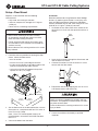
Operation
After shing the pull rope through the conduit, loop it
around the 12" sheave at the nose.
For an up-pull the rope should be just above the boom.
Wind it around the capstan in a clockwise direction,
starting at the beveled ange and working outward.
For a down-pull, the rope should be just below the boom.
For a side pull, the rope should end up above the boom
at the puller head end.

UT4 and UT4-22 Cable Pulling Systems
Greenlee / A Textron Company 4455 Boeing Dr. • Rockford, IL 61109-2988 USA • 815-397-7070
14
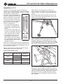
The lights will cycle through a power up sequence
with only the “0” light remaining lit. The default startup
speed is high. The high speed light will be lit. To change
the speed to low, double tap the
foot switch. The low speed light will
illuminate. Double tap the foot switch
again to change back to high speed.
After the foot switch is depressed,
the green light indicating 0 lb will be
lit. As the force climbs, an additional
light illuminates for every 500 lb
increase in pulling force.
• If the continuous operating limit
of the puller is exceeded in high
speed mode, the green lights start
to ash.
• If the continuous operating limit of
the puller is exceeded in low speed
mode, the yellow lights illuminate.
• The red light illuminates at 4000
lb to indicate that the maximum
operating limit of the puller has
been reached. The circuit breaker
(or current limiting) may shut down
the puller before or shortly after the
red light illuminates.
Make sure all nearby personnel are not standing in line
with or close to the pull rope. The right angle sheave on
the UT4 should be used to allow the operator to stand
off to the side as required.
Position yourself so that you can see the force gauge
indicator lights. Refer to the table below.
Force Gauge Indicator Lights
State of
Force Lights
Pulling Force (lb) Duty Cycle
Green
0–3000 (low)
Continuous
0–1500 (high)
Green ashing 2500–3000 (high) 15 ON/15 OFF
Yellow 3000–4000 (low)
15 ON/
change to low
Red Over 4000 STOP
Operation (cont’d)
When ready to start pulling cable, use only a few
wraps of rope on the capstan at rst. Using too many
wraps will reduce your ability to control the rope on the
capstan.
Use the right angle sheave to position yourself so you
are not in line with the high-tension rope in case it, the
cable, or the connector breaks.
Turn on the puller, using the foot switch and gradually
apply a tailing force to the free end of the rope. If the
tailing force becomes uncomfortably high, turn off the
puller and add another wrap. If the rope starts climbing
up the inside ange of the capstan, ease up in the tailing
force to allow it to settle down to the base diameter.
If it is continually climbing up the ange with minimal
tailing force, turn off the puller and remove a wrap. Do
not allow the rope to climb the ange so high that it runs
afoul with the puller head bolts. Applying any additional
tailing force over what is needed to prevent the rope
from slipping is causing additional friction and slowing
down the puller.
5000
4500
4000
3500
3000
2500
2000
1500
1000
0
500
PULL FORCE (LBS)
DOUBLE TAP
FOOT SWITCH
TO CHANGE
THE SPEED
LOW
SPEED
HIGH
SPEED

UT4 and UT4-22 Cable Pulling Systems
Greenlee / A Textron Company 4455 Boeing Dr. • Rockford, IL 61109-2988 USA • 815-397-7070
15
Maintenance
Shut off motor and unplug unit before dismantling or
servicing.
Failure to observe this warning will result in severe
injury or death.
Capstan
Wear
Check for wear on the outside of the capstan. If the
rope has worn a groove deeper than 0.10" on the 3"
diameter portion of the capstan, replace it.
Adjustment
If the capstan or puller frame is replaced, adjust the
axial free play to less than 1/32". Assemble the inner
thrust washers and capstan to the frame without the
chain. Attach with the bolt and retaining at washer.
If the capstan binds, add 52023123 shim washers one
at a time until it rotates freely. If it has more than 1/32"
of axial free play, add 50179160 ber washers to set the
free play at less than 1/32".
Motor
Commutator Brushes
Check the commutator brushes after every 40 hours of
operation. Remove the motor brush caps and brushes.
Measure the brush lengths. If length of either brush is
less than 3/8", replace both brushes.

UT4 and UT4-22 Cable Pulling Systems
Greenlee / A Textron Company 4455 Boeing Dr. • Rockford, IL 61109-2988 USA • 815-397-7070
16
Illustration and Parts List
1
2
3
4
5
5
6
6
2
1
3
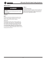
Nose Assembly 52059431
Key Part No. Description Qty
1 Nose weldment ....................................... 1
2 52059430 Arm weldment, right ...............................1
3 52059429 Arm, weldment, left .................................1
4 52025811 Cam ........................................................1
5 Screw kit .................................................1
6 Pin kit ......................................................1
Floor Mount 52044026
Key Part No. Description Qty
1 Floor mount weldment ............................ 1
2 50356070 Wedge anchor, .625 x 6 ..........................4
3 Decal, warning ........................................1

UT4 and UT4-22 Cable Pulling Systems
Greenlee / A Textron Company 4455 Boeing Dr. • Rockford, IL 61109-2988 USA • 815-397-7070
17
Illustration and Parts List
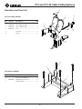
UT4
1 52059431 Nose assembly .......................................1
2 52059432 Pivot weldment .......................................1
3 52059427 Sheave assembly, 8"...............................1
4 52061297 Sleeve, short detent ................................ 1
5 52061296 Pin, short detent .....................................2
6 Roll pin, 1/4 x 3.00 .................................. 2
7 Grip, detent ............................................. 2
8 Spring, detent .........................................1
9 50251635 Pin ........................................................... 1
10 Roll pin, 3/16 x 1.51 ................................ 2
11 52044627 Pin kit ......................................................1
12 52025782 Tube, telescopic ......................................1
13 52042102 Boom weldment ......................................1
14 52026880 Leg weldment .........................................1
12
13
14
15
17
20
22
23
21
18
24
11
11
11
16
25
19
3
2
5
4
8
5
9
10
11
6
7
1
15 52026876 Leg weldment, telescoping .....................1
16 Hitch clip ................................................. 4
17 52026881 Foot weldment ........................................ 1
18 90553276 Wheel ......................................................2
19 Nut, hex ..................................................1
20 52026879 Bar, crash ................................................ 1
21 50353110 Sheave, right angle .................................1
22A 52027099 Gear motor, 115 V ...................................1
22B 52056984 Gear motor, 220 V ...................................1
23 52041840 Holder, document ...................................1
24 52044639 Shaft kit ...................................................1
25 90539214 Shoulder bolt ..........................................1
52049279 Motor cord ..............................................1
Key Part No. Description Qty Key Part No. Description Qty

UT4 and UT4-22 Cable Pulling Systems
Greenlee / A Textron Company 4455 Boeing Dr. • Rockford, IL 61109-2988 USA • 815-397-7070
18
Illustration and Parts List
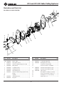
Gear Motor Assembly 52027099
1A 52027092 Motor, 115 V ...........................................1
1B 52056985 Motor, 220 V............................................1
2 52026783 Plate, puller mount .................................2
3 52044633 Gearcase with bearing (motor side) ....... 1
4 52044628 Idler gear kit ...........................................1
5 52044629 1st Reduction kit .................................... 1
6 52044630 2nd Reduction kit ...................................1
7 52044632 4th Reduction kit ....................................1
8 52044634 Gearcase with bearing (capstan side) ....1
9 Flange ....................................................1
10 Capstan ..................................................1
11 52044631 3rd Reduction kit ....................................1
12 52025761 Plug unit ................................................. 1
13 Screw, skt head cap, 5/16-24 x 3.5 ....... 8
14 52044637 Commutator brush kit .............................1
15 52044638 Bearing kit (not shown) ..........................1
16 Instruction manual holder .......................1
17 Screw, hex head, 1/2-20 UNF ................1
18 52063654 Armature and magnets (115 V) ...............1
52063655 Armature and magnets (230 V) ...............1
19 91865590 Tail housing .............................................1
20 Brush plate assembly (not shown) ..........1
21 Screw, skt head cap, 5/16-24 x 1 ........... 8
22 Dowel pin, ø1/4 x 1 (not shown) .............2
23 Washer, at, 1/2" .....................................1
19
3
4
5
6
7
8
9
10
11
12
13
21
14
16
17
18
2
1
23
Key Part No. Description Qty Key Part No. Description Qty

UT4 and UT4-22 Cable Pulling Systems
Greenlee / A Textron Company 4455 Boeing Dr. • Rockford, IL 61109-2988 USA • 815-397-7070
19
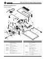
1 Electrical assembly .................................1
2 Housing, electrical box ...........................1
3 52061441 Overlay .................................................... 1
4 90541243 Bushing, strain relief ...............................1
5 Wire unit, 1/4" phono jack ......................1
6 50297082 Guard, switch ..........................................1
7 52040980 Switch, circuit breaker ............................1
8 52040979 Receptacle .............................................. 1
9 52045645 Wire unit, control board to
motor connector .....................................1
10 Wire unit, control board to
motor connector .....................................1
11 52045647 Wire unit, ground to motor connector ....1
12 Nut, 1/2 conduit lock ..............................1
13 Nut, hex ..................................................4
14 Screw, slotted machine ..........................2
15 52061142 Cover, electrical box ...............................1
16 50389416 Wire unit .................................................. 1
17 Pad, control box foot ..............................1
18 Screw, cap-button head,
#10-24 x .375 ..........................................6
19 Screw, self-tapping ................................. 6
20 Screw, 1/4-14 x .50 hex head ................. 4
21 52055558 Wire assembly.........................................1
22 52061607 Power cord unit.......................................1
23 Screw, slftpg, pan head, #6-32 x .375 .... 4
24 52059723 Foot switch, 16' ......................................1
Key Part No. Description Qty Key Part No. Description Qty
3
15
21
18
18
1
16
20
18
20
18
5
17
19
19
11
9
10
13
18
23
18
22
4
2
19
8
14
6
12
7
24
19
Illustration and Parts List
Control Box 52062552

4455 Boeing Drive • Rockford, IL 61109-2988 • USA • 815-397-7070
An ISO 9001 Company • Greenlee Textron Inc. is a subsidiary of Textron Inc.
USA Tel: 800-435-0786
Fax: 800-451-2632
Canada Tel: 800-435-0786
Fax: 800-524-2853
International Tel: +1-815-397-7070
Fax: +1-815-397-9247
www.greenlee.com
-
 1
1
-
 2
2
-
 3
3
-
 4
4
-
 5
5
-
 6
6
-
 7
7
-
 8
8
-
 9
9
-
 10
10
-
 11
11
-
 12
12
-
 13
13
-
 14
14
-
 15
15
-
 16
16
-
 17
17
-
 18
18
-
 19
19
-
 20
20


Greenlee UT4, UT4-22 Cable Pulling System AMJ, ABL User manual
- Category
- Toys
- Type
- User manual
Ask a question and I''ll find the answer in the document
Finding information in a document is now easier with AI
Related papers
-
Greenlee 854DX ELECTRIC CONDUIT BENDER User manual
-
Greenlee 658 Tray Type Sheave User manual
-
-
-
-
-
-
-
-
Other documents
-
 Big Red T32054 User manual
-
Toro Capstan Adaptor, Dingo Compact Utility Loader Installation guide
-
CHANCE Series 90 Capstan Hoist Owner's manual
-
Terex TM Series Tech Tips
-
 Power Team PH553C-E220 Operating Instructions Manual
-
Hubbell P308-0880 Owner's manual
-
Impact LSA-WMB4HD Operating instructions
-
 Tractel Tirfor/greifzug TU-8 Operating And Maintenance Instruction Manual
-
-
EDWARDS 1500 Series Door Holder Extension Rod Installation guide


