Toro Deck Footlift Assist Kit, TimeCutter Riding Mower Installation guide

Category
Lawnmowers
Type
Installation guide

Toro Deck Footlift Assist Kit, TimeCutter Riding Mower enhances your mowing experience by providing an easy and convenient way to raise and lower the mower deck. This kit is specifically designed for Toro TimeCutter Riding Mowers and can be installed with basic tools. Once installed, you can effortlessly operate the deck lift with your foot, freeing up your hands for better control of the mower. Enjoy a more comfortable and efficient mowing experience with the Toro Deck Footlift Assist Kit.

Toro Deck Footlift Assist Kit, TimeCutter Riding Mower enhances your mowing experience by providing an easy and convenient way to raise and lower the mower deck. This kit is specifically designed for Toro TimeCutter Riding Mowers and can be installed with basic tools. Once installed, you can effortlessly operate the deck lift with your foot, freeing up your hands for better control of the mower. Enjoy a more comfortable and efficient mowing experience with the Toro Deck Footlift Assist Kit.

FormNo.3436-785RevB
DeckFootliftAssistKit
TimeCutter
®
RidingMower
ModelNo.140-2059
InstallationInstructions
Installation
LooseParts
Usethechartbelowtoverifythatallpartshavebeenshipped.
ProcedureDescription
Qty.
Use
1
Nopartsrequired
Preparethemachine.
2
Nopartsrequired
RemovetheMyRideguard.
3
Nopartsrequired
Removetheliftlever.
Liftpedal
1
Footpeg1
Foot-liftplate
1
Carriagebolt(5/16x1-1/4inches)
2
Locknut(5/16inch)
2
Thrustwasher2
Spacer(3/8inch)
1
Spacer(5/16inch)
2
Link1
Carriagebolt(3/8x1inch)
1
Locknut(5/16inch)
2
Shoulderbolt(3/8x7/8inch)
2
Locknut(3/8inch)
3
Hex-headbolt(3/8x1inch)
1
Washer1
Nylonwasher1
4
Anti-seizepacket1
Installthefootpedal.
5
Nopartsrequired
Completethesetup.
©2020—TheToro®Company
8111LyndaleAvenueSouth
Bloomington,MN55420
Registeratwww.T oro.com.
OriginalInstructions(EN)
PrintedintheUSA
AllRightsReserved
*3436-785*
1
PreparingtheMachine
NoPartsRequired
Procedure
1.Parkthemachineonalevelsurface.
2.Disengagetheblade-controlswitch(PTO),move
themotion-controlleverstotheNEUTRAL-LOCK
position,andengagetheparkingbrake.
3.Shutofftheengine,removethekey,andwait
forallmovingpartstostopbeforeleavingthe
operatingposition.
4.Lowerthemowerdecktothelowestcutting
height.
2
RemovingtheMyRide
Guard
NoPartsRequired
Procedure
Note:Thisprocedureisonlyformachineswiththe
MyRideoption.
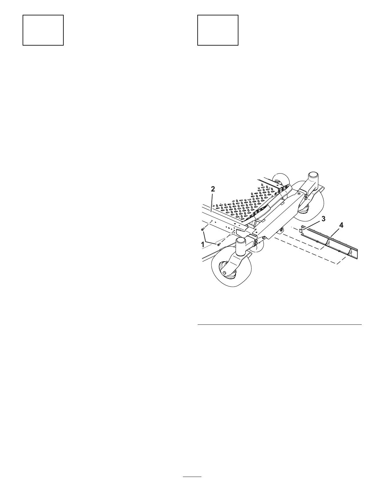
1.Removetheboltsfromtheframe(Figure1).
2.Slidetheguardtaboutoftheframebymoving
theguardforward(Figure1).
g308639
Figure1
1.Bolt
3.Guardtab
2.Frame
4.Guard
2
3
RemovingtheLiftLever
NoPartsRequired
Procedure
Removethehex-headbolt(5/16x1inch)andange
nut(5/16inch)securingtheliftlever(Figure2).
Retaintheliftleverforlaterinstallation.Youcan
discardthehex-headbolt(5/16x1inch)andange
nut(5/16inch).
g343672
Figure2
1.Hex-headbolt(5/16x1
inch)
3.Flangenut(5/16inch)
2.Liftlever
3
4
InstallingtheFootPedal
Partsneededforthisprocedure:
1
Liftpedal
1Footpeg
1
Foot-liftplate
2
Carriagebolt(5/16x1-1/4inches)
2
Locknut(5/16inch)
2Thrustwasher
1
Spacer(3/8inch)
2
Spacer(5/16inch)
1Link
1
Carriagebolt(3/8x1inch)
2
Locknut(5/16inch)
2
Shoulderbolt(3/8x7/8inch)
3
Locknut(3/8inch)
1
Hex-headbolt(3/8x1inch)
1Washer
1Nylonwasher
1Anti-seizepacket
4
Procedure
1.Securethefootpegtotheliftpedalusing1hex-headbolt(3/8x1inch)asshowninFigure3.
2.Securetheliftpedaltothelinkusing1shoulderbolt(3/8x7/8inch)and1locknut(3/8inch)asshown
inFigure3.
3.Securetheliftpedaltothesideoftheframeusing1shoulderbolt(3/8x7/8inch),1nylonwasher,1
washer,and1locknut(3/8inch)asshowninFigure3.
g343722
Figure3
1.Hex-headbolt(3/8x1inch)5.Locknut(3/8inch)
2.Footpeg
6.Shoulderbolt(3/8x7/8inch)
3.Liftpedal
7.Link
4.Washer8.Nylonwasher
5
4.Applyanti-seizetobothsidesofthe2thrustwashers.
5.Installthethrustwashersoneachsideoftheliftlever(Figure4).
Note:Installallthecarriageboltswiththeboltheadsontheinsideofthemachine.
6.Securethefoot-liftplatetothelinkusing1carriagebolt(3/8x1inch),2carriagebolts(5/16x1-1/4
inches),1spacer(3/8inch),2spacers(5/16inch),1locknut(3/8inch),and2locknuts(5/16inch)
asshowninFigure4.
g343743
Figure4
1.Locknut(3/8inch)6.Liftlever
2.Foot-liftplate
7.Thrustwashers
3.Spacer(3/8inch)8.Spacers(5/16inch)
4.Carriagebolt(3/8x1inch)9.Locknuts(5/16inch)
5.Carriagebolts(5/16x1-1/4inches)
6
5
CompletingtheSetup
NoPartsRequired
Procedure
1.FormachineswiththeMyRideSuspension
System,slidetheguardtabintotheframe
(Figure1).
2.FormachineswiththeMyRideSuspension
System,installtheboltsintotheframeand
guard(Figure1).
3.Usetheheight-of-cutleverandfootpedalto
raiseandlowerthemowerdeck,checktoseeif
thereisanybinding.Ifso,checktheinstallation.
4.Adjustasnecessary.
7
1 / 1

Toro Deck Footlift Assist Kit, TimeCutter Riding Mower Installation guide

Category
Lawnmowers
Type
Installation guide

Toro Deck Footlift Assist Kit, TimeCutter Riding Mower enhances your mowing experience by providing an easy and convenient way to raise and lower the mower deck. This kit is specifically designed for Toro TimeCutter Riding Mowers and can be installed with basic tools. Once installed, you can effortlessly operate the deck lift with your foot, freeing up your hands for better control of the mower. Enjoy a more comfortable and efficient mowing experience with the Toro Deck Footlift Assist Kit.

Ask a question and I''ll find the answer in the document

Finding information in a document is now easier with AI

Ask the document