
www.furuno.com
NAVpilot-700/711
VOLVO IF KIT FAP-6300
INSTALLATION INSTRUCTIONS
This information provides the instructions for the installation of the VOLVO IF kit. This kit enables
the NAVpilot-700/711 to automatically steer a VOLVO IPS drive equipped vessel whose length is
between 35 and 80 ft.
For the operation and installation of the autopilot, see the operator’s manual (OME-72720) and
installation manual (IME-72720).
Please read these safety instructions before you install or operate the equipment.
Do not use the autopilot in the
following situations:
- Cruising speed is more than 40 kn
- Harbor entrance or narrow channel
- Where vessels change course often,
such as a cape or small island
- Poor visibility areas because of the
fog or rain, etc.
- When the vessel is stopped
IF-700IPS 0.30 m 0.30 m
Do not open the equipment unless
you are well familiar with electrical
circuits.
Only qualified personnel should work
inside the equipment.
WARNING
WARNING
CAUTION
Do not lock the helm when the
autopilot controls the vessel.
Malfunction or accident can result.
Do not speed up suddenly when the
autopilot controls the vessel.
Do not raise the speed to 30-40 kn
within 30 seconds. The autopilot can
not calculate parameters under those
conditions. Malfunction or accident can
result.
When an alarm sounds, switch the
steering mode to the STBY mode
and then control the vessel with the
helm.
Malfunction or accident can result if the
vessel is steered automatically.
For the heading sensor, use the
PG-700.
Use the rate gyro hybrid sensor (PG-700)
for the heading sensor. Install the
PG-700 away from metallic objects,
radiotelephone, and the antenna of a
radiotelephone. Malfunction or accident
can result if the sensor is too close to
those objects.
Do not input the heading data (output
from the autopilot) to the radar, etc.
The heading data output from the
autopilot is delayed for max 1 second
over the input data.
Follow the compass safe distances to
prevent interference to a magnetic
compass.
Standard
Compass
Steering
Compass

2
1. Materials
VOLVO IF Kit (Type: FAP-6300, Code No.: 000-022-971)
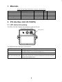
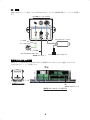
2. IPS Interface Unit (IF-700IPS)
2.1 LED status and meaning
The LED on the IPS interface unit indicates the status of the unit.
The LED status and meaning are shown below.
Name Type Code No. Qty Remarks
IPS Interface Unit IF-700IPS - 1
VOLVO IPS Gateway AUTOPILOT-GATEWAY - 1
Cable Assy. MJ-A7SPF0005-020C 000-159-699-10 1 2 m
Self-tapping Screw 4x16 SUS304 000-162-605-10 4
Fuse FGMB 125V 1A PBF 000-157-478-10 1 Spare parts
LED Lamp Status Status/Action
Off The IPS interface unit is OFF. The unit is powered by the processor
unit (FAP-7002). Turn on the processor unit.
Flashes The IPS interface unit operates normally.
Flashes twice, and then
goes off for two seconds
Communication error between the VOLVO IPS gateway and IPS in-
terface unit. Check the connection between the VOLVO IPS gate-
way and IPS interface unit.
LED (green)
IPS interface unit IF-700IPS

3
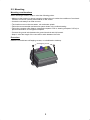
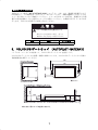
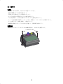
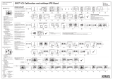
2.2 Mounting
Mounting considerations
When selecting a location, keep in mind the following points.
• Make sure the location is strong enough to support the unit under the conditions of continued
vibration and shock normally encountered on the vessel.
• Locate the unit away from heat sources.
• The location must not be near water, rain and water splash.
• Follow the recommended maintenance space shown in the outline drawing.
• Follow the compass safe distance (standard compass: 0.30 m, steering compass: 0.30 m) to
prevent interference to a magnetic compass.
• Connect the ground wire between the ground terminal and ship’s earth.
• Keep in mind the length of the connection cable between the units.
Procedure
Install the unit with two self-tapping screws, on a bulkhead or desktop.
Self-tapping screw

4
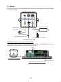
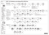
2.3 Wiring
Connect the cable assy. (MJ-A7SPF0005-020C) and VOLVO IPS gateway to the IPS interface
unit as shown below.
Connection with the processor unit FAP-7002
Connect the cable assy. (MJ-A7SPF0005-020C) to TB1 (power) and TB7 (NMEA0183 port 2) of
the processor unit as shown in the procedure which follows.
Ground wire
(IV-1.25sq.)
Cable Assy.
(MJ-A7SPF0005-020C, 2m)
To processor unit FAP-7002
To VOLVO Penta EVC system
VOLVO IPS gateway
IPS interface unit IF-700IPS
TB1
䋨
Power
䋩
Cable entrance of the processor unit
㪂㩷㩷㩷㩷㪄
㪂㩷㩷㩷㩷㪄
㪂㩷㩷㩷㩷㪄
TB7
䋨
NMEA 0183 port 2
䋩
Processor unit FAP-7002

5
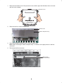
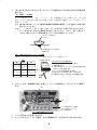
1. Remove the outside cover of the processor unit; hold the right and left sides of the cover and
pull the cover outward.
2. Remove the four screws circled below.
3. Remove the cable clamp/fan assy. from the shield cover.
Note: When removing the cable clamp/fan assy., be careful not to apply tension to the fan
connector.
4. Disconnect the fan connector.
Outside cover
Cable clamp/fan assy.
Shield cover
Disconnect
this connector.

6
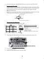
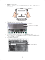
5. Connect the cable assy. (MJ-A7SPF0005-020C) to the connector blocks TB1 and TB7.
Connection with TB1 (power)
Clamp the power line of the cable assy. and power cable of processor unit with the crimping
terminal, and then connect the + line (red) and - line (black) to the TB1 of the processor unit.
For the crimping terminal, use rod terminals or plate shape pre-insulation terminals.
Note1: Do not twist cores.
Note2: The + line (red) has a fuse holder. To prevent the detachment of the fuse, make a loop
in the power line of the cable assy. and then fix the lines as shown below.
Connection with TB7 (NMEA port 2)
Connect the signal lines of the cable assy. to TB7.
6. Fix the cable assy. to the cable clamp with a cable tie (supplied with processor unit).
7. Connect the fan connector.
8. Reattach the cable clamp/fan assy. and outside cover.
1 A fuse holder
(+ line, red)
Fix the lines with a cable tie.
Connector block
Push
Twist
cores.
6 mm
How to put wire into connector block
1. Make length of cores 6 mm.
2. Twist cores.
3. Push spring-loaded catch with slotted-head
screwdriver.
4. Insert core into hole.
5. Release screwdriver.
6. Pull wire to confirm it is securely inserted.
1234
5
5
ColorPin No.
Green
1
2
3
4
5
Yellow
White
Blue
Drain
TB7
Signal
TD_A
TD_B
RD_H
RD_C
Shield
Wind the copper tape around
the cable assy., and then fix to
the cable clamp with a cable tie.
Example: After connecting the cable assy.
TB7
TB1

7
Fuse replacement
The fuse in the fuse holder on the + line (red) of the cable assy. (MJ-A7SPF0005-020C) protects
the IPS interface unit from overcurrent and equipment fault. If you can not turn on the power, check
if the fuse has blown. If the fuse has blown, find the reason before you replace the fuse. If the fuse
blows again after the replacement, contact your dealer for advice.
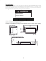
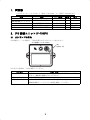
VOLVO IPS Gateway (AUTOPILOT GATEWAY)
Install the unit with two self-tapping screws.
For details of the installation and wiring, see the installation manual of the VOLVO IPS gateway.
Name Type Code No.
Fuse FGMB 125V 1A PBF 000-157-478-10
WARNING
Use the proper fuse.
Use of a wrong fuse can result in fire and
damage the equipment.
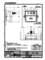
: Minimum service clearance.
Unit 䋨mm䋩
130
116
56
10
250
60
20
20.5
5.5
10

8
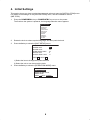
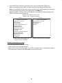
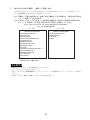
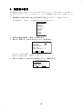
4. Initial Settings
This section shows you how to select language and units and open the [INSTALLATION] menu.
For details of the settings on the [INSTALLATION] menu, see the installation manual
(IME-72720).
1. Press the POWER/BRILL key or POWER/STBY key to turn on the power.
The first time the system is powered, the language selection menu appears.
2. Rotate the knob to select required language, and then push the knob.
3. Press the X key to show the [UNIT SETUP] menu.
1) Select the item to change then push the knob.
2) Select the unit to use then push the knob.
4. Press the X key to show the [OPERATION MODE] menu.
㪜㪥㪞㪣㪠㪪㪟㩿㪬㪪㪘㪀
㪜㪥㪞㪣㪠㪪㪟
㪝㪩㪘㪥㪚㪘㪠㪪
㪜㪪㪧㪘㪥㪦㪣
㪧㪦㪩㪫㪬㪞㪬㪜㪪
㪛㪜㪬㪫㪪㪚㪟㪜
㪠㪫㪘㪣㪠㪘㪥㪦
㪥㪦㪩㪪㪢
㪛㪘㪥㪪㪢㪜
㪪㪭㪜㪥㪪㪢㪘
㪪㪬㪦㪤㪠
UNITS SETUP
SPEED UNIT: kn
RANGE UNIT: nm
WIND SPEED UNIT: kn
DEPTH UNIT: ft
WATER TEMP UNIT: °F
PREV NEXT
OPERATION MODE
INSTALLATION
DEMO SLIDE SHOW
SIMULATOR
PREV NEXT ENTER

9
5. Select [INSTALLATION] then push the knob to show the [INSTALLATION] menu.
See the installation manual (IME-72720) for how to set the [INSTALLATION] menu.
Note1: The [INSTALLATION] menu can be opened from the STBY display by pressing the
knob three times while pressing and holding down the MENU key.
Note2: Set [BOAT TYPE] to [VOLVO EVC BOAT] on the [SHIP’S CHARACTERISTICS]
menu to use the VOLVO interface kit.
Check points before cruising
Check the following points before cruising.
• Confirm that no error message appears.
• When the IPS drive controls the rudder, the OVRD (override) mode is automatically enabled.
• The rudder turns according to the W and X key in the AUTO mode.
INSTALLATION MENU
LANGUAGE: ENGLISH
UNITS SETUP
DISPLAY SETUP
SHIP’S CHARACTERISTICS
CAN BUS SETUP
NMEA0183 SETUP
SENSOR SELECTION
UNIVERSAL PORT
SEA TRIAL
COMPASS CALIBRATION: NO
1
,
2
DATA CALIBRATION
PARAMETER SETUP
AUTO OPTION
NAV OPTION
INSTALLATION MENU
FISH HUNTER OPTION
SYSTEM SETUP
RC SETUP
ALARM
Page 1 Page 2
1
: NO is replaced with DONE when
respective setup is completed.
NAVpilot-700 INSTALLATION menu
( BOAT TYPE VOLVO EVC BOAT )
2
: Shown when PG-700 is connected.

10
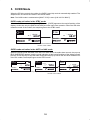
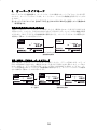
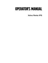
5. OVRD Mode
When the IPS drive controls the rudder, the OVRD (override) mode is automatically enabled. The
autopilot can not control the vessel in the OVRD mode.
Note: The OVRD mode is enabled when [BOAT TYPE] is set to [VOLVO EVC BOAT].
OVRD mode activation in the STBY mode
When the OVRD mode activates in the STBY mode, [OVRD] appears at the top-left position of the
display. At this time only the [INSTALLATION] and user menus are operative. When the IPS drive
releases control of the rudder, the autopilot goes to the STBY mode.
OVRD mode activation in the AUTO or NAV mode
When the OVRD mode activates in the AUTO or NAV mode, the audio alarm sounds, the pop-up
[EVC OVERRIDE] appears, and the mode indication at the top-left position of the display shows
[OVRD]. Press any key to stop the alarm and erase the pop-up. When the IPS drive releases con-
trol of the rudder, the autopilot goes to the STBY mode.
A
UTO
䍽
65
SETCSE
HDG
M
68.0䍽
䍽
DEVIATION
3䍽
䍽
20 10 5 5 10 20
㪦
㪭㪩㪛
㪩㪬㪛㪛㪜㪩
㵥
䍽
65
SETCSE
HDG
M
68.0䍽
䍽
DEVIATION
3䍽
䍽
20 10 5 5 10 20
㪩㪬㪛㪛㪜㪩
㵥
㪪
㪫㪙㪰
When the IPS drive releases
control of the rudder.
A
UTO
䍽
65
SETCSE
HDG
M
68.0䍽
䍽
DEVIATION
3䍽
䍽
20 10 5 510 20
㪦
㪭㪩㪛
㪩㪬㪛㪛㪜㪩
㵥
㪜㪭㪚㩷㪦㪭㪜㪩㪩㪠㪛㪜
A
UTO
䍽
65
SETCSE
HDG
M
68.0䍽
䍽
DEVIATION
3䍽
䍽
20 10 5 5 10 20
㪦
㪭㪩㪛
㪩㪬㪛㪛㪜㪩
㵥
䍽
65
SETCSE
HDG
M
68.0䍽
䍽
DEVIATION
3䍽
䍽
20 10 5 5 10 20
㪩㪬㪛㪛㪜㪩
㵥
㪪
㪫㪙㪰
Press any key.
When the IPS drive releases
control of the rudder

11
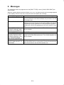
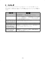
6. Messages
The massages which may appear when the [BOAT TYPE] is set to [VOLVO EVC BOAT] are
shown below.
When the system detects an alarm violation, error, etc., the alarm sounds and a message appears
on the display. Press the any key to stop the alarm and delete the message.
Message Status/Action
EVC INTERFACE ERROR Communication error between the processor unit and IPS inter-
face unit. Check the connection between the processor unit and
IPS interface unit.
NO CONTACT WITH EVC. Communication error between the VOLVO IPS gateway and IPS
interface unit occurs. Check the connection between the VOLVO
IPS gateway and IPS interface unit. Also check the connection
between the VOLVO IPS gateway and VOLVO Penta EVC sys-
tem.
EVC INTERFACE FAIL.
PLEASE TURN OFF AND
CHECK EVC INTERFACE.
System error of the IPS interface unit. Turn off the autopilot, con-
tact your dealer.
EVC OVERRIDE The OVRD mode is enabled.
EVC INTERFACE HAS
FAILED STARTUP TEST.
PLEASE CONTACT A LO-
CAL FURUNO REPRE-
SENTATIVE FOR REPAIR.
This message appears for the result of the startup test.
System error of the IPS interface unit. Turn off the autopilot, con-
tact your dealer.
NO CONNECT EVC INTER
FACE. PUSH ANY KEY TO
CONTINUE.
This message appears for the result of the startup test.
The IPS interface unit is not connected. Check the connection be-
tween the processor unit and IPS interface unit.

/CT
;0+5*+;#/#
D-1

$
#
&
%
0#/'
ฬ⒓
6+6.'
MI
/#55
&9) 0Q
5%#.'
#22418'&
%*'%-'&
&4#90
4'(0Q
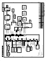
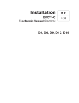
+06'4%100'%6+10 &+#)4#/
⋧⚿✢࿑
ࠝ࠻ࡄࠗࡠ࠶࠻
#7612+.16
0#8RKNQV
126+10
5*+2;#4& 5722.;
016'
㧖㧞㧕ࠝࡊ࡚ࠪࡦޕ
㧖㧝㧕ㅧ⦁ᚲᚻ㈩ޕ
ᵈ⸥
㧖㧟㧕ࠤࡉ࡞㐳ߐߦࠃࠅ⧌✢ߩᄥߐࠍᄌᦝߔࠆޕ
%*#0)' 6*' %14' 5+<' #%%14&+0) 61 %#$.' .'0)6*
6;#/#5#-+
*/#-+
5*+'.&
)0&
9*6
$.7
;'.
)40
4'&
$.-
ࠪࡠ
ࠕࠝ
ࠠ
㩚㩎㩨㩢
ࠕࠞ
ࠢࡠ
)0&
%10641. #
5*+'.&
)0&
9*6
$.7
;'.
)40
4'&
$.-
ࠪࡠ
ࠕࠝ
ࠠ
㩚㩎㩨㩢
ࠕࠞ
ࠢࡠ
%10641. $
,
5*+'.&
)0&
$.7
;'.
)40
ࠕࠝ
ࠠ
㩚㩎㩨㩢
4'&ࠕࠞ
࠴ࡖ $40
4'/2
4'/5+)
4'/0
4'/59
4475+)
447A5+)
5*+'.&
)40㩚㩎㩨㩢
;'.ࠠ
ࠢࡠ
ࠪࡠ 9*6
$.-
447
,
,
%10641. 70+6
ᠲㇱ
,
,
)0&
O (#2
4'/16' %10641..'4
㆙㓒▤ེ
47&&'4 4'('4'0%'
ㅊᓥ⊒ାེ
70+6 (#2
ห
&+661
6'4/+0#614
⚳┵ེ
,
%10641. 70+6
ᠲㇱ
OǾ
5*+'.&
)0&
4'/16' %10641..'4
(#2
㆙㓒▤ེ
4'/16' %10641..'4
㆙㓒▤ེ
4'/16' %10641..'4
㆙㓒▤ེ
(#2 (#2
ᠲㇱᠲㇱ %10641. 70+6%10641. 70+6
+8US
+8US
+8US
4'/2
4'/5+)
4'/0
4'/59
(#2 (#2
,
(#2
(#2
6$
8&%
219'4
%#0 DWU
6$
5*+'.&
$&#((/
219'4A59
%#0A*
%#0A.
8A2
$&#((/
.4
OǾ
$&#((/
$&#((/.4OǾ
$&#((/.4OǾ
6$
6$
0'6A5
0'6A%
0'6A*
0'6A.
0'6 219'4
6$
0'6A5
0'6A%
5*+'.&
+8US
8$75
&A2
&A0
)0&
75$
8$75
&A2
&A0
)0&
75$
75$ %#$.'
6$
4'/
447A294
)0&
)0&
8A2
219'4A59
%#0A*
%#0A.
4'/16' %10641..'4
㆙㓒▤ེ
(#2
4'/16' %10641..'4
(#2
㆙㓒▤ེ
/,#52(OǾ
/,#52(
,
/,#52(
4'/2
4'/5+)
4'/0
4'/59
4'/%1/
0%
0%
0%
0%
()
4'/2
4'/5+)
4'/0
4'/59
4'/%1/
0%
0%
0%
0%
()
ࠕࠝ
ࠠ
㩚㩎㩨㩢
࠴ࡖ
ࠕࠞ
$.7
;'.
)40
4'&
$40
294A59A*
294A59A%
%#0A*
%#0A.
8
5*+'.&
)0&
294A59A*
294A59A%
%#0A*
%#0A.
8
5*+'.&
)0&
294A59A*
294A59A%
%#0A*
%#0A.
8
5*+'.&
)0&
294A59A*
294A59A%
%#0A*
%#0A.
8
5*+'.&
)0&
294A59A*
294A59A%
%#0A*
%#0A.
8
5*+'.&
)0&
294A59A*
294A59A%
%#0A*
%#0A.
8
5*+'.&
(#2
&+564+$7614
ಽ㈩ེ
,
,
/,#52(
/,#52(
,
ห
&+661
O
2%
ࡄ࠰ࠦࡦ
ࡔࡦ࠹࠽ࡦࠬ↪
(14 /#+06'0#0%' 10.;
%10641. 70+6
ᠲㇱ
(#2
(#2
,70%6+10 $1:
ࠤࡉ࡞ᑧ㐳
࡙࠾࠶࠻
$&#((/
,
$&#(#(.4
OǾ
$&#(#(.4
OǾ
㩒㨹㩎㩦㨺㩂㩍㩨㩔㩨㨼㩇
0'6914- &'8+%'
6$
㧔ㆬᛯ㧕
㧔5'.'%6㧕
)0&
51.$/1614
51.#/1614
6$
51.#
51.$
51.%1/
51.'01+& 8#.8'
㔚⏛ᑯ
4'8'45+$.' 27/2
ࡃࠪࡉ࡞ࡐࡦࡊ
/1614#
/1614$
241%'5514 70+6
ᓮㇱ
(#2
6$
$%A219'4
$%
5*+'.&
/1614
/1614
$;2#55%.76%*
$;2#55%.76%*
$%
*;&4#7.+% .+0'4
&4+8'
ࠢ࠶࠴
/161451.
5*+'.&
6&#
6&$
4&*
4&%
2
2
0/'# 2146
6$
5*+'.&
6$
)'0'4#. 176
176A01
%1/
176A0%
176A01
%1/
176A0%
4'.#; %106#%6 /#:#
ᄖㇱࠕࡓ
':6'40#. #.#4/
ᄖㇱࠕࡓ
':6'40#. #.#4/
ାภߩ⒳㘃ߦࠃࠅធ⛯ࠍㆬᛯߔࠆ
%100'%6+10 5'.'%6'& $; 5+)0#. /1&'
)'0'4#. +0
6$
59A8
59A+0
59A)0&
59A8
59A+0
59A)0&
ࠗࡌࡦ࠻ࠬࠗ࠶࠴
'8'06 59+6%*
*'./ 5'0514
*'./ 5'0514
*'./ 5'0514A5+)
*'./ 5'0514
*'./ 5'0514A5+)
*'./ 5'0514
&2;/#:#
&2;
&2;
#66#%*'&
/1614#
/1614$
ࡄࡢࠕࠪࠬ࠻ࠪࠬ࠹ࡓ
#%%756''4 (25
$40࠴ࡖ
ࠢࡠ
ࠕࠝ
$.-
$.7
$40࠴ࡖ
ࠢࡠ
ࠕࠝ
$.-
$.7
ࠢࡠ $.-
ࠕࠞ 4'&
%#$.'O
0%
5*+'.&
6:&*
6:&%
4:&*
4:&%
⥶ᴺⵝ⟎
0#8 '37+2/'06
߹ߚߪ 14
*'#&+0) 5'05140/'#
/,#52(OǾ
;'.
)40
ࠠ
㩚㩎㩨㩢
9*6ࠪࡠ
ࠢࡠ $.-
㩗㩍㩨㨲㩧㩂㩨㩈㩧㩅㨺
5*+'.&
6$
6&#
6&$
4&*
4&%
2
0/'# 2146
2
+(+25
+25ធ⛯࡙࠾࠶࠻
+25 +06'4(#%' 70+6
+8US
#
;'.
)40
ࠠ
㩚㩎㩨㩢
9*6ࠪࡠ
ࠕࠝ $.7
ࠢࡠ $.-
ࠕࠞ 4'&
/$((/O
%$$((/O
ࠕࠞ 4'&
ࠢࡠ $.-
ࠪࡠ 9*6
ࠕࠝ $.7
1// .
6'4/+0#614
⚳┵ེ
219'4 5722.;
8&%
8%6(Z%
/CT
/CT
%% ,
/2;
/,#52(%O
81.81 +06'4(#%' -+6
81.81ࠗࡦ࠲ࡈࠚࠗࠬࠠ࠶࠻
(#2
&2;
8&%
62;
O
81.81 +25 )#6'9#;
#7612+.16 )#6'9#;
81.81 +25ࠥ࠻࠙ࠚࠗ
81.81 +25
/CT;0+5*+;#/#
Yoshihir
o
Nishiya
ma
:Yoshihiro NishiyamD
DN:cn=Yoshihiro Nishiyama, c=JP - , o=FURUNO
ELECTRIC Co., Ltd., ou=Technical Documentation
Section, [email protected]S
:2013.03.19 08:53:50 +09'00
S-1

11
㪍㪅㩷 䊜 䉾 䉶䊷䉳
㪲㪙㪦㪘㪫㩷㪫㪰㪧㪜㪴 䈏 㪲㪭㪦㪣㪭㪦㩷㪜㪭㪚㩷㪙㪦㪘㪫㪴 䈱 䈫 䈐 䈮⊒↢䈜 䉎 䊜 䉾 䉶䊷䉳 䉕ਅ䈮⸥タ 䈚 䈩䈇䉁䈜䇯
䉝䊤䊷䊛䉇䉣䊤䊷䈏⊒↢䈚䈢䈫 䈐䈲䇮 䉝䊤䊷䊛㖸䈏㡆䉍䇮 䊘䉾䊒䉝䉾䊒䊜 䉾䉶䊷䉳䈏↹㕙䈮
␜䈘䉏䉁䈜䇯 䈇䈝䉏䈎䈱䉨䊷䉕䈚䈩䇮 䉝䊤䊷䊛㖸䈍䉋䈶䊘䉾䊒䉝䉾䊒䊜 䉾䉶䊷䉳䈏ᶖ䈚䈩
䈒䈣䈘䈇䇯
䊜 䉾 䉶䊷䉳 ⁁ᘒ 㪆 ಣℂ
EVC INTERFACE ERROR
ᓮㇱ -IPS ធ⛯࡙࠾࠶࠻㑆ߩㅢାਇ⦟߇⊒↢ߒߡ߹ߔޕ
ᓮㇱ -IPS ធ⛯࡙࠾࠶࠻㑆ߩធ⛯ࠍ⏕ߒߡߊߛߐޕ
NO CONTACT WITH EVC.
IPSធ⛯࡙࠾࠶࠻-VOLVO IPSࠥ࠻࠙ࠚࠗ㑆ߩㅢାਇ⦟߇⊒↢
ߒߡ߹ߔޕIPS ធ⛯࡙࠾࠶࠻ -VOLVO IPS ࠥ࠻࠙ࠚࠗ㑆ߩ
ធ⛯ޔ߅ࠃ߮ VOLVO IPS ࠥ࠻࠙ࠚࠗ -VOLVO Penta EVC ࠪ
ࠬ࠹ࡓ㑆ߩធ⛯ࠍ⏕ߒߡߊߛߐޕ
EVC INTERFACE FAIL.
PLEASE TURN OFF AND
CHECK EVC INTERFACE.
IPS ធ⛯࡙࠾࠶࠻ߦ⇣Ᏹ߇⊒↢ߒߡ߹ߔޕᧄᯏߩ㔚Ḯࠍಾࠅޔ
ᒰ␠߹ߚߪઍℂᐫߦ߅วࠊߖߊߛߐޕ
EVC OVERRIDE
ࠝࡃࠗ࠼ࡕ࠼ߦ⒖ⴕߒߚߎߣࠍ⍮ࠄߖࠆㅢ⍮ޕ
EVC INTERFACE HAS
FAILED STARTUP TEST.
PLEASE CONTACT A LO-
CAL FURUNO REPRE-
SENTATIVE FOR REPAIR
േᤨߩࠬ࠲࠻ࠕ࠶ࡊ࠹ࠬ࠻ߩ⚿ᨐߣߒߡ␜ߐࠇ߹ߔޕ
IPS ធ⛯࡙࠾࠶࠻ߦ⇣Ᏹ߇⊒↢ߒߡ߹ߔޕᧄᯏߩ㔚Ḯࠍಾࠅޔ
ᒰ␠߹ߚߪઍℂᐫߦ߅วࠊߖߊߛߐޕ
NO CONNECT EVC IN-
TERFACE. PUSH ANY
KEY TO CONTINUE
േᤨߩࠬ࠲࠻ࠕ࠶ࡊ࠹ࠬ࠻ߩ⚿ᨐߣߒߡ␜ߐࠇ߹ߔޕ
IPS ធ⛯࡙࠾࠶࠻߇ធ⛯ߐࠇߡ߹ߖࠎޕᓮㇱ -IPS ធ⛯࡙
࠾࠶࠻㑆ߩធ⛯ࠍ⏕ߒߡߊߛߐޕ

10
㪌㪅㩷 䉥䊷䊋䊷䊤 䉟 䊄 䊝䊷 䊄
㪠㪧㪪 䊄 䊤 䉟 䊑䈮 䉋 䉎 ⥽ᯏᓮਛ䇮 䉥䊷 䊃 䊌 䉟 䊨 䉾 䊃 䈲⥄േ⊛䈮䉥䊷䊋䊷 䊤 䉟 䊄 䊝䊷 䊄 䈮ಾ 䉍 ᦧ
䉒 䉍 䉁䈜䇯 䉥䊷䊋䊷䊤 䉟 䊄 䊝䊷 䊄 ਛ䈲䇮 䉥䊷 䊃 䊌䉟 䊨 䉾 䊃 䈮䉋 䉎⥄േᠲ⥽䉕↪䈜䉎 䈖 䈫 䈲䈪
䈐䉁䈞䉖䇯
ᵈ㧕ࠝࡃࠗ࠼ࡕ࠼ߪޔ[BOAT TYPE] ࠍ [VOLVO EVC BOAT] ࠍ⸳ቯߒߡࠆ႐วߩߺ
↪น⢻ߢߔޕ
ᚻേ䊝䊷 䊄 ᤨ䈱䉥䊷䊋䊷 䊤 䉟 䊄 䊝䊷 䊄
ᚻേ䊝䊷 䊄 ᤨ䈮䉥䊷䊋䊷 䊤 䉟 䊄 䊝䊷 䊄 䈮⒖ⴕ 䈚 䈢 䈫 䈐 䇮 ↹㕙Ꮐ䈱䊝䊷 䊄 ␜䈏 㪲㪦㪭㪩㪛㪴 䈮ಾ
䉍 ᦧ䉒 䉍 䉁䈜䇯 䈖 䈱 䈫 䈐 䇮 㪲㪠㪥㪪㪫㪘㪣㪣㪘㪫㪠㪦㪥㩷㪤㪜㪥㪬㪴 䉁 䈢䈲䊡䊷䉱䊷 䊜 䊆 䊠 䊷એᄖ䈱ᯏ⢻䈲↪
䈪 䈐 䉁䈞䉖䇯 㪠㪧㪪 䊄 䊤 䉟 䊑䈮 䉋 䉎 ⥽ᯏᓮ䈏⸃㒰 䈘 䉏 䉎 䈫 䇮 䉥䊷䊋䊷䊤 䉟 䊄 䊝䊷 䊄 䈲⸃㒰 䈘 䉏
⥄േ⊛䈮ᚻേ䊝䊷䊄 䈮ಾ 䉍 ᦧ䉒 䉍 䉁䈜䇯
⥄േ 㪆 ⥶ᴺ䊝䊷 䊄 ᤨ䈱䉥䊷䊋䊷 䊤 䉟 䊄 䊝䊷 䊄
⥄േ 㪆 ⥶ᴺ䊝䊷 䊄 ᤨ䈮䉥䊷䊋䊷 䊤 䉟 䊄 䊝䊷 䊄 䈮⒖ⴕ 䈚 䈢 䈫 䈐 䇮 䉝 䊤 䊷䊛㖸䈍 䉋 䈶䊘 䉾 䊒䉝 䉾 䊒
㪲㪜㪭㪚㩷㪦㪭㪜㪩㪩㪠㪛㪜㪴 䈏␜ 䈘 䉏䇮 ↹㕙Ꮐ䈱䊝䊷 䊄 ␜䈏 㪲㪦㪭㪩㪛㪴 䈮ಾ 䉍 ᦧ䉒 䉍 䉁䈜䇯 䈇䈝䉏䈎
䈱䉨䊷䉕䈚䈩䇮 䉝 䊤䊷䊛㖸䈍䉋䈶䊘䉾䊒䉝䉾䊒 㪲㪜㪭㪚㩷㪦㪭㪜㪩㪩㪠㪛㪜㪴 䉕ᶖ䈚䈩 䈒 䈣䈘䈇䇯 䉝
䊤 䊷䊛䈱⍮ᓟ䈮 㪠㪧㪪 䊄 䊤 䉟 䊑䈮 䉋 䉎⥽ᯏᓮ䈏⸃㒰 䈘 䉏 䉎 䈫 䇮 䉥䊷䊋䊷 䊤 䉟 䊄 䊝䊷 䊄 䈲⸃㒰
䈘䉏⥄േ⊛䈮ᚻേ䊝䊷 䊄 䈮ಾ 䉍 ᦧ䉒 䉍 䉁䈜䇯
A
UTO
䍽
65
SETCSE
HDG
M
68.0䍽
䍽
DEVIATION
3䍽
䍽
20 10 5 5 10 20
㪦
㪭㪩㪛
㪩㪬㪛㪛㪜㪩
㵥
䍽
65
SETCSE
HDG
M
68.0䍽
䍽
DEVIATION
3䍽
䍽
20 10 5 5 10 20
㪩㪬㪛㪛㪜㪩
㵥
㪪
㪫㪙㪰
㪠㪧㪪 䊄䊤䉟䊑䈮䉋䉎
⥽ᯏᓮ䉕⸃㒰
A
UTO
䍽
65
SETCSE
HDG
M
68.0䍽
䍽
DEVIATION
3䍽
䍽
20 10 5 510 20
㪦
㪭㪩㪛
㪩㪬㪛㪛㪜㪩
㵥
㪜㪭㪚㩷㪦㪭㪜㪩㪩㪠㪛㪜
A
UTO
䍽
65
SETCSE
HDG
M
68.0䍽
䍽
DEVIATION
3䍽
䍽
20 10 5 510 20
㪦
㪭㪩㪛
㪩㪬㪛㪛㪜㪩
㵥
䈇䈝䉏䈎䈱
䉨䊷䉕䈜
䍽
65
SETCSE
HDG
M
68.0䍽
䍽
DEVIATION
3䍽
䍽
20 10 5 510 20
㪩㪬㪛㪛㪜㪩
㵥
㪪
㪫㪙㪰
㪠㪧㪪 䊄䊤䉟䊑䈮䉋䉎
⥽ᯏᓮ䉕⸃㒰

9
㪌㪅㩷 㪲㪠㪥㪪㪫㪘㪣㪣㪘㪫㪠㪦㪥㪴 䉕ㆬᛯ䈚 䇮 ᠲ 䊉 䊑 䉕䈚 䉁䈜䇯
㪲㪠㪥㪪㪫㪘㪣㪣㪘㪫㪠㪦㪥㪴 䊜 䊆 䊠 䊷䈏␜ 䈘 䉏䉁䈜䇯 㪲㪠㪥㪪㪫㪘㪣㪣㪘㪫㪠㪦㪥㪴 䊜 䊆 䊠 䊷䈪䈱⸳ቯ䈮䈧䈇䈩
䈲䇮 ⵝⷐ㗔ᦠ 䋨㪠㪤㪡㪄㪎㪉㪎㪉㪇䋩 䉕ෳᾖ䈚 䈩 䈒 䈣 䈘 䈇䇯
ᵈ 1㧕ᚻേࡕ࠼ᤨߦ [MENU] ࠠࠍߒߥ߇ࠄᠲࡁࡉࠍ 3 ࿁ߔߣޔ[INSTALLATION]
ࡔ࠾ࡘࠍ㐿ߊߎߣ߇ߢ߈߹ߔޕ
ᵈ 2㧕 VOLVO ࠗࡦ࠲ࡈࠚࠗࠬࠠ࠶࠻ࠍ↪ߔࠆ႐วߪޔ[SHIP’S CHARACTERISTICS]
ࡔ࠾ࡘߢ [BOAT TYPE] ࠍ [VOLVO EVC BOAT] ߦ⸳ቯߒߡߊߛߐޕ
↪೨䈱ὐᬌ
ᧄᯏ䉕↪䈜 䉎೨䈮䇮 ਅ⸥䈱⏕䉕ⴕ䈦 䈩 䈒 䈣 䈘 䈇䇯
䍃 䉣䊤䊷䊜 䉾䉶䊷䉳䈏␜䈘䉏䈭䈇䈖 䈫䇯
䍃 㪠㪧㪪 䊄 䊤 䉟 䊑䈮 䉋 䉎⥽ᯏᓮᤨ䈮䇮 䉥䊷 䊃 䊌 䉟 䊨 䉾 䊃 䈏⥄േ⊛䈮䉥䊷䊋䊷 䊤 䉟 䊄 䊝䊷 䊄 䈮⒖ⴕ
䈜䉎 䈖 䈫䇯
䍃⥄േ䊝䊷䊄ᤨ䈮䇮W 䈍䉋䈶 X 䉨䊷䉕䈚 䈢ᣇะ䈮⥽䈏േ 䈒 䈖 䈫 䇯
INSTALLATION MENU
LANGUAGE: ENGLISH
UNITS SETUP
DISPLAY SETUP
SHIP’S CHARACTERISTICS
CAN BUS SETUP
NMEA0183 SETUP
SENSOR SELECTION
UNIVERSAL PORT
SEA TRIAL
COMPASS CALIBRATION: NO*
1
,
*
2
DATA CALIBRATION
PARAMETER SETUP
AUTO OPTION
NAV OPTION
INSTALLATION MENU
FISH HUNTER OPTION
SYSTEM SETUP
RC SETUP
ALARM
1 2
*
1
ᣇ䉶䊮䉰䊷䈱ᱜቢੌᓟ䇮䇸㪥㪦䇹䈱
䇭
䇭
␜䈲䇸㪛㪦㪥㪜䇹䈮ᄌ䉒䉍䉁䈜䇯
㪲㪙㪦㪘㪫㩷㪫㪰㪧㪜㪴㪔㪲㪭㪦㪣㪭㪦㩷㪜㪭㪚㩷㪙㪦㪘㪫㪴䈱䈫䈐䈱㪲㪠㪥㪪㪫㪘㪣㪣㪘㪫㪠㪦㪥㩷㪤㪜㪥㪬㪴
䋨㪝㪘㪧㪄㪎㪇㪇㪈䈱႐ว䈱␜䋩
*
2
㪧㪞㪄㪎㪇㪇ធ⛯ᤨ䈮␜䈘䉏䉁䈜䇯

8
㪋㪅㩷 ⵝᓟ䈱⸳ቯ
ೋ࿁േᤨ䈱⸒⺆ 㪆 න⸳ቯ䇮 䈍䉋䈶 㪲㪠㪥㪪㪫㪘㪣㪣㪘㪫㪠㪦㪥㪴 䊜 䊆 䊠 䊷䈱␜ᣇᴺ䈮䈧䈇䈩⸥タ䈚 䉁
䈜䇯 㪲㪠㪥㪪㪫㪘㪣㪣㪘㪫㪠㪦㪥㪴 䊜 䊆 䊠䊷䈪䈱⸳ቯ䈮䈧䈇䈩䈲䇮 ⵝⷐ㗔ᦠ 䋨㪠㪤㪡㪄㪎㪉㪎㪉㪇䋩 䉕ෳᾖ 䈚 䈩 䈒 䈣
䈘䈇䇯
㪈㪅㩷 ᠲㇱ䈱 㪲㪧㪦㪮㪜㪩㪆㪙㪩㪠㪣㪣㪴 䉁䈢䈲 㪲㪧㪦㪮㪜㪩㪆㪪㪫㪙㪰㪴 䉨䊷ࠍߒߡޔ㔚Ḯࠍࠇ߹ߔޕ
ೋ࿁േᤨߪޔਅ࿑ߩࠃ߁ߥ⸒⺆⸳ቯࡔ࠾ࡘ߇␜ߐࠇ߹ߔޕ
㪉㪅㩷 ↪䈜䉎⸒⺆䉕ㆬᛯ䈚 䇮 ᠲ 䊉 䊑 䉕䈚 䉁䈜䇯
㪊㪅㩷 㪲X㪴 䉨䊷䉕䈚䈩䇮 㪲㪬㪥㪠㪫㪪㩷㪪㪜㪫㪬㪧㪴 䊜䊆䊠䊷䉕㐿䈐䉁䈜䇯
㪈㪀㩷ᄌᦝ䈚䈢䈇㗄⋡䉕ㆬᛯ䈚䇮 ᠲ䊉䊑䉕䈚䉁䈜䇯
㪉㪀㩷↪䈜䉎න䉕ㆬᛯ 䈚 䇮 ᠲ 䊉 䊑䉕 䈚 䉁 䈜䇯
㪋㪅㩷 㪲X㪴䉨䊷䉕䈚䈩䇮㪲㪦㪧㪜㪩㪘㪫㪠㪦㪥㩷㪤㪦㪛㪜㪴 䊜䊆䊠䊷䉕㐿䈐䉁䈜䇯
㪜㪥㪞㪣㪠㪪㪟㩿㪬㪪㪘㪀
㪜㪥㪞㪣㪠㪪㪟
㪝㪩㪘㪥㪚㪘㪠㪪
㪜㪪㪧㪘㪥㪦㪣
㪧㪦㪩㪫㪬㪞㪬㪜㪪
㪛㪜㪬㪫㪪㪚㪟㪜
㪠㪫㪘㪣㪠㪘㪥㪦
㪥㪦㪩㪪㪢
㪛㪘㪥㪪㪢㪜
㪪㪭㪜㪥㪪㪢㪘
㪪㪬㪦㪤㪠
UNITS SETUP
SPEED UNIT: kn
RANGE UNIT: nm
WIND SPEED UNIT: kn
DEPTH UNIT: ft
WATER TEMP UNIT: °F
PREV NEXT
OPERATION MODE
INSTALLATION
DEMO SLIDE SHOW
SIMULATOR
PREV NEXT ENTER

7
䊍 䊠䊷䉵䈱឵䈮䈧䈇䈩
ᡰ⛎䈱䉬䊷䊑䊦⚵ຠ 䋨㪤㪡㪄㪘㪎㪪㪧㪝㪇㪇㪇㪌㪄㪇㪉㪇㪚䋩 䈱 㪂 䊤 䉟 䊮 䋨⿒䋩 䈮䈲䇮 ㆊ㔚ᵹ䉇ㆊ㔚䈮 䉋 䉎
㪠㪧㪪 ធ⛯䊡䊆 䉾 䊃 䈱㓚䉕㒐䈓䈢䉄䈮 䊍 䊠䊷䉵䈏ઃ䈇䈩䈇䉁䈜䇯 ᧄᯏ䈱㔚Ḯ䈏䉌 䈭䈇 䈫 䈐䈲䇮
䊍䊠䊷䉵䈏ಾ䉏䈩䈇䈭䈇䈎⏕䈚䈩䈒䈣䈘䈇䇯 䊍䊠䊷䉵䈏ಾ䉏䈩䈇䈢႐ว䈲䇮ㆊ㔚ᵹ䉁䈢䈲ㆊ
㔚䈱ේ࿃䉕⸃䈚 䈩䈎 䉌 ⷙቯ䈱 䊍 䊠䊷䉵 䈫 ឵ 䈚 䈩 䈒 䈣 䈘 䈇䇯 ឵ᓟ䈮ౣ䈶 䊍 䊠䊷䉵䈏ಾ䉏
䉎 䈫 䈐 䈲䇮 ᒰ␠䉁 䈢䈲ઍℂᐫ䈮䈍䈇ว䈞䈩 䈒 䈣 䈘 䈇䇯
㪊㪅㩷 㪭㪦㪣㪭㪦㩷㪠㪧㪪 䉭䊷 䊃 䉡 䉢 䉟㩷 䋨㪘㪬㪫㪦㪧㪠㪣㪦㪫㪄㪞㪘㪫㪜㪮㪘㪰䋩
㪂 䊃 䊤 䉴 䉺 䉾 䊏䊮䊈䉳 㪉 ᧄ䉕䈦䈩䇮 㪭㪦㪣㪭㪦㩷㪠㪧㪪 䉭䊷 䊃 䉡 䉢 䉟䉕࿕ቯ䈚 䉁䈜䇯
㪭㪦㪣㪭㪦㩷㪠㪧㪪 䉭䊷 䊃 䉡 䉢 䉟 䈱ⵝ 䊶 ⚿✢䈱⚦䈮䈧䈇䈩䈲䇮 㪭㪦㪣㪭㪦㩷㪠㪧㪪 䉭䊷 䊃 䉡 䉢 䉟 䈮ઃዻ䈱
ขᛒ⺑ᦠ䉕ෳᾖ 䈚 䈩 䈒 䈣 䈘 䈇䇯
ฬ⒓ ဳᑼ 䉮 䊷 䊄 ⇟ภ
ࡅࡘ࠭
FGMB 125V 1A PBF 000-157-478-10
䊍䊠䊷䉵䈲ⷙቯ䈱䉅䈱䉕↪䈜䉎䈖䈫䇯
ⷙቯᄖ䈱䉅䈱䉕↪䈚䈢႐ว䇮 ㊀ᄢ䈭
䉇Ἣἴ䉕ᒁ䈐䈖䈜ේ࿃䈮䈭䉍䉁䈜䇯
㪈㪊㪇
㪈㪈㪍
㪌㪍
㩺㪈㪇
㩺㪈㪇
㩺㪉㪌㪇
㩺㪍㪇
㩺㪉㪇
㪉㪇㪅㪌
㩺ශኸᴺ䈲䇮ᦨዊ䉰䊷䊎䉴ⓨ㑆ኸᴺ䈫䈜䉎䇯
න䋨㫄㫄䋩
㪌㪅㪌

6
㪌㪅㩷 㪫㪙㪈 䈍䉋䈶 㪫㪙㪎 䈱 䉮 䊈 䉪 䉺 䊑䊨 䉾 䉪䈮䉬䊷䊑䊦⚵ຠ 㪤㪡㪄㪘㪎㪪㪧㪝㪇㪇㪇㪌㪄㪇㪉㪇㪚 䈱⧌✢䉕ធ
⛯䈚䉁䈜䇯
㪫㪙㪈䋨㔚Ḯ䋩䈻䈱ធ⛯
䉬䊷䊑䊦⚵ຠ䈱㪂 䊤䉟䊮 䋨⿒䋩 䈫 㪄 䊤䉟䊮 䋨㤥䋩 䉕ᓮㇱ䈱㪫㪙㪈䈮ធ⛯䈚䉁䈜䇯 㪫㪙㪈䈮ធ
⛯䈜䉎 䈫 䈐 䈲䇮 ⁁䉁 䈢䈲᧼⁁䈱⌕┵ሶ䉕䈦 䈩ᓮㇱ䈱㔚Ḯ䉬䊷䊑䊦 䈫 ⌕ 䈚 䈩䈎 䉌
ធ⛯䈚 䈩 䈒 䈣 䈘 䈇䇯
ᵈ 1㧕ᛮߌ㒐ᱛߩߚޔࠤࡉ࡞⚵ຠߩ㔚Ḯ✢ߣᓮㇱߩ㔚Ḯࠤࡉ࡞ࠍᝦߞߚ⁁ᘒߢធ
⛯ߒߥߢߊߛߐޕ
ᵈ 2㧕䉬䊷䊑䊦⚵ຠ䈱 + ࠗࡦ㧔⿒㧕ߦߪޔࡅࡘ࠭ࡎ࡞࠳߇ขࠅઃߌࠄࠇߡ߹ߔޕ
ࡅࡘ࠭ࡎ࡞࠳߇ᄖࠇߡធ⸅ਇ⦟߇ߎࠄߥࠃ߁ߦޔ- ࠗࡦ㧔㤥㧕ߣߦࠤ
ࡉ࡞ࠍ৻Ꮞ߈ߒߡ߆ࠄਅ࿑ߩ⟎ࠍࠦࡦࡌ࠶ࠢࠬߢ࿕ቯߒߡߊߛߐޕ
㪫㪙
㪎 䋨㪥㪤㪜㪘㩷㪇㪈㪏㪊 䊘䊷 䊃 㪉䋩䈻䈱ធ⛯
㪫㪙㪎 䈱 䉮 䊈 䉪 䉺 䊑 䊨 䉾 䉪 䈮䉬䊷䊑䊦⚵ຠ䈱ାภ䊤 䉟 䊮 䉕ធ⛯ 䈚 䉁䈜䇯
㪍㪅㩷 䉮 䊮䊔 䉾 䉪 䉴 䋨ᓮㇱ䈱Ꮏ᧚䋩 䉕 䈦 䈩䇮 䉬䊷䊑䊦⚵ຠ䉕 䉬䊷䊑䊦䉪 䊤 䊮 䊒䈮࿕ቯ 䈚
䉁䈜䇯
㪎㪅㩷 䊐 䉜 䊮↪䉮 䊈 䉪 䉺 䉕Ꮕ 䈚ㄟ䉂䉁䈜䇯
㪏㪅㩷 䉬䊷䊑䊦䉪 䊤 䊮 䊒 㪆 䊐 䉜 䊮⚵ຠ䇮 䈍 䉋䈶ᓮㇱ䉦䊋䊷䉕ర䈱䉋 䈉 䈮ข 䉍 ઃ䈔䉁䈜䇯
㪈㪘㩷䊍䊠䊷䉵䊖䊦䉻䊷
㩿㪂䊤䉟䊮㪀
䈖䈱ㇱಽ䉕䉮䊮䊔䉾䉪䉴䈪
࿕ቯ䈜䉎䇯
䉮䊈䉪䉺䊑䊨䉾䉪
䈜
⧌✢䉕
ᝦ䉎䇯
㪍㫄㫄
䉮䊈䉪䉺䊑䊨䉾䉪䈻䈱ធ⛯ᣇᴺ
㪈㪅㩷⧌✢䈏㪍㫄㫄䈮䈭䉎䉋䈉䈮䉦䉾䊃䈚䉁䈜䇯
㪉㪅㩷⧌✢䉕ᝦ䉍䉁䈜䇯
㪊㪅㩷䊙䉟䊅䉴䊄䊤䉟䊋䊷䈪䇮䉬䊷䊑䊦ⓣ䈱ㇱ䈮䈅䉎
㩷㩷㩷䊗䉺䊮䋨䊋䊈ᑼ䋩䉕䈚䉁䈜䇯
㪋㪅㩷䉬䊷䊑䊦ⓣ䈮⧌✢䉕Ꮕ䈚ㄟ䉂䉁䈜䇯
㪌㪅㩷䊗䉺䊮䈎䉌䇮䊙䉟䊅䉴䊄䊤䉟䊋䊷䉕ᄖ䈚䉁䈜䇯
㪍㪅㩷⧌✢䉕ᒁ䈦ᒛ䈦䈩䇮ᛮ䈔䈭䈇䈖䈫䉕⏕䈚䉁䈜䇯
㪈㪉㪊㪋
㪌
㪌
✢⦡䊏䊮⇟ภ
✛
㪈
㪉
㪊
㪋
㪌
㤛
⊕
㕍
䊄䊧䉟䊮✢
㪫㪙㪎
ାภ
㪫㪛㪶㪘
㪫㪛㪶㪙
㪩㪛㪶㪟
㪩㪛㪶㪚
㪪㪿㫀㪼㫃㪻
䉬䊷䊑䊦⚵ຠធ⛯ᓟ䈱䈏䉍
䉬䊷䊑䊦⚵ຠ䈮㌃䊁䊷䊒䉕Ꮞ䈐䇮
䉮䊮䊔䉾䉪䉴䉕䈦䈩䉬䊷䊑䊦
䉪䊤䊮䊒䈮࿕ቯ䈜䉎䇯
㪫㪙㪎
㪫㪙㪈

5
㪈㪅㩷 ᓮㇱ䉦䊋䊷䉕ᄖ 䈚 䉁䈜䇯
ᓮㇱ䉦䊋䊷䉕ข 䉍 ᄖ䈜 䈫 䈐 䈲䇮 Ꮐฝਔ䈱ᐩㇱ䉕ᜰవ䈪ᒁ䈦ដ䈔䈩䇮 ਔ䈮ᐢ䈕 䉎 䉋 䈉
䈮䈚䈩ᄖ䈚䉁䈜䇯
㪉㪅㩷 ਅ࿑䈱⟎䈮䈅䉎䊈䉳 㩿㪋 ᧄ 㪀 䉕ᄖ 䈚 䉁䈜䇯
㪊㪅㩷 䉲䊷䊦 䊄 䉦䊋䊷䈎䉌䉬䊷䊑䊦䉪 䊤 䊮 䊒 㪆 䊐 䉜 䊮⚵ຠ䉕ข䉍ᄖ䈚 䉁䈜䇯
ᵈ㧕ࠤࡉ࡞ࠢࡦࡊ / ࡈࠔࡦ⚵ຠࠍขࠅᄖߔߣ߈ߪޔࡈࠔࡦ↪ࠦࡀࠢ࠲ߦ⽶⩄߇߆߆ࠄ
ߥࠃ߁ߦᵈᗧߒߡߊߛߐޕ
㪋㪅㩷 䊐 䉜 䊮↪ 䉮 䊈 䉪 䉺 䉕ᄖ 䈚 䉁䈜䇯
ᓮㇱ䉦䊋䊷
䉬䊷䊑䊦䉪䊤䊮䊒 㪆 䊐䉜䊮⚵ຠ
䉲䊷䊦䊄䉦䊋䊷
䈖䈱䉮䊈䉪䉺䉕ᄖ䈜䇯
Page is loading ...
Page is loading ...
Page is loading ...
Page is loading ...
-
 1
1
-
 2
2
-
 3
3
-
 4
4
-
 5
5
-
 6
6
-
 7
7
-
 8
8
-
 9
9
-
 10
10
-
 11
11
-
 12
12
-
 13
13
-
 14
14
-
 15
15
-
 16
16
-
 17
17
-
 18
18
-
 19
19
-
 20
20
-
 21
21
-
 22
22
-
 23
23
-
 24
24


Furuno NAVPILOT 711C-M Installation guide
- Type
- Installation guide
- This manual is also suitable for
Ask a question and I''ll find the answer in the document
Finding information in a document is now easier with AI
Related papers
-
Furuno NAVpilot NAVpilot-500 User manual
-
Furuno NAVPILOT 500 User manual
-
-
-
-
-
 Furumo NAVpilot-711C User manual
-
-
-

Other documents
-
 Volvo Penta EVCEC-C3 Calibrations And Settings
-
ViewSonic VA2232wm-LED-S User guide
-
ViewSonic VA2037a-LED User guide
-
 Volvo Penta EVCEC-C3 Calibrations And Settings
-
 Volvo Penta EVC EC -C Installation guide
-
 Volvo Penta Easy Connect Interface Installation Instructions Manual
-
Electro-Voice EVC-1181S Installation guide
-
Simrad Evc Kit for Volvo IPS Installation guide
-
Raymarine eci-100 Installation Instructions Manual
-
 Volvo Penta IPS User manual


