Page is loading ...

1
DIGITAL PANEL METER
N30H
USER’S MANUAL

2

3
Contents
1. APPLICATION AND METER DESIGN ........................................5
2. METER SET ..................................................................................6
3. BASIC REQUIREMENTS, OPERATIONAL SAFETY .................7
4. INSTALLATION ............................................................................ 8
5. SERVICE ....................................................................................11
6. RS-485 INTERFACE ..................................................................27
7. SOFTWARE UPDATE ................................................................ 27
8. ERROR CODES .........................................................................41
9. TECHNICAL DATA ....................................................................42
10. ORDER CODES .........................................................................44
11. MAINTENANCE AND GUARANTEE .........................................46

4

5
1. APPLICATION AND METER DESIGN
The N30H meter is a programmable digital panel meter destined for
the measurement of d.c. voltage or d.c. current. Additionally, the meter
enables the indication of the current time. The readout field is a LED
display, which allows the exposition of results in colours: red, green
and orange. The measured input signal can be arbitrary converted by
means of a 21-point individual characteristic.
Features of the N30H meter:
ldisplay colour individually programmed in three intervals,
lprogrammable thresholds of displayed overflows,
l2 NOC relay alarms operating in 6 modes,
l2 switched relay alarms with a switching contact operating
in 6 modes (option),
lsignaling of the measuring range overflow,
lautomatic setting of the decimal point,
lprogramming of alarm and analog outputs with the reaction
on the chosen input quantity (main or auxiliary input),
lreal-time clock with the function of the clock supply support
in case of the meter supply decay,
lprogrammed averaging time – function of walking window with the
averaging time up to 1 hour,
lmonitoring of set parameter values,
linterlocking of introduced parameters by means of a password,
lrecount of the measured quantity on the base of a 21-point
individual characteristic,
lservice of the interface with MODBUS protocol in the
RTU mode (option),
lconversion of the measured value into a standard – programmable
current or voltage signal (option),
lhighlight of any measuring unit acc. to the order.

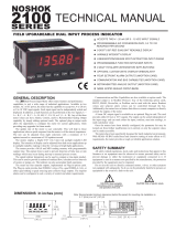
6
Fig. 1. View of the N30H meter
lsignaling of alarm operation – switching the alarm on causes
the highlight of the output number,
lgalvanic separation between connectors: alarm, supply, input,
analog output connections and RS-485 interface.
Protection degree from frontal side: IP65
Meter overall dimensions: 96 x 48 x 93 mm (with terminals).
The meter casing is made of plastics.
2. METER SET
The set is composed of:
- N30H meter .......................................................... 1 pc
- User’s manual ......................................................1 pc
- Guarantee card .................................................... 1 pc
- Clamps to fix in the panel ....................................4 pcs
- Seal ......................................................................1 pc
When unpacking the meter, please check whether the type and execu-
tion code on the data plate correspond to the order.

7
3. BASIC REQUIREMENTS, OPERATIONAL
SAFETY
In the safety service scope, the N30H meter meets the requirements of
the EN 61010-1 standard.
Observations concerning the operational safety
lAll operations concerning transport, installation, and commissioning
as well as maintenance, must be carried out by qualified, skilled per-
sonnel, and national regulations for the prevention of accidents must
be observed.
lThe programming of N30H meter parameters must be carried out
after disconnecting measuring circuits
lBefore switching the meter on, one must check the correctness of
connections.
lDo not connect the meter to the network through an autotransformer.
lBefore removing the meter housing, one must switch the supply off
and disconnect measuring circuits.
lThe meter is designed to be installed and exploited in electromag-
netic industrial environment conditions.
lNon-authorized removal of the housing, inappropriate use, incorrect
installation or operation, creates the risk of injury to personnel or meter
damage.
For more detailed information, please study the User’s Manual.
lWhen connecting the supply, one must remember that a switch or
a circuit-breaker should be installed in the building. This switch should
be located near the device, easy accessible by the operator, and
suitably marked as an element switching the meter off.

8
Fig. 3. Overall dimensions
Fig. 2. Meter fixing
4. INSTALLATION
The meter has separable strips with screw terminals, which enable the
connection of external wires of 2.5 mm2 cross-section. Strips of input
signals are protected against any accidental disconnection by means
of a screw joint.
One must prepare a hole of 92+0,6 ´ 45+0,6 mm in the panel, which the
thickness should not exceed 6 mm.
The meter is adapted to be mounted in a panel. The meter must be
introduced from the panel front with disconnected supply voltage. Be-
fore the insertion into the panel, one must check the correct placement
of the seal. After the insertion into the hole, fix the meter by means of
clamps (fig.2).

9
4.1. Signals Leads
Signals led out on the meter connectors are presented on the fig. 4.
All input signals are separated between them from remaining circuits.
Analog outputs are not separated between them. One don’t have to
take simultaneously advantage of voltage and current measure-
ments, since measuring circuits of voltage and current are not galva-
nically isolated.
Fig. 4. Description of signals on connection strips
· 1 A, 5 A – terminals for the current measurement on the 1 A
or 5 A range.
· 100 V, 500 V – terminals for the voltage measurement on the 100 V
or 500 V range.
· OC –output of open collector type with an npn output transistor.
The output is turned on in case of a measuring range overflow.

10
4.2. Examples of Connections
An example of the N30H meter connection for current measurement is
presented on the fig. 5.
However, an example of the meter connection in the configuration for
voltage measurement is presented on the fig. 6.
Fig. 5. Meter connection in the configuration for current measurement
Fig. 6. Meter connection in the configuration for voltage measurement

11
5. SERVICE
5.1. Display Description
Fig. 7. Description of the meter frontal plate
5.2. Messages after Switching the Supply on
After switching the supply on, the meter displays the meter name
N30H, and next the program version in the form „r x.xx” – where
x.xx is the number of the current program version or the number of a
custom-made execution. Next, the meter carries out measurements
and displays the value of the input signal. The meter sets automa-
tically the decimal point position, when displaying the value. The
format (number of places after the decimal point) can be limited by
the user.

12
5.3. Functions of Push-buttons
- Acceptation push-button:
Þ entry in programming mode (press and hold ca 3 seconds)
Þ moving through the menu – level selection,
Þ entry in the mode changing the parameter value,
Þ acceptation of the changed parameter value.
Þ stop the measurement – when holding down the push, the result
is not updated. The measurement is still carried out.
Þ Turning on the power supply of the meter while holding the button
– entering the software-update mode through RS485 interface
- Push-button increasing the value:
Þ display of maximal value, The pressure of the push-button causes
the display of the maximal value during ca 3 seconds.
Þ entry in the level of the parameter group,
Þ moving on the chosen level,
Þ change of the chosen parameter value – increasing the value.
- Push-button to change the digit:
Þ display of minimal value, The pressure of the push-button causes
the display of the maximal value during ca 3 seconds.
Þ entry in the level of parameter group,
Þ moving through the chosen level,
Þ change of chosen parameter value – shift on the next digit,
- Resignation push-button:
Þ entry in the menu monitoring the meter parameters (press and
hold ca 3 seconds),
Þ exit from the menu monitoring meter parameters,
Þ resignation of the parameter change,
Þ strict exit from the programming mode (press and hold
ca 3 seconds).
power on the transmitter to hold the button - enter firmware
update mode via RS-485 link parameters: speed 9600 kb /
s, 8N2 mode.

13
The pressure of the push-button combination and hol-
ding down them during ca 3 seconds causes the deletion of alarm signa-
ling. This operation acts only when the support function is switched on.
The pressure of the push-button combination causes
the erasing of the minimal value.
The pressure of the push-button combination causes
the erasing of the maximal value.
The pressure and holding down the push-button during ca 3
seconds causes the entry to the programming matrix. The program-
ming matrix can be protected by a safety code.
The pressure and holding down the push-button during ca 3
seconds causes the entry to the menu monitoring meter parameters.
One must move through the monitoring menu by means of and
push-buttons. In this menu, all programmable meter parame-
ters are available only for readout. In this mode, the menu Ser is not
available. The exit from the monitoring menu is carried out by means of
the push-button. In the monitoring menu, parameter symbols
are displayed alternately with their values.
The service algorithm of the meter is presented on the fig. 8.
The appearance of the symbols mentioned below on the display
means:
- Incorrectly introduced safety code.
- Overflow of the upper measuring range.
- Overflow of the lower measuring range.

14
Fig. 8. Service algorithm of the N30H meter

15
5.4. Programming
The pressure of the push-button and holding it down through
ca 3 seconds causes the entry to the programming matrix. If the entry is
protected by a password, then the safety code symbol SEC is display-
ed alternately with the set value 0. The write of the correct code causes
the entry to the matrix, the write of an incorrect code causes the display
of the ErCod inscription. The matrix of transitions to the programming
mode is presented on the fig. 9. The choice of the level is made by
means of the push-button, however the entry and moving
through the parameters of the chosen level is carried out by means of
the and push-buttons. Parameter symbols are display-
ed alternately with their current values. In order to change the value
of the chosen parameter, one must use the push-button. For
resignation from change, one must use the push-button. In or-
der to exit from the chosen level, one must chose the ----- symbol and
press the push-button. To exit from the programming matrix,
one must press during ca 1 second the push-button. Then, the
inscription End appears for ca 3 seconds and the meter transits to the
display of the measured value. In case of leaving the meter in the para-
meter programming mode, the automatic abandon of the programming
mode (the parameter and next the menu) follows after 30 seconds and
the meter transits to display the measured value.
5.4.1. Value Change Way of the Chosen Parameter
In order to increase the value of the chosen parameter, one must press
the push-button. A single pressure of the push, causes the
increase of the value of 1. The increase of value when displaying the
digit 9, causes the set of 0 on this digit (or the minus mark in case of
the oldest display digit). The change of the cursor position after pres-
sing the push-button. In order to accept the set parameter,

16
Fig. 9. Programming matrix

17
InP 1
Parameter
symbol Description Range of changes
tYP1 Kind of the connected input signal
500U – input 500 V.
100U – input 100 V
5A – input 5 A.
1A – input 1 A.
HoUr – current time.
Cnt1
The measurement time is expressed in
seconds. The result on the display pres-
ents the mean value counted in the Cnt1
period. This parameter is not taken into
consideration during the measurement
in the HoUr modes.
1...3600
Table 1
one must hold down the push-button. Then, the write of the
parameter follows and the display of its symbol alternately with the new
value. The pressure of the push-button during the change of
the parameter value will cause the resignation of the write.
5.4.2. Changing Floating-point Values
The change is carried out in two stages ( the transition to the next stage
follows after pressing the push-button:
1) setting values from the range -19999M...99999, similarly as for
integral values;
2) setting decimal point positions (00000., 0000.0, 000.00, 00.000,
0.0000); the push-button shifts the decimal point to the left,
however the push shifts the decimal point to the right;
The pressure of the push-button during the change of the pa-
rameter value will cause the resignation of the write.
5.4.3. Characteristic of Programmed Parameters
Programmed parameters and the range of their quantity changes are
presented in the table below.

18
Table 2
dISP
Parameter
symbol Description Range of changes
d_P
Minimal position of the decimal point
when displaying the measured value
- display format. This parameter is not
taken into consideration during the
CoUntH and HoUr modes.
0.0000 – 0
00.000 – 1
000.00 – 2
0000.0 – 3
00000 – 4
CoLdo Display colour, when the displayed
value is less than CoLLo.
rEd – red
grEEn – green
orAnG -orange
CoLbE Display colour, when the displayed
value is higher than CoLLo and less
than CoLHi.
CoLuP Display colour when the displayed value
is higher than CoLHi
CoLLo Lower threshold of colour change -19999..99999
CoLHi Upper threshold of colour change -19999..99999
ovrLo
Lower threshold of the display nar-
rowing. Values below the declared
threshold are signaled on the display by
the symbol.
-----
.
-19999..99999
ovrHi
Upper threshold of display narrowing.
Values above the declared threshold are
signaled on the display by the symbol.
-----
.
-19999..99999
Table 3
Ind
Parameter
symbol Description Range of changes
IndCp
Number of points of the individual char-
acteristic. For a value less than 2, the
individual characteristic is switched off.
The number of segments is the number
of points decreased of one.
The individual characteristic is not taken
into consideration in the HoUr modes.
1...21
Xn The point value for which we will expect
Yn (n-point number) -19999...99999
Yn Expected value for Xn. -19999...99999

19
Table 4
ALr1, ALr2, ALr3, ALr4
Parameter
symbol Description Range of changes
P_A1
P_A2
P_A3
P_A4
Input quantity, steering the alarm.
InP1 – Main input (indicated
value).
HoUr – real time clock
tYP1
tYP2
tYP3
tYP4
Alarm type. Fig. 12 presents the
graphical imaging of alarm types.
n-on – normal (transition
from 0 to 1),
n-oFF – normal (transition
from 1 to 0),
on – switched on,
oFF – switched off,
H-on – manually switched
on; till the change time of
the alarm type, the alarm
output remains switched on
for good,
H-oFF – manually switched
off; till the change time of
the alarm type the output
alarm remains switched off
for good.
PrL1
PrL2
PrL3
PrL4
lower Alarm threshold. -19999...99999
PrH1
PrH2
PrH3
PrH4
upper Alarm threshold. -19999...99999
dLY1
dLY2
dLY3
dLY4
Delay of alarm switching. 0...900

20
LEd1
LEd2
LEd3
LEd4
Support of alarm signalling. In
the situation when the support
function is switched on , after
the alarm state retreat, the
signalling diode is not blanked
. It signals the alarm state till its
blanking moment by means of
the push-but-
ton combination. This function
concerns only and exclusively
the alarm signaling, thus relay
contacts will operate without
support according to the chosen
type of alarm.
oFF – function switched off
on – function switched on
out
Parameter
symbol Description Range of changes
P_An Input quantity, on which the
analog output has to react..
InP – main input (indicated
value).
HoUr – Real Time Clock
AnL
Lower threshold of the analog
output. One must give the value,
for which we want to obtain the
minimal value of signal on the
analog output.
-19999...99999
AnH
Upper threshold of the analog
output. One must give the value
on which we want to obtain the
maximal value of signal on the
analog output( 10 V or 20 mA).
-19999...99999
tYPA Analog output type.
0_10U – napięciowe 0..10V
0_20A – prądowe 0..20mA
4_20A – prądowe 4..20mA
Table 5
/