
1001 New Hampshire Ave. Lakewood, NJ 08701
(732) 244-0010 ▪ (800) 337-3762 ▪ fax (732) 244-8140 ▪ www.permapure.com ▪ info@permapure.com
PERMA PURE LLC
Mini-GASS™
Sample Conditioning System User’s Manual
Rev 01

2
Contents
Unpacking ....................................................................................................3
Important safety warnings ..............................................................................5
General description ........................................................................................6
Specifications and Features ............................................................................7
Installation ...................................................................................................8
Electrical connections ................................................................................... 11
Start-up procedure ...................................................................................... 12
Preheating the system ................................................................................. 14
System fine tuning ...................................................................................... 14
Maintenance ............................................................................................... 15
Replacement parts ....................................................................................... 18
APPENDIX B: Dryer element replacement ....................................................... 20
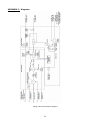
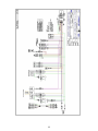
APPENDIX C: Diagrams ............................................................................... 22
APPENDIX E: Z-Purge Operation ................................................................... 28
APPENDIX F: Safety Interlock System ........................................................... 29

3
Unpacking
Perma Pure has made every effort to ship you a high quality product that has been thoroughly
inspected and tested. It has been carefully packed to ensure that it arrives at your facility in good
condition. Even though every effort has been made to prevent damage during transportation,
damage can occur by the carrier. This is out of Perma Pure’s control and is the responsibility of the
carrier to ensure that your equipment arrives intact and undamaged.
Inspect outside packaging. If there is any visible damage, inform the carrier at the time of
delivery. This inspection is important! Once the package is signed for,
responsibility for any visible damage then transfers to the consignee.
Unpack your equipment. Visually inspect the outside of your equipment for any damage.
If there is any damage, contact the carrier immediately. Generally, a carrier must be
notified within 24 hours of the delivery to make a hidden damage claim. Save the packing
material in the event a damage claim must be verified by the carrier.
Items in the carton include:
(1) Mini-GASS sampling system
(1) Heated line seal fitting
(1) User’s Manual
If any of the above parts are missing or damaged, call the helpline at:
(800) 337-3762
Or visit our website at:
www.permapure.com

4
Thank you for purchasing sample gas conditioning equipment from Perma Pure LLC. We
want your new sample gas conditioning equipment to operate safely. Anyone who installs or
uses this equipment should read this publication before installing or operating this
equipment.
To minimize the risk of potential safety problems, you should follow all applicable local and
national codes that regulate the installation and operation of your equipment. These codes vary
from area to area and usually change with time. It is your responsibility to determine which codes
should be followed and to verify the equipment, installation and operation is in compliance with
the latest revision of these codes.
At a minimum, you should follow all applicable sections of the National Fire Code, National
Electrical Code, and the codes of the National Electrical Manufacturer's Association (NEMA). There
may be local regulatory or government offices that can also help determine which codes and
standards are necessary for safe installation and operation.
Equipment damage or serious personal injury can result from the failure to follow all applicable
codes and standards. We do not guarantee the products described in this publication are suitable
for your particular application, nor do we assume any responsibility for your system design,
installation or operation. This product should not be operated in any manner that is inconsistent
with its intended use.
If you have any questions concerning the installation or operation of this equipment, or you need
additional information please call us at 1-800-337-3762.
This publication is based on information that was available at the time it was printed. At Perma
Pure we constantly strive to improve our products and services, so we reserve the right to make
changes to the products and/or publications at any time without notice and without any
obligation. This publication may also discuss features that may not be available in certain
revisions of the product.
This equipment is to be installed and operated by trained personnel, with sufficient command of
the English language to clearly understand the instructions and safety warnings.
TRADEMARKS
Nation® and Teflon® are registered trademarks of EI DuPont de Nemours
Copyright 1996-2014, Perma Pure LLC. All Rights Reserved.
WARNING

5
Important safety warnings
Please be sure to review the following basic safety procedures. These procedures
represent the MINIMUM requirements to operate the equipment safely. It is the
ultimate responsibility of the operator to ensure proper safety practices are utilized at
the point of operation.
• This equipment is NOT designed to operate in a wet environment.
• Condensate is potentially dangerous. NEVER handle drain lines or any other item that
may have come in contact with the gas stream or any hazardous material, without adequate
personal protective equipment. ALWAYS assume that any liquid present is hazardous.
• Sample gas is potentially dangerous. A leak test is recommended at initial startup and as
often as necessary to maintain a safe working environment around the equipment. The gas
stream exhaust must exit away from all personnel to prevent dangerous exposure.
• NEVER operate the equipment with any part of the enclosure unsecured. All operated
doors and covers must be in place and secured prior to operation. Electrical current may be
present behind covers or doors, even if tools are not necessary to access these components.
• NEVER attempt service on this equipment without first disconnecting all energy sources.
Repair of this equipment should only be done by properly trained personnel that are familiar
with the potential risks involved with servicing of the equipment.
• NEVER replace fuses with types other then the sample specification of type and current. Do
not bypass this or any other safety device.
• NEVER operate this equipment if it is visibly damaged or the possibility exists that it may have
been damaged.
• The use of components that have not been purchased through an authorized Perma Pure
dealer or directly from Perma Pure may compromise the safety of the operator. Additionally,
use of non-authorized components may change the operating characteristics of this equipment.
Any changes to the equipment that modify its operation in any way are dangerous, and are
strictly prohibited.
• Read the entire operating manual before attempting to set up or operate the equipment.
• Please heed all warning labels that are on the equipment. They are there to remind you of
possible hazardous conditions.
• Verify the integrity of any mechanical and/or electrical connections that are made to the unit.
• Verify that the unit is connected to the proper rated power for the system.
• Verify that the unit is plumbed properly to operate effectively.

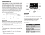
6
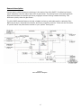
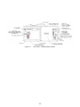
General description
Proven tube-in-shell membrane technology is the basis of the Mini-GASS™ Conditioning System,
which selectively removes water vapor from a gas stream. The driving force is the vapor pressure
differential between the sample gas and a purge gas counter-flowing outside the tubing. This
difference quickly dries the gas stream.
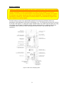
The Mini-GASS standard features include a heated enclosure, particulate and/or coalescing filter,
Nafion® gas dryer, temperature controller and dryer purge flow controls. There are also a number
of options which may have been included in your system. See Figure 1
Figure 1
Mini-GASS flow diagram

7
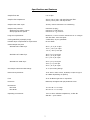
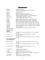
Specifications and Features
Sample flow rate
0 to 10 lpm
Sample inlet temperature
250°F (121°C) max. with stainless steel filter
230°F (110°C) max. with Kynar filter
Sample inlet water vapor
30% by volume maximum non condensing
Sample inlet pressure:
Without purge eductor option
With purge eductor option
maximum 20 psig;
minimum 5” H2O vacuum
minimum 10” H20 vacuum
Purge air requirements
Maximum 1 cfm of oil-free instrument air or nitrogen
with less than -40°C dew point
Cooling Manifold (w/sample pump)
2 CFM clean, dry air @ 80PSIG
Heatless Dryer compressed air requirement
60-100 PSIG
Outlet sample dew point
With PD-200T-24SS dryer
26° F (-4° C) at 10 lpm
12° F (-12° C) at 5 lpm
-12° F (-25° C) at 2 lpm
With PD-100T-24SS dryer
36° F (2° C) at 10 lpm
26° F (-4° C) at 5 lpm
6° F (-15° C) at 2 lpm
With PD-50T-24SS dryer
42° F (5° C) at 10 lpm
34° F (1° C) at 5 lpm
22° F (-6° C) at 2 lpm
Gas sample inlet and outlet fittings
¼” or 3/8” tubing fittings
Electrical requirements
115V ±10% or 230V ±10%, 50/60Hz, 5.0A/2.5A (up to
914 Watts depending on options)
Fuse
3A or 5A BUSS type AGC or equivalent
Enclosure
NEMA 4X, Fiberglass with polycarbonate cover
Dimensions:
MG-1228
12” W x 28” H x 7” Deep
MG-2812P
28” W x 12” H x 7” Deep
Operating environment
-20°C to 40°C ambient temperature; 0-95% RH
Altitude – up to 2000m

8
Installation
Mounting
1. Install Mini-GASS 1228W or 1228p system on vertical surface with dryer/filter compartment
on top and control compartment on bottom. Model 2812T operates horizontally (Left to
Right).
2. Place mounting feet (if used) on each corner of enclosure with slotted end protruding at a
45° angle.
3. Drop mounting screw in from top and tighten into foot.
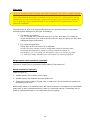
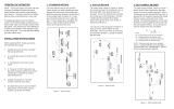
Connections (Refer to figure 2)
Heated sample line
1. Install heated line sealing fitting by threading hub into sleeve.
2. Ensure o-ring seal is installed on outside of enclosure (between
sleeve & enclosure wall).
3. Run heated sample line through entry seal and into enclosure.
4. Connect sample line to compression fitting (labeled “Wet
Sample In”)
5. Shrink entry seal tubing around heated sample line with heat gun.
6. Connect sample outlet port of Mini-GASS to sample line running to analyzers. High
temperature heated line is not necessary for this connection. If sample line will be exposed
to freezing temperatures, freeze protected line is recommended.
Purge air supply Instrument air
Purge gas must be of instrument grade with dew point no higher than -40°C.
1. All models come with a control panel that includes a flow meter and regulator.
2. For all models, connect a 30-100 psig purge gas supply line to the ¼” female NPT
purge inlet port of membrane dryer labeled “Instrument Air”.
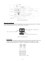
Heatless air dryer (optional)
1. Connect oil-free compressed air line to port labeled “Purge Gas Inlet”
2. A ¼” FNPT bulkhead fitting on bottom of enclosure is the heatless dryer purge air
exhaust, see figure 3. Humid air can be vented to atmosphere or piped to a
remote location. Use suitable size piping.
HEATED SAMPLE
LINE
FITTING
SLEEVE
O-RING
SEAL
FITTING
HUB
ENCLOSURE
Figure 2

9
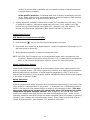
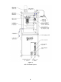
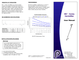
Purge air exhaust
Failure to properly vent the system may result in personal injury and/or property damage!
The gas exhausted from the purge exhaust port under normal operation is humid air.
However, in the event of an internal failure of the sample gas dryer installed in the system,
the exhaust may contain sample gas that may be hazardous. The purge exhaust must be
permanently routed to a vent system or directly outdoors. Do not allow the purge to vent
into a structure or confined space.
Connect tubing or pipe of an appropriate material from the purge exhaust outlet to a
permanent vent designed for this type of discharge. 1/4” I.D. tubing can be used for runs up
to 10 feet. Use larger I.D. tubing for longer exhaust lines. Too small of an ID and/or too long
of a piping run will cause inadequate purge vacuum performance or collapse of the dryer
membrane tubes resulting in poor drying performance and/or high sample gas flow
restriction.
Figure 3 - Mini-GASS Sampling System

10
Filter drain
Failure to connect the drain properly may result in personal injury and/or property damage!
The condensate and sample gas exhausted during draining of the coalescing filter can be
hazardous and must be permanently routed to a drainage system designed to accept the
type of discharge that is expected based on the composition of the gas sampled at the
particular installation.
Connect tubing or pipe of an appropriate material from the drain outlet to a permanent
drainage system designed for this type of discharge.
1. For vacuum style drains:
1/4” I.D. tubing can be used for runs up to 10 feet. Use larger I.D. tubing for
longer exhaust lines. Too small of an ID and/or too long of a piping run will cause
inadequate drain performance.
2. For pressure style drains:
Tubing with an ID of at least 1/8” is adequate.
Connect line from eductor outlet to designated collection/exhaust basin
containing acid absorption media to prevent release of exhaust to
surrounding. 1/4” I.D. tubing can be used for runs up to 10 feet, or larger
I.D. tubing for longer exhaust lines. Line should not restrict purge flow.
Purge eductor inlet connection (optional)
Connect air supply line to compression fitting labeled “Instrument Air”.
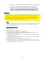
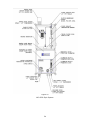
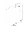
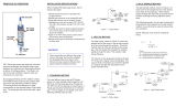
Steam connection (optional)
(Refer to figure 4)
1. Insulate supply line to steam control valve.
2. Insulate supply line between valve and steam coil.
3. Supply low pressure steam (50 psig max) to steam coil. Do not exceed this pressure or
overheating may occur.
Outlet end of steam coil located at lower left side of enclosure is connected to a thermostatic
steam trap to allow condensed steam to drain in a controlled manner. Condensate can be
piped to a wastewater drain or to condensate recovery system.

11
Figure 4 - Steam heated Mini-GASS
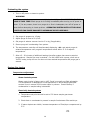
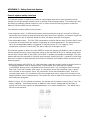
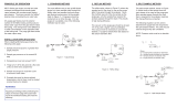
Electrical connections
Mini-GASS Model #1228 and 2812T (Transportable) have a power cord and plug for 115 VAC and
power cord with pigtail wires for the 230 VAC version. See Figure 5.
Figure 5 – Electrical Connections
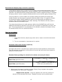
Alarm Relays
The alarm relay connection are made via 6 pole terminal block that will allow for field wiring
of alarm relays for connection of external alarm equipment (refer to Figure 6). Relay
contacts are rated at 250 VAC, 3A, resistive. See Appendix F for additional information.
Figure
6 – Alarm Relays
Blue
–
Connect neutral or Line L2 here
Green
/yellow
–
Connect ground earth
here
Brown
–
Connect Line L1 here

12
Note-External Sample pump connection/operation
If an external sample pump is used with the sample pump plumbed downstream (after) the
MiniGASS, the optional purge eductor may be necessary, and is recommended for proper
operation. This assumes that the sample gas stream is under a negative pressure. If needed
the purge eductor vacuum regulator setting should be set so that the gauge indicates 5”Hg.
The purge eductor is used to balance the pressure difference between the sample gas
stream pressure and the purge air pressure inside the Nafion Dryer. If a vacuum is drawn
on the sample stream without additional vacuum on the purge gas, the difference in
pressure may collapse the Nafion Dryer tubes. Warning: This situation will likely result in
premature failure of the Nafion Dryer.
If an external sample pump is used upstream (before) the MiniGASS there will likely be
additional maintenance required for the pump due to presence of potentially corrosive, wet
gas. The purge gas eductor is not necessary in this situation, because the sample exiting
the sample pump will be at a positive pressure.
Start-up procedure
Setup Check
1. Check that electrical, sample purge drain and /or steam connections have been
made.
2. Turn on compressed or instrument air to system.
Automatic Filter Drain Control (Optional)
Automatic filter drain is controlled by a repeat cycle timer that operates a solenoid valve.
Two DIP switches are located on timing device to control drain and cycle times located on
backside of control panel.
Standard factory setting is to drain for 0.1 minute once every 24 hours.
Drain Time (left DIP switch)
0.1 minutes (1st switch on – all others off)
To
102.3 minutes (all switches on)
Cycle Time (right DIP switch)
1 hour (1st switch on – all others off) To
1023 hours (all switches on)
1. Adjust purge air pressure regulator to about 15 psig. Purge regulator also supplies
compressed air for filter drain, if equipped.
Sample under vacuum: Purge air regulator will control air pressure to
eductor of the automatic filter drain. Regulator must be set to provide ample

13
vacuum to remove filter condensate but not excessive enough to cause interruption
in sample flow to analyzers.
Under positive pressure: Condensate drain flow is directly controlled by solenoid
valve. When solenoid valve is actuated (opened), positive pressure in filter housing
purges condensate out of system through drain line.
2. Initially adjust DIP switches on drain timer to drain for 6 seconds every 24 hours. Time
on switches is additive. Left switch should have only top 0.1 min. switch in the “ON”
position and right switch should have 8 and 16 hr. switches in the “ON” position. Time
periods may need further adjustments after system has been in operation.
Temperature Control
PID Electronic Temperature Controller
1. Press and hold “ ” key on the CAL Controls temperature controller.
2. Press either up or down key to adjust setpoint. Setpoint temperature will change one °C
with each press of arrow key.
3. When desired temperature is reached, release both keys.
NOTE: MG-1228, 2812T systems have a low temperature alarm that is programmed into
controller. Default temperature setting for alarm is 5° C below setpoint temperature.
Refer to CAL Controls temperature controller manual for more information.
Steam Temperature Control
Steam heated systems are regulated by a thermostatic steam control valve located in the
purge air exhaust stream. This valve is preset at the factory to an appropriate temperature
determined by sample conditions. A typical setpoint temperature is 180° F which is the
approximate temperature of the purge air exhaust indicated by analog thermometer located
in the purge air exhaust stream.
Safety Interlocks
Systems equipped with safety interlocks which controls the sample pump in the event of low
purge airflow or low temperature in the system. To accomplish this, a differential pressure
switch in the purge air inlet senses the flow of purge air and energizes a relay. This relay
then sends power to the contacts of a second relay which will energize only when
temperature set point has been reached. After energizing, this second relay sends
power to the sample valve and the valve will open and allow sample flow. Under normal
operating conditions both safety relays will remain energized (When the system is operating
normally, open contacts will close and remain closed). Alarm relays may be field wired to
initiate an external alarm. See Appendix F for additional information.

14
Preheating the system
1. Turn on AC power or steam to system.
WARNING!
On AC powered units, temperature control display should light. DO NOT BEGIN SAMPLE
FLOW AT THIS TIME! Check purge air is flowing immediately after turning on AC power or
steam. If, for any reason, there is no purge air or flow is inadequate, turn off AC power or
steam before attempting to locate problem. OPERATING SYSTEM WITH LITTLE OR NO
PURGE AIR CAN CAUSE DAMAGE TO MEMBRANE DRYER ASSEMBLY.
2. Set purge air pressure to 15 psig.
3. Adjust purge air flow to 20 L/min.
4. Set purge air eductor vacuum level to 5 in-Hg (if applicable).
5. Ensure purge air is exhausting from system.
6. The temperature controller will be alternately displaying –AL– and actual purge air
exhaust temperature until purge air temperature comes within 5° C of setpoint
temperature.
7. Allow 15 – 30 minutes of additional heating time after system has come to setpoint
temperature. Sample flow may be started. For Mini-GASS with a pump, when set on
“AUTO” mode, pump will turn on when unit has reached temperature and purge gas is
sensed.
System fine tuning
Temperature adjustment
Steam heated systems
Steam control valve is factory set to 180° F and is normally not field adjustable.
This temperature is adequate for most applications in which sample gas water
content is not in excess of 50% water vapor by volume. Consult factory if
condensation in sample tubing is detected.
Electrically heated systems
1. Temperature set point should be set to 5°C above sample gas stream
temperature.
2. Check that no condensate is present in sample line between filter and dryer.
3. If water droplets are visible, increase temperature of filter/dryer compartment by
5° C.
212
15 of

15
4. Allow about ½ hour for system to stabilize and then check again for condensate.
5. If necessary, continue to increase temperature in 5° C increments until
condensate is no longer visible. Do not exceed 100° C! Maximum system
temperature is 100° C. Operation above this temperature can cause damage to
Nafion dryer. It is essential that purge gas flows continuously and
setpoint temperature is not above 100° C to prevent damage to dryer.
Maintenance
If the sample gas is hazardous, care should be taken when opening the enclosure.
Small leaks can allow the sample gas to build in the enclosure and take appropriate
precautions, including PPE suitable for handling the sample gas and appropriate
ventilation to prevent unsafe concentrations of gas.
Filters
If system is fitted with a pre-filter, it should be checked regularly to ensure that the element
is in good condition. If element appears to be dirty or begins to cause flow restriction in
system, it should be replaced.
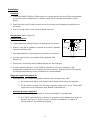
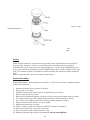
Filter Element Replacement
(Refer to Figure 7)
1. Loosen bolt on bottom of filter.
2. Gently pull apart assembly and remove old element.
3. Place new element into grooves in top and bottom of housing.
4. When re-assembling, inspect for o-rings on top and bottom caps and on center bolt.
5. Install glass shell onto bottom piece.
6. Place new element in groove in bottom piece. Be sure that element is seated correctly
and parallel to glass shell.
7. Carefully mate bottom assembly onto top piece. Slight twisting motion may be required
to allow shell to slip over o-ring seal.
8. Visually make sure element is seated correctly in top groove.
9. Replace bolt through hole in bottom piece and screw clockwise into top piece. Do not
over-tighten center bolt. It should be just tight enough so it does not vibrate loose. Over-
tightening will not help the filter to seal.

16
Figure 7 – Filter
Element Replacement
212
16 of
Dryers
Under normal conditions, Perma Pure dryers require little maintenance and can last for
several years. However, if there is no pre-filter and the tubing becomes clogged or
saturated with water, the dryer may require cleaning or repair. When disassembling the
dryer, note that the end fittings on the PD-SERIES dryer can be easily rotated on the shell
tube. This rotation should be avoided to prevent twisting the membrane tubes inside the
shell.
Refer to Appendix B for PD dryer element replacement.
Ammonia Scrubber
Media Replacement: When deposits are visible on 75% of the scrubber, scrubbing media
needs to be replaced.
1. Unscrew thumbscrew on bottom of housing.
2. Swing yoke to one side.
3. Separate housing and bottom cap as an assembly from top cap.
4. Remove spring and top screen.
5. Remove old media and dispose of properly (rinse housing with soapy water to clean).
6. Fill housing with 50cc of Berl Saddles (tap housing to allow material to settle).
7. Pour 150cc of Scrubbing Media (tap housing to allow material to settle).
8. Replace stainless steel screen on top of media.
9. Replace spring on top of screen.
10. Clean o-rings on shell and inside top manifold (replace if necessary).
11. Place center tube into o-ring seal in top cap.
12. Push and twist to seal housing around o-ring.
13. Replace yoke and finger tighten thumbscrew (do not over tighten).

17
Fuse
Fuse Replacement
1. A blown fuse is an indication of a possible malfunction.
2. Turn cap marked “FUSE” counter-clockwise ¼ turn and the fuse holder will come out.
3. Remove the blown fuse and replace with one of equal amperage rating. The standard
fuse is a BUSS type AGC or equivalent.
4. After installing correct replacement fuse, re-install fuse holder by pressing inward and
twisting ¼ turn clockwise.
Hint: If system has blown two fuses, service is most likely needed by qualified personnel.

18
Replacement parts
MG-PR
Purge Air Regulator
MG-DTC
Digital temperature controller, single channel
MG-TCS
J-Type thermocouple
MG-SSR
Solid state relay
MG-FM
Flow meter, purge gas (0-60 lpm)
MG-PR
Pressure regulator, purge gas or eductor
MG-DPS
Differential pressure switch for purge flow detection
MG-PG-0-30
Pressure gage, purge gas (0-30 psi)
MG-VG-0-60
Vacuum gage, purge eductor (0-30”Hg)
SV-K10
Safety interlock solenoid valve, Kynar, 110V/60Hz
SV-K20
Safety interlock solenoid valve, Kynar, 220V/50Hz
FF-DCV
Drain check valve, polypropylene, for vacuum drain
DVV-B10
Drain solenoid valve, brass, for vacuum drain 110V/60Hz
DVV-B20
Drain solenoid valve, brass, for vacuum drain 220V/50Hz
DVP-K10
Drain solenoid valve, kynar, for pressure drain 110V/60Hz
DVP-K20
Drain solenoid valve, kynar, for pressure drain 220V/50Hz
MG-DVT
Drain valve timer
MG-DC
Mounting clamps for dryer (specify dryer model)
For Dryers with
two part end
fittings
PD-50T-24E
50 tube dryer replacement element, 24” long, includes
O-rings
PD-100T-24E
100 tube dryer replacement element, 24” long,
Includes O-rings
PD-200T-24E
200 tube dryer replacement element, 24” long, includes
O-rings
For Dryers with one
part end fittings
PD-50T-24E-M
50 tube dryer replacement element, 24” long, includes
O-rings
PD-100T-24E-M
100 tube dryer replacement element, 24” long, includes
O-rings
PD-200T-24E-M
200 tube dryer replacement element, 24” long,
includes O-rings
FF-250-E-2.5G
Replacement filter element
FF-350G
Replacement glass shell for filter
FF-250-3
Replacement O-ring set, set of 3 rings
AS-200-08-EB
Media replacement for ammonia scrubber, bulk supply, 5
fillings
MG-PUMPKIT
Pump repair kit, Teflon diaphragm
3FEC-002
Ceramic filter element for MG-1228P

19
APPENDIX A: Warranty and disclaimers
Perma Pure LLC
Perma Pure (Seller) warrants that product supplied hereunder shall, at the time of delivery to
Buyer, conform to the published specifications of Seller and be free from defects in material and
workmanship under normal use and service. Seller’s sole obligation and liability under this
warranty is limited to the repair or replacement at its factory, at Seller’s option, of any such
product which proves defective within one year after the date of original shipment from seller’s
factory (or for a normal usable lifetime if the product is a disposable or expendable item) and is
found to be defective in material or workmanship by Seller’s inspection.
Buyer agrees that (1) any technical advice, information, suggestions, or recommendations given to
Buyer by Seller or any representative of Seller with respect to the product or the suitability or
desirability of the product for an particular use or application are based solely on the general
knowledge of Seller, are intended for information guidance only, and do not constitute any
representation or warranty by Seller that the product shall in fact be suitable or desirable for any
particular use or application; (2) Buyer takes sole responsibility for the use and applications to
which the product is put and Buyer shall conduct all testing and analysis necessary to validate the
use and application to which Buyer puts the product for which Buyer may recommend the use or
application of the product by others; and (3) the characteristics, specifications, and/or properties
of the product may be affected by the processing, treatment, handling, and/or manufacturing of
the product by Buyer or others and Seller takes no responsibility for he nature or consequence of
such operations or as to the suitability of the product for the purposes intended to be used by
Buyer or others after being subjected to such operations.
SELLER MAKES NO OTHER WARRANTY, EXPRESS OR IMPLIED, OF THE PRODUCT SUPPLIED HEREUNDER,
INCLUDING, WITHOUT LIMITATION, IMPLIED WARRANTIES OF MERCHANTABILITY AND FITNESS FOR
PARTICULAR PURPOSE, AND ALL SUCH WARRANTIES ARE HEREBY EXPRESSLY EXCLUDED. SELLER
SHALL HAVE NO LIABILITY FOR LOSS OF PROFITS, OR SPECIAL, INCIDENTAL, OR CONSEQUENTIAL
DAMAGES UNDER ANY CIRCUMSTANCES OR LEGAL THEORY, WHETHER BASED ON NEGLIGENCE,
BREACH OF WARRANTY, STRICT LIABILITY, TORT, CONTRACT, OR OTHERWISE. SELLER SHALL IN NO
EVENT BE LIABLE IN RESPECT OF THIS ORDER AND OR PRODUCT DELIVERED ON ACCOUNT OF THIS
ORDER FOR ANY AMOUNT GREATER THAN THAT PAID TO SELLER ON ACCOUNT OF THIS ORDER.

20
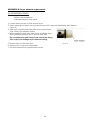
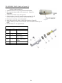
APPENDIX B: Dryer element replacement
TO DISASSEMBLE DRYER
Tools Needed:
- Phillips head screwdriver
- unsharpened pencil with eraser
1. Loosen locking screws on both ends of dryer.
2. Insert eraser end of pencil into one sample port until it rests on tube header face (Refer to
Figure 8).
3. Hold dryer vertically and place other end of pencil down
onto a hard, slip resistant surface.
4. While supporting shell tube, push lower end fitting down
with consistent pressure until it slips off shell tube.
Do not attempt to pull fitting from shell tube; doing
this is likely to damage dryer element tubing.
5. Repeat steps 2-4 for other end.
6. Remove one o-ring from tube header.
7. Pull tube element from opposite end of dryer.
Figure 8
Page is loading ...
Page is loading ...
Page is loading ...
Page is loading ...
Page is loading ...
Page is loading ...
Page is loading ...
Page is loading ...
Page is loading ...
Page is loading ...
-
 1
1
-
 2
2
-
 3
3
-
 4
4
-
 5
5
-
 6
6
-
 7
7
-
 8
8
-
 9
9
-
 10
10
-
 11
11
-
 12
12
-
 13
13
-
 14
14
-
 15
15
-
 16
16
-
 17
17
-
 18
18
-
 19
19
-
 20
20
-
 21
21
-
 22
22
-
 23
23
-
 24
24
-
 25
25
-
 26
26
-
 27
27
-
 28
28
-
 29
29
-
 30
30


Ask a question and I''ll find the answer in the document
Finding information in a document is now easier with AI
Related papers
-
 Perma Pure Indi-GASS User manual
-
 Perma Pure Readi-GASS RG-1024 User manual
-
 Perma Pure ACES User manual
-
 Perma Pure MD-R Series User manual
-
 Perma Pure AS-Series User manual
-
 Perma Pure MD-700 Series User manual
-
 Perma Pure MH-Series User manual
-
 Perma Pure MD-Series User manual
-
 Perma Pure PD-Series User manual
-
 Perma Pure Baldwin™-Series 5210D User manual


Other documents
-
 PerAlert FW 25-75 Operating instructions
-
Campbell Scientific TGA Owner's manual
-
Rosemount OCX 8800 O2 / Combustibles Transmitter General Purpose-Rev 2.0 Owner's manual
-
-
Emerson Process Management OCX 8800 User manual
-
-
 Thermo Fisher Scientific PRO2001WHP User manual
-
-
-
 Thermo Fisher Scientific PRO903 User manual


