Page is loading ...

Perma Pure LLC • A Halma Company • [email protected]om • www.permapure.com
Telephone: 732-244-0010 • Toll Free: 800-337-3762 • Fax: 732-244-8140
1001 New Hampshire Ave., Lakewood, NJ 08701 USA
Readi-GASS™
Model RG-1024
Sample Conditioning
System Featuring
Nafion™ Membrane
Drying Technology
User’s Manual

Model RG-1024 User’s Manual
Doc. #562: Revision: 004
Page 2 of 29
©2018 Perma Pure LLC. All rights reserved. Specifications subject to change.
CONTENTS
3. Caution Statement
4. Important Safety Warnings
5. Warranty Information
6. Unpacking
7. Specifications and Features
8. Readi-GASS System
8. Readi-GASS Assembly
8. System Enclosure
8. Utility Connections
9. Installation
9. Plumbing and Electrical Connections
9. Mounting
9. Heated Sample Inlet and Dry Sample
Outlet
10. Atmospheric Air Inlet
10. Filter Drain Outlet
11. Exhaust Vent
11. Power Connection
12. Alarm Signal Connection
13. System Component Locations
14. Sample Gas Flow
14. Pressure Snubber (Restriction Orifice)
14. Sample Gas Filters/Eductor
14. Sample Gas Dryer
15. Sample Isolation Valve
15. Filter Drain System
16. Purge Air Flow
16. Filters
16. Purge Gas Dryer
16. Flowmeters and Needle Valves
16. Vacuum Gauges
16. Eductors
17. Compressed Air Flow
17. Isolation Valve Operator
17. Pressure Regulators
17. Drain Eductor Needle Valve
18. Electronic Control and Instrumentation
18. Temperature Controller
18. Temperature Alarm Relay
18. Pressure Switch
18. Alarm Relay
18. Thermal Insulation
18. System Power
19. Systems Operation Monitoring
19. Alarm Output Operation
19. System Power Indicator
20. Start-Up Procedure
20. Primary Sample Handing System Check
Procedure
20. Readi-GASS System Check Procedure
21. Shutdown Procedure
22. Dos & Don’ts
23. Maintenance
23. Filters
23. Nafion™ Membrane Dryer
24. Replacement Parts
24. Filters
24. Nafion™ Membrane Dryer
24. Fuse Replacement
25. Appendix A: Drawings
29. Appendix B: Readi-GASS
Commissioning/Troubleshooting Kit

Model RG-1024 User’s Manual
Doc. #562: Revision: 004
Page 3 of 29
©2018 Perma Pure LLC. All rights reserved. Specifications subject to change.
Thank you for purchasing sample gas conditioning equipment from Perma Pure LLC. We want your new sample
gas conditioning equipment to operate safely. Anyone who installs or uses this equipment should read this
publication before installing or operating this equipment.
To minimize the risk of potential safety problems, you should follow all applicable local and national codes that
regulate the installation and operation of your equipment. These codes vary from area to area and usually
change with time. It is your responsibility to determine which codes should be followed and to verify the
equipment, installation and operation is in compliance with the latest revision of these codes.
At a minimum, you should follow all applicable sections of the National Fire Code, National Electrical Code, and
the codes of the National Electrical Manufacturer’s Association (NEMA). There may be local regulatory or
government offices that can also help determine which codes and standards are necessary for safe installation
and operation.
Equipment damage or serious personal injury can result from the failure to follow all applicable codes and
standards. We do not guarantee the products described in this publication are suitable for your particular
application, nor do we assume any responsibility for your system design, installation or operation. This product
should not be operated in any manner that is inconsistent with its intended use.
If you have any questions concerning the installation or operation of this equipment, or you need additional
information, please call us at 1-800-337-3762.
This publication is based on information that was available at the time it was printed. At Perma Pure we
constantly strive to improve our products and services, so we reserve the right to make changes to the products
and/or publications at any time without notice and without any obligation. This publication may also discuss
features that may not be available in certain revisions of the product.
Trademarks
Nafion™, Viton™ and Teflon™ are registered trademarks of The Chemours Company.
Kynar® is a registered trademark of Arkema Inc
Caution Statement

Model RG-1024 User’s Manual
Doc. #562: Revision: 004
Page 4 of 29
©2018 Perma Pure LLC. All rights reserved. Specifications subject to change.
IMPORTANT SAFETY WARNINGS
Please be sure to review the following basic safety procedures. These procedures represent the
MINIMUM requirements to operate the equipment safely. It is the ultimate responsibility of the operator
to ensure proper safety practices are utilized at the point of operation.
NEVER attempt to operate this equipment in an explosive, wet, or otherwise hazardous area.
NEVER exceed any specified rating for the equipment. Voltage, temperature and pressure ratings
must be closely observed and not exceeded. Voltage rating of the equipment MUST match the rating
on the data label. Please make sure that it matches before powering up the equipment.
Condensate is potentially dangerous. NEVER handle drain lines, impingers or any other item that
may have come in contact with the gas stream or any hazardous material, without adequate personal
protective equipment. ALWAYS assume that any liquid present is hazardous.
Sample gas is potentially dangerous. A leak test is recommended at initial start-up and as often as
necessary to maintain a safe working environment around the equipment. The gas stream exhaust
must exit away from all personnel to prevent dangerous exposure.
NEVER operate the equipment with any part of the enclosure unsecured. All operated doors and
covers must be in place and secured prior to operation. Electrical current may be present behind
covers or doors, even if tools are not necessary to access these components.
NEVER attempt service on this equipment without first disconnecting all energy sources. Repair of
this equipment should only be done by properly trained personnel that are familiar with the potential
risks involved with servicing of the equipment.
NEVER replace fuses with types other than the sample specification of type and current. Do not
bypass this or any other safety device.
NEVER operate this equipment if it is visibly damaged or the possibility exists that it may have been
damaged.
The use of components that have not been purchased through an authorized Perma Pure dealer or
directly from Perma Pure may compromise the safety of the operator. Additionally, use of non-
authorized components may change the operating characteristics of this equipment. Any changes to
the equipment, that modify its operation in any way, are dangerous, and are strictly prohibited.
Read the entire operating manual before attempting to set up or operate the equipment.
Please heed all warning labels on the equipment. They are there to remind you of possible hazardous
conditions.
Verify the integrity of any mechanical and/or electrical connections that are made to the unit.
o Verify that the unit is connected to the properly rated power for the system.
o Verify that the unit is plumbed properly to operate effectively.

Model RG-1024 User’s Manual
Doc. #562: Revision: 004
Page 5 of 29
©2018 Perma Pure LLC. All rights reserved. Specifications subject to change.
WARRANTY INFORMATION
Perma Pure (Seller) warrants that product supplied hereunder shall, at the time of delivery to Buyer, conform to
the published specifications of Seller and be free from defects in material and workmanship under normal use
and service. Seller’s sole obligation and liability under this warranty is limited to the repair or replacement at its
factory, at Seller’s option, of any such product which proves defective within one year after the date of start-up
(or within 18 months after original shipment at the discretion of Seller) and is found to be defective in material or
workmanship by Seller’s inspection.
Buyer agrees that (1) any technical advice, information, suggestions, or recommendations given to Buyer by
Seller or any representative of Seller with respect to the product or the suitability or desirability of the product for
an particular use or application are based solely on the general knowledge of Seller, are intended for information
guidance only, and do not constitute any representation or warranty by Seller that the product shall in fact be
suitable or desirable for any particular use or application; (2) Buyer takes sole responsibility for the use and
applications to which the product is put and Buyer shall conduct all testing and analysis necessary to validate the
use and application to which Buyer puts the product for which Buyer may recommend the use or application of
the product by others; and (3) the characteristics, specifications, and/or properties of the product may be
affected by the processing, treatment, handling, and/or manufacturing of the product by Buyer or others and
Seller takes no responsibility for he nature or consequence of such operations or as to the suitability of the
product for the purposes intended to be used by Buyer or others after being subjected to such operations.
SELLER MAKES NO OTHER WARRANTY, EXPLICIT OR IMPLIED, OF THE PRODUCT SUPPLIED
HEREUNDER, INCLUDING, WITHOUT LIMITATION, IMPLIED WARRANTIES OF MERCHANTABILITY AND
FITNESS FOR PARTICULAR PURPOSE, AND ALL SUCH WARRANTIES ARE HEREBY EXPRESSLY
EXCLUDED. SELLER SHALL HAVE NO LIABILITY FOR LOSS OF PROFITS, OR SPECIAL, INCIDENTAL, OR
CONSEQUENTIAL DAMAGES UNDER ANY CIRCUMSTANCES OR LEGAL THEORY, WHETHER BASED ON
NEGLIGENCE, BREACH OF WARRANTY, STRICT LIABILITY, TORT, CONTRACT, OR OTHERWISE.
SELLER SHALL IN NO EVENT BE LIABLE IN RESPECT OF THIS ORDER AND OR PRODUCT DELIVERED
ON ACCOUNT OF THIS ORDER FOR ANY AMOUNT GREATER THAN THAT PAID TO SELLER ON
ACCOUNT OF THIS ORDER.

Model RG-1024 User’s Manual
Doc. #562: Revision: 004
Page 6 of 29
©2018 Perma Pure LLC. All rights reserved. Specifications subject to change.
UNPACKING
Perma Pure has made every effort to ship you a high-quality product that has been thoroughly inspected and
tested. It has been carefully packed to ensure that it arrives at your facility in good condition. Even though every
effort has been made to prevent damage during transportation, damage can occur by the carrier. This is out of
Perma Pure’s control and is the responsibility of the carrier to ensure that your equipment arrives intact and
undamaged.
Inspect outside packaging. If there is any visible damage, inform the carrier at the time of delivery. This
inspection is important! Once the package is signed for, responsibility for any visible damage
then transfers to the consignee.
Unpack your equipment. Visually inspect the outside of your equipment for any damage. If there is any
damage, contact the carrier immediately. Generally, a carrier must be notified within 24 hours of the
delivery to make a hidden damage claim. Save the packing material in the event a damage claim must be
verified by the carrier.
Items in the carton include:
(1) Readi-GASS sampling system
(1) Inlet Air Filter
(1) User’s Manual
If any of the above parts are missing or damaged, call the helpline at (800) 337-3762 ext-149.

Model RG-1024 User’s Manual
Doc. #562: Revision: 004
Page 7 of 29
©2018 Perma Pure LLC. All rights reserved. Specifications subject to change.
SPECIFICATIONS AND FEATURES
Refer to Drawing RG-1024-01-01

Model RG-1024 User’s Manual
Doc. #562: Revision: 004
Page 8 of 29
©2018 Perma Pure LLC. All rights reserved. Specifications subject to change.
READI-GASS SYSTEM
Readi-GASS Assembly
Refer to drawing RG-1024-03-01
System Enclosure
The system enclosure is constructed of fiberglass. It is UL and C UL listed and certified to NEMA 4, 4X
standards (UL 508). The system is designed to be wall mounted vertically with the filter section at the top.
Mounting the system in this orientation is required since it allows for the gravity draining of condensate that may
collect in the sample gas filter.
Utility Connections
AC Power
110VAC(2A) / 220VAC(1A), 60/50 Hz
1/2” Electrical Gland
A customer supplied main circuit breaker switch (MCB) near to system is recommended.
Compressed Air Inlet
Pressure, 4.0-7.0 bar g (60-100 psig).
3/8” OD tube inlet compression fitting
An AFR (air filter regulator) on the compressed air inlet is recommended.

Model RG-1024 User’s Manual
Doc. #562: Revision: 004
Page 9 of 29
©2018 Perma Pure LLC. All rights reserved. Specifications subject to change.
SYSTEM INSTALLATION
Plumbing and Electrical Connections
Refer to the Specifications and Features section for port size and utility requirement details.
Mounting
Mount the system enclosure to a wall or other rigid structure using four maximum ¼” (6mm) screws installed
through the provided holes. (The holes are concealed when the cover is in place).
The system must be installed on a vertical surface with the heated umbilical line entry located at the top.
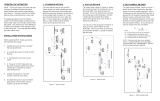
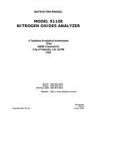
Heated Sample Inlet and Dry Sample Outlet
Run the heated sample inlet line through entry seal and into enclosure and connect the sample tubing to the
compression fitting port labelled “Wet Sample Inlet”. Shrink entry seal tubing around the heated sample line with
a heat gun to provide a water tight seal.
Connect the Readi-GASS system to the sample gas analyzers or downstream sample pump via the port labelled
“Sample Gas Outlet”.
Sample Gas
Outlet
High temperature heated line is not necessary for
Sample outlet connection. However, if the sample
line will be exposed to
Freezing temperatures, freeze protection is
recommended.
Sample Gas
Inlet
Mounting
hole
Entry Seal

Model RG-1024 User’s Manual
Doc. #562: Revision: 004
Page 10 of 29
©2018 Perma Pure LLC. All rights reserved. Specifications subject to change.
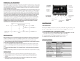
Atmospheric Air Inlet
Atmospheric air enters through a filter attached to outside of the system. It then passes through a smaller filter
inside which allows a visual check of the condition. Both filters have replaceable elements. An optional filter cap
is available for use in installations where atmospheric fog conditions may occur for extended periods of time.
Filter Drain Outlet
Vent the exhaust to a remote location, connect a line to the port labelled “Drain Port”. For runs under 10 ft., ¼”
pipe is acceptable. For runs 10-40 ft., 3/8” pipe is recommended and the number of elbows should be kept to a
minimum. This port must be connected to an appropriate drain that can accept a minimum of 0.25 scfm (7 lpm)
of air with entrained acidic mist.
Atmospheric
Air Inlet
Filter Drain
Outlet
WARNING!
Failure to properly connect this port may result in personal injury and/or property damage! Connect the
line from the filter drain outlet to designated collection/exhaust basin that is capable of accepting acid
mist and the sample gas present at this location.
Atmospheric Air Inlet with optional cap that
functions a fog eliminator. Prevents entrained liquid
water aerosols from entering the system.

Model RG-1024 User’s Manual
Doc. #562: Revision: 004
Page 11 of 29
©2018 Perma Pure LLC. All rights reserved. Specifications subject to change.
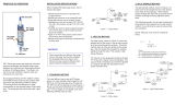
Exhaust vent
Connect tubing or pipe of an appropriate material from port labelled Exhaust Outlet to a permanent vent
designed for this type of discharge. 1/2” I.D. tubing can be used for runs up to 10 feet. Use larger I.D.
tubing for longer exhaust lines. Too small of an ID and/or too long of a piping run may cause inadequate
purge vacuum performance and/or collapse of the dryer membrane tubes resulting in poor drying
performance and/or high sample gas flow restriction.
Failure to properly vent the system may result in personal injury and/or property damage!
The gas exhausted from the purge exhaust port under normal operation is humid air. However, in the event of
an internal failure of the sample gas dryer installed in the system, the exhaust may contain sample gas that
may be hazardous. The purge exhaust must be permanently routed to a vent system or directly outdoors. Do
not allow the purge to vent into a structure or confined space.
Power Connection
Readi-GASS model RG-1024 is intended to be hard wired via a customer supplied mains circuit breaker switch
(MCB) and wire capable of supplying the required current. Check local/regional electrical codes. The external
MCB must be installed in close proximity to the equipment, within easy reach of the operator and shall be clearly
marked as the disconnecting device for the Readi-GASS. Refer to drawing RG-1024-04-01 and connect the AC
power and alarm wires to the terminal block mounted on the inside bottom of the enclosure near the ½” conduit
hub inlet. Adhere to all electrical code requirements in effect at the installation site. Cutting the conductors so
that the ground wire is an inch or two longer than the others, ensures that the protective earth conductor is the
last to take the strain if the wires are pulled.
Power
Connections
Exhaust vent

Model RG-1024 User’s Manual
Doc. #562: Revision: 004
Page 12 of 29
©2018 Perma Pure LLC. All rights reserved. Specifications subject to change.
Alarm Signal Connection
The general alarm relay is de-energized in the alarm state. When both the temperature and the pressure are
above the acceptable minimum level, the alarm relay will be energized. Loss of system power will also trigger an
alarm. The alarm output is in the form of a SPDT (single pole double throw) set of dry contacts.
Alarm Signal
Connections

Model RG-1024 User’s Manual
Doc. #562: Revision: 004
Page 13 of 29
©2018 Perma Pure LLC. All rights reserved. Specifications subject to change.
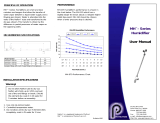
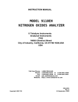
System Component Locations C
Sample Gas Inlet
with Pressure
Snubber Orifice
Particulate Filter
and Bulk Water
Removal
Coalescing Filter
Filter Drain
Eductor
Purge air Dryer
Vacuum Gauge
Dry Sample
Gas Outlet
Temperature
Controller
Purge Flow
Rotameters
Heated Sample
Line Inlet
Purge Air Intake
Filter / Fog
Eliminator
Sample Dryer
Purge Eductor
Regulator
Sample Gas
Dryer Purge
Eductor
Purge Air Intake
Backup Filter
Sample Dryer
Purge Vacuum
Gauge
Purge Air Dryer
Purge Eductor
Regulator
Drain Eductor
Needle Valve
Purge Air Dryer
Purge Eductor
Purge Air Dryer
Purge Flow
Control Valve
Sample Gas
Dryer Purge Flow
Control Valve
Purge Air Dryer
Sample Gas
Dryer
Sample Gas
Isolation Valve
Electrical
Connections
Dryer Purge
Exhaust
Fog Eliminator
Condensate
Outlet

Model RG-1024 User’s Manual
Doc. #562: Revision: 004
Page 14 of 29
©2018 Perma Pure LLC. All rights reserved. Specifications subject to change.
SAMPLE GAS FLOW COMPONENTS
Pressure Snubber (Restriction Orifice)
The pressure snubber, located in the sample gas inlet fitting, slows the buildup of pressure from the external
probe filter blowback air to prevent possible damage to system components. It is located in the sample tube
between the inlet union and the elbow fitting in the inlet port of the lower filter and consists of a short section of
small ID Teflon® tubing.
Sample Gas Filters/Eductor
First, bottom filter – FF-250 with a (0.1 um, 75% efficiency) particulate element removes particles and
provides a liquid collection volume that in the event of a heating failure in upstream components, will
prevent the majority of liquid from reaching the second filter.
Second, top filter – FF-250 with a 0.1 um, 95% efficiency standard coalescing element removes small
particles and prevents liquid water and condensable vapors from passing through the system to the
analyzer.
Consisting of parts machined from solid Kynar® (PVDF) fluoro-polymer, the two filter bodies are designed to hold
different filter elements as mentioned above for the purpose of removing particulate matter and high boiling point
liquids like sulfuric acid. To prevent water from condensing in the filter and causing the possible loss of water
soluble analytes gases, the filter is surrounded by a heated enclosure. The temperature of heated enclosure is
controlled by a temperature controller that is factory set at 70C.
The particulate matter is removed by collection on the filter element and any liquids are removed by first
coalescing on the filter element and then collecting at the bottom of the filter bowl and removed by the drain
system.
Sample Gas Dryer
Removes water vapor from the gas sample stream with high selectivity that prevents loss of the analytes that are
being measured.
Consisting of a PD series 20” Nafion™ membrane dryer and a mounting block assembly surrounded by a heated
enclosure. Its sole purpose is to remove water vapor from the sample gas stream. Drying is accomplished by a
number of small diameter “hollow fibre” tubes extruded from a unique polymer called Nafion™. While essentially
a modified Teflon™ material, Nafion™ retains all of the chemical resistance and inertness of Teflon™ but has
additional properties that allow it to remove water vapor without otherwise altering the gas composition. This
makes Nafion™ the ideal material for drying analytical sample gases. To ensure the water present in the sample
gas remains in the vapor phase, the membrane dryer is mounted in an aluminum block surrounded by a heated
enclosure. The temperature of the heated enclosure is controlled by a temperature controller that is factory set at
70C.
As the sample gas flows through the hollow fibre Nafion™ tubes, the water vapor contained in the sample gas
reacts chemically with the surface of the Nafion™ material. Water vapor is thereby drawn out of the sample gas,
into the walls of the hollow fibre tubes and evaporates into the dry purge air that sweeps across the outside
surface of the tubes.
The sample gas dryer purge air flow rate is controlled by a needle valve located in the purge inlet port. The purge
flow rate and vacuum level can be monitored with the installed rotameter and vacuum gauge.

Model RG-1024 User’s Manual
Doc. #562: Revision: 004
Page 15 of 29
©2018 Perma Pure LLC. All rights reserved. Specifications subject to change.
Sample Isolation Valve
This valve prevents the flow of sample gas if the compressed air pressure is not adequate to allow the system to
function properly.
To generate dry purge air for the sample gas dryer, compressed air of 60-100 Psig must be applied to the
system to generate a sufficient amount of vacuum.
The sample isolation valve is a pneumatically operated on/off valve. It is a normally closed (NC) valve that once
compressed air of greater than approximately 40 psig is applied to the Readi-GASS, opens and allows the
sample gas to pass through the system
Filter Drain System
Since the Readi-GASS system is typically located upstream of the sample pump, the sample gas in the system
is under slight vacuum. In order to remove any liquid collected in the filter, a vacuum higher than the vacuum
inside the filter is required. This high vacuum is achieved by an eductor (venturi). Compressed air is supplied to
this eductor via a needle valve which then generates the required vacuum, Liquids, including coalesced acid
mist, collected at bottom of the filter bowl are pulled through the metering tube by the drain eductor. Extraction of
the collected liquid from the filter is continuous.

Model RG-1024 User’s Manual
Doc. #562: Revision: 004
Page 16 of 29
©2018 Perma Pure LLC. All rights reserved. Specifications subject to change.
PURGE AIR FLOW COMPONENTS
Purge Air Filters
Atmospheric air enters through a filter attached to outside of the system. It then passes through a smaller filter
inside which allows a visual check of the condition. Both filters have replaceable elements.
Fog Eliminator – An optional cap for the air inlet filter prevents entrained water droplets from atmospheric fog
from entering the system. It should be used whenever the system is installed in an area where may occur.
Purge Gas Dryer
Removes water vapor from the incoming atmospheric air and is used to purge both itself and the sample gas
dryer.
Consisting of a PD series, 12” Nafion™ membrane dryer with reflux purge mode. Its sole purpose is to remove
water vapor from the ambient air.
As the air flows through the hollow fibre Nafion™ tubes, the water vapor contained in the ambient air reacts
chemically with the surface of the Nafion™ material. Water vapor is thereby drawn out of the ambient air, into the
walls of the hollow fibre tubes which evaporates into the dry purge air that sweeps across the outside surface of
the tubes.
The purge air dryer’s purge air flow rate is controlled by a needle valve located in the purge dryer’s purge inlet
port. The purge air exhaust is connected to the eductor suction port. The purge flow rate and vacuum level can
be monitored with the installed rotameter and vacuum gauge.
Flowmeters and Needle Valves
For maximum drying performance, monitor the flow of purge gas through the two PD dryers.
Purge dryer purge air flowrate – 2.0 LPM
Sample dryer purge air flowrate – 5.0 LPM
Vacuum Gauges
For optimal drying performance, monitor the vacuum levels generated to purge the PD dryers.
Purge dryer purge air vacuum – 23.6 in-hg
Sample dryer purge air vacuum – 20.9 in-hg
Eductors
Generate the vacuum required to purge the PD dryers.

Model RG-1024 User’s Manual
Doc. #562: Revision: 004
Page 17 of 29
©2018 Perma Pure LLC. All rights reserved. Specifications subject to change.
COMPRESSED AIR FLOW COMPONENTS
Pressure Regulators
Controls the pressure to the three eductors to allow for vacuum level adjustment.
Drain Eductor Needle Valve
Further restricts the compressed air flow to the drain eductor to allow for fine tuning of the drain eductor vacuum
level.

Model RG-1024 User’s Manual
Doc. #562: Revision: 004
Page 18 of 29
©2018 Perma Pure LLC. All rights reserved. Specifications subject to change.
ELECTRONIC CONTROL AND INSTRUMENTATION COMPONENTS
Temperature Controller
Maintains specified temperature in the heated zone by use of PID style controller.
Two 40w silicone pad heaters mounted on heated zone back plate, behind the filters.
One 35w heater mounted in the dryer mounting block
Temperature is monitored by a thermocouple in the dryer mounting block.
Alarm Relay
The general alarm relay is de-energized in the alarm state. When both the temperature and the pressure are
above the acceptable minimum level, the alarm relay will be energized. The alarm relay is configured in this way
to allow the loss of system power to also trigger an alarm. The alarm output is in the form of a SPDT (Single Pole
Double Throw) set of dry contacts.
Low Temperature Alarm Relay
Relay contacts inside the temperature controller are open when the temperature is more than 10C
below the set point temperature. This causes the general alarm relay to de-energize (In the alarm state
the general alarm relay is de-energized).
Low Compressed Air Pressure Alarm Switch
Switch contacts are open when the pressure is below ~55 psig (3.8 barg) and causes the general alarm
relay to de-energize (In the alarm state the general alarm relay is de-energized).
System Power Fail Alarm
The alarm relay is de-energized in the alarm state which means that the loss of AC power will also put
the alarm relay into the alarm state.
Thermal Insulation
Heated zone is insulated with ½” foam rubber insulation. The dryer shell inside the heated zone is insulated with
½” foam rubber insulation to prevent overheating of the dryer.

Model RG-1024 User’s Manual
Doc. #562: Revision: 004
Page 19 of 29
©2018 Perma Pure LLC. All rights reserved. Specifications subject to change.
SYSTEMS OPERATION MONITORING
The temperature controller and Pressure switch monitors the system parameters like temperature of the heated
enclosure (70C) and compressed air Pressure (>55 Psig) for proper operation and can alert personnel of
potential problems via an indicator light signal (alarm red LED On front panel) and external control system via
digital outputs (Potential free Contact), (SPDT Relay, 3 A, 250 VAC (De-energized in Alarm state).
A. Alarm Output Operation
The system has only one digital alarm output. It can be used to signal an external control system (PLC)
that a problem has been detected. The definition of an active alarm is that the SPDT relay will be OFF
(de-energized). During normal operation, (i.e. no active alarms), the alarm relay coil will be on
(energized). In the event of a power failure to the system, alarms will also be in the active or de-
energized state. The SPDT relay is of 3 A, 250 VAC. Customer can use same contact for their use.
General Alarm Relay and Indicator Light – This is an alarm that is initiated by either of the two alarms
described below. At any time while the system power is on and either of the two alarms above, low
temperature or low pressure, is active, this alarm will also be active.
This Alarm has a series connection of low temperature condition and low compressed air pressure
condition
Low Temperature Alarm – This alarm is initiated when heated enclosure temperatures fall below the
respective set point by 10C as sensed by the thermocouples. At any time the system temperatures is
too low, this alarm will be activated.
Low Compressed Air Pressure Condition – This occurs when the compressed air pressure that is
used to generate vacuum, open the sample isolation valve, and purge the membrane dryer, is too low.
The compressed air pressure is sensed by a pressure switch located in the lower enclosure. At any time
while the compressed air pressure is too low (<55 Psig), the general alarm will be active. Additionally,
the sample isolation valve will close.
B. System Power Indicator
The system power yellow Indicator light serves as a basic system status indicator and is located on front
panel. If the system has incoming AC Power, the indicator light will be lit. If no AC power is present, the
indicator will not light.

Model RG-1024 User’s Manual
Doc. #562: Revision: 004
Page 20 of 29
©2018 Perma Pure LLC. All rights reserved. Specifications subject to change.
START-UP PROCEDURE
(Readi-GASS commissioning/troubleshooting kit req’d)
Read through Start-up check completely before energizing system.
Primary Sample Handling System Check Procedure
Check that heated probe and heated line are working properly and maintaining desired temperature.
Heated probe filter element (typically 2 micron) should be cleaned frequently and replaced if required.
Check for cold spots (unheated tubing) in the heat traced sample line is always recommended upstream
of the Readi-GASS System. Sample should enter Readi-GASS system above 100C.
Blowback air operated valve or SOV functioning needs to be checked.
Readi-GASS System Check Procedure
Check that the electrical, compressed air, sample gas inlet and outlet, and purge exhaust/filter drain connections
have been made and that the proper voltage, pressures, etc. are present. All operating parameters are pre-set
and the system is fully tested at the factory. However, shipping and handling of the unit may have affected some
of the settings so an initial check is important.
With the enclosure cover off, follow below procedure:
Note: The enclosure cover must be reinstalled before operation.
Turn on compressed air to the system (60-100 Psig). Air will begin exhausting from the vent port. If the
airflow is absent check for proper compressed air pressure at the inlet to the system.
Flowmeters and Needle valves
Confirm the flow of purge gas through the two PD dryers.
Purge dryer purge air flowrate – 2.0 LPM
Sample dryer purge air flowrate – 5.0 LPM
Vacuum gauges
Monitor the vacuum levels generated to purge the PD dryers
Purge dryer purge air vacuum – 23.6 in-hg
Sample dryer purge air vacuum – 20.9 in-hg
Turn on power to the system, and check that the display on the temperature controller turns on and the
yellow indicator on the front panel/cover is on. Install the enclosure cover.
Allow the system to heat for about 30 minutes for the system temperature to reach the factory default set
point of 70C.
The red alarm indicator light will turn off when adequate compressed air pressure is present and system
temperature has reached a minimum temperature of set point minus 10C.
The Readi-GASS system is now ready for service.
/