Page is loading ...

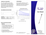
Figure 1 - Typical Setup
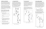
2. REFLUX METHOD
The reux setup, shown in Figure 2, returns dry
sample back to the dryer for use as the purge
after it has gone through the analyzer. Since
this method uses all of the dry sample as the
purge gas, only the sample ow required for
analysis passes through the dryer. This results
in high drying efciency.
The vacuum on the purge gas should be at least
15” of Hg, with a higher vacuum preferable.
This vacuum level is necessary to provide the
desired 2:1 purge-to-sample ow ratio based on
the actual volumetric ow.
Figure 2 - Reux Setup
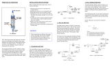
The split sample method, shown in Figure
3, diverts some of the sample from the
main stream to be used as the purge gas.
More sample passes through the dryer
than is required for the analysis, lowering
the drying efciency somewhat.
The following equation can be used to
determine the purge ow rate required for
the split sample method. Any units may be
used as long as they are consistent.
NOTE: Pressure units must be in absolute
terms.
Vp = Vs
(Ps/1.05Pv) - 1
Where:
Vp = Purge owrate (indicated on owmeter)
Vs = Sample owrate (indicated on owmeter)
Ps = Sample pressure (in absolute units)
Pv = Purge pressure (in absolute units)
Figure 3 - Split Sample Setup
INSTALLATION SPECIFICATIONS
1. STANDARD METHOD 3. SPLIT SAMPLE METHODPRINCIPLE OF OPERATION
MD™-Series gas dryers are shell and tube
moisture exchangers that transfer water
vapor between two countercurrent owing
gas streams. The dryers consist of a Naon®
polymer tube surrounded by an outer tube.
Dry purge gas owing over the exterior
surface of the Naon tubing continuously ex-
tracts water vapor from the gas stream inside
the tubing. The driving force is the difference
in water concentration on the opposite sides
of the tubing wall. The purge gas then carries
the water vapor away.
The most efcient way to set up MD-Series
dryers is to have sample enter through the
Naon tube (wet sample inlet) and purge
gas owing countercurrent to the sample
(refer to Figure 1). Purge gas should be
instrument air or other dry gas. If no dry
purge air is available, one of the following
methods may be used.
When installing MD-Series gas dryers, the
following rules apply:
1. Sample pressure equal to or greater than
purge pressure
2. Sample gas pressure not to exceed 80
psig
3. Temperatures must not exceed 120°C
4. Purge air of -40°C dew point at a ow rate
of two to three times sample ow
5. Sample and purge air must ow count-
er-current to each other
6. If sample dew point is above ambient
temperature, inlet of dryer must be heated
(contact factory for details)
Adjusting end ttings without following the
steps on the back page will cause twist-
ing of the membrane tubing and void the
warranty.
WARNING!
EXHAUST
VACUUM PUMP
NEEDLE
VALVE
VACUUM GAUGE
GAS
ANALYZER
FLOW
METER
DRY
SAMPLE
OUTLET
WET
SAMPLE
INLET
MD DRYER
EXHAUST
VACUUM PUMP
VACUUM GAUGE
GAS
ANALYZER
DRY
SAMPLE
OUTLET
WET
SAMPLE
INLET
PUMP
(OPTIONAL)
(OPTIONAL)
PURGE
AIR
FLOW
METER
NEEDLE
VALVE
SAMPLE
FLOW
METER
NEEDLE
VALVE
PRESSURE
GAUGE
EXHAUST
MD DRYER
NEEDLE
VALVE
GAS
ANALYZER
MD DRYER
FLOW
METER
DRY
SAMPLE
OUTLET
WET
SAMPLE
INLET
INSTRUMENT
AIR
INLET
DRY
SAMPLE
EXHAUST
PURGE
EXHAUST
PRESSURE
REGULATOR

Tools Needed:
- Two wrenches - 5/8 and 7/16
- Tweezers
Refer to Figure 4
1. Hold tee tting with appropriate wrench
above and loosen union tting with
additional wrench.
2. Remove tting.
3. Rotate dryer element 10 degrees each way
with tweezers or ngertips.
4. With two wrenches, loosen inside nut con-
necting tee tting to shell tube.
5. Rotate tee tting to desired location and
tighten into place.
6. Install union into tee tting while making
sure element is not pushed back out of
o-ring seal. Take caution to ensure ele-
ment does not rotate inside shell.
7. Tighten union tting by hand and then
tighten 1/4 turn with wrench.
Tools Needed:
- Two wrenches - 5/8 and 7/16
- Pair of lightweight gloves
1. Repeat steps 1-4 for other end.
2. Put on lightweight gloves to protect
membrane tubing
(skin oils can contaminate surface).
3. Gently push one end of element out of
o-ring while pulling other end out of tee
tting.
4. Gently pull element out of housing
from opposite end.
5. Reverse for reassembly. Element
ends should extend equally from each
end of shell housing before installing
union ttings.
TO ROTATE FITTINGS
Figure 4
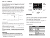
PERFORMANCE
Performance Curves
TO DISASSEMBLE DRYER
MD-Series dryer’s performance varies according to
dryer lengths, ow rates and length of Naon tubes.
-10
-5
0
5
10
4
3
21
0
-15
-20
-25
MD-110 DRYING PERFORMANCE
MD-110-12
MD-110-24
MD-110-72
MD-110-96
MD-110-144
-50
-40
DEWPOINT ( C)
-30
0100 200
0
-10
-20
20 40 60 80 120 140 160 180
MD-110-48
-60
FLOWRATE (CC/MIN.)
DEWPOINT ( C)
MD-050 DRYING PERFORMANCE
FLOWRATE (L/MIN.)
MD-050-12
MD-050-24
MD-050-48
MD-050-72
FLOWRATE (L/MIN.)
DEWPOINT ( C)
MD-070-144
MD-070-96
MD-070-72
MD-070-48
MD-070-24
MD-070-12
-25
-20
-15
01234
10
5
0
-5
-10
MD-070 DRYING PERFORMANCE
When connecting sample line to dryer, hold
union tting with a wrench before tightening the
compression nut. Failure to do so may over-
tighten the union connector tting, twist dryer
membrane and damage the dryer.
Tee Fitting
Union Fitting O-Ring
Element
Nut
Tee Fitting
Union Fitting
O-Ring
Element
Nut
Inside Nut
Inside Nut
1001 New Hampshire Ave, Lakewood, N.J. 08701
Phone: 732-244-0010 Fax: 732-244-8140
[email protected] www.permapure.com
PERMA PURE
MD™ -Series
Gas Dryer
User Manual
WARNING!
Naon® is a registered trademark of DuPont
PD™ is a trademark of Perma Pure LLC.
DOC # MD-MAN-001 REV 00
/