ICM Controls ICM104 Application/Install Guide
- Type
- Application/Install Guide

• Knob adjustable from 10-1,000 seconds
• 18-30 VAC/VDC, up to 240 VAC load
INSTALLATIONMODE OF OPERATION
1. Disconnect power.
2. Connect terminals as shown in the
wiring diagram below.
3. Select the desired time delay.
4. Reapply power, check operation.
When power is applied to the input, the
time delay begins. After the time delay is
complete, the load energizes and remains
energized as long as power is applied. The
control is reset by removing power during or
after the time delay period.
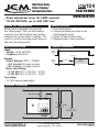
WIRING DIAGRAM
Thermostat
T2 T1
NCNO
COM
Contacts internal to relay
SF PF
R
PS
24 VAC
Input
120-240 VAC
C
SS
SPECIFICATIONS
Input
• Voltage: 18-30 VAC/VDC
• Frequency: 50-60 Hz
Output
• Output Ratings: SPDT 1 FORM C
– N.O. Contact: 20 amps resistive
– N.C. Contact: 10 amps resistive
• Motor Load Rating:
– @ 120 VAC: N.O., 2 HP, N.C., 1/2 HP
– @ 240 VAC: N.O., 2 HP, N.C., 1/2 HP
Time Delay
• 10-1,000 seconds adjustable
TIMING DIAGRAM
0V
Load
Voltage
0V
Input
Voltage
Transfer
Load
Energized
Time Delay
Time
Time
7313 William Barry Blvd.
North Syracuse, NY 13212
ICM CONTROLS 800.365.5525
www.icmcontrols.com LII013-1
ICM104
DELAY ON MAKE
HMVR24A2X1000
High Power Relay
Output, Staging/
Startup Delay Timer
-
 1
1

ICM Controls ICM104 Application/Install Guide
- Type
- Application/Install Guide
Ask a question and I''ll find the answer in the document
Finding information in a document is now easier with AI
Related papers
Other documents
-
 Xantrex SW Plus 4048 User manual
-
Eaton Cutler-Hammer D64RP18 User manual
-
Johnson Controls IFC-3030 Installation guide
-
-
Carrier GAS FURNACE 58MVP User manual
-
-
 Xantrex SW Series 2512 & 4024 Owner's manual
-
Xantrex Technology Trace SW2612A User manual
-
-
Alfa Laval 762-227MRAL User manual

