Page is loading ...

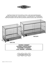
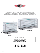
The catering program
Production code: OASI 8M BM/LUX
Mod: OASI 8M BM/LUX
08/2005

Operator's guide:
1. Unpacking instructions
2. Opening the protective cover
3. Cleaning the internal basin
4. Cleaning the cover and external parts
5. Holders for containers
6. Plate-holder
7. Filling and emptying the basin
8. Connection to the mains
9. Controls
10. Checking correct operation
Maintenance manual (Page 48):
4. Wiring diagram diagram of refrigeration unit
1. Cleaning the bain-marie basin
2. Replacement of the lamps
3. Replacement of the cover's lifting motor
!
I
UK
D
E
F
NL
P
S
DK
FIN
B
GR
CZ
EE
LV
LT
H
M
PL
SK
SLO
6
Operator's guide
WARNINGS
It is most important that this instruction booklet is kept together with the appliance both for future
reference and for reasons of safety.
1. Adults should operate this appliance only. Do not allow children to use the controls or play with it. 2
3
4
5
6
7
.It
is forbidden to modify in any way the main functions and characteristics of this appliance. . The electrical
installation of the appliance should be carried out by a qualified electrician or other competent person.
. Never attempt to carry out repairs unassisted. Inexpert repairs can cause serious damage and
malfunction. . Assistance has to be provided by an authorized engineer only. Always use original spare
parts. . This appliance is not suitable for the storage of basic commodities not including food-stuffs.
. The manufacturers of this appliance accept no responsibility for the consequences of misuse in
contravention of these safety instructions. It further reserves the right to carry out improvements without
prior notice.89
10
11
12
13
. Avoid installing the cabinet directly in line with sunlight. . Nevere install the appliance near
sources of heat, such as radiators, stoves, etc. . Keep the ventilation grills free from obstruction for at
least 30 cm. .Ensure that the products displayed on the shelves and grills do not hang over the edges.
. If damp air or products to be refrigerated should cause ice to form on the evaporator, we recommend
stopping the compressor and placing the goods in special refrigerated containers, kept at the same
temperature, until defrosting is completed;if this is not carried out the compressor will continue to operate
leading to a wasteful consumption of electricity and poor performance. . If the appliance is not working
and unused, it is indispensable to keep the door open at least 10 cm.
1. UNPACKING INSTRUCTIONS
CARDBOARD BOXES 1a
WOODEN CRATES 1b. . 2
34 5.
6
78
2. OPENING THE PROTECTIVE COVER
1 2
(A)
3. CLEANING THE INTERNAL BASIN
12.
3. (A) (B).
4.
4. CLEANING THE COVER AND EXTERNAL PARTS
1.
2. 3.
4
5. HOLDERS FOR CONTAINERS
1. 2.
3.
6. PLATE-HOLDER M LUX
. Cut surrounding tape. Remove the cardboard package by sliding it upwards.
Remove the nails from the wooden crate with care . Insert forks of forklift truck
between the appliance and pallet or crate. . Lift the appliance. . Remove the pallet or crate. Place
the appliance on a flat, level surface. . Make sure there is nothing left in the package before disposing of
it. . Sort out the packaging materials in order to facilitate disposal. . The appliance can be locked in
place by engaging the wheel brakes (see fig. 1).
. Plug the machine into the power supply socket, as described in Chapter 8. . Turn the switch of the
electric lifting system to position II until the cover is fully open (see fig. 2).
. Remove the protective film from the stainless steel parts. Clean the basin with a soft sponge and
neutral detergents. Remove obstructions in front of the float hole and the drainage hole
Open the tap located on one of the machine's sides to drain any residual water (see fig. 3).
Never use detergents containing alcohol or solvents which would irremediably damage the cover,
compromising its transparency. Use only a soft damp sponge. As far as the wooden surfaces are
concerned, use proprietary detergents especially designed for wooden surfaces, which are water-based
and do not contain solvents. . Dry with a clean cloth.
Remove the protective film from the holders. Place the intermediate holders in the slots on the
transverse holders. Different arrangements are available for different container sizes and positions.
Position the containers in accordance to your requirements (see fig. 4).
Fasten the shelves to the outer cabinet, by tightening the screws inside the holes provided for this
purpose (see fig. 5).
version

I
UK
D
E
F
NL
P
S
DK
FIN
B
GR
CZ
EE
LV
LT
H
M
PL
SK
SLO
7
Operator's guide
7. FILLING AND EMPTYING THE BASIN
1.
2
3.
8. CONNECTION TO THE MAINS
1 (A)
2
3
4.
5
9. CONTROLS
1. Thermostat:
2. Basin resistor switch: 3. Heating
lamp switch: 4. Energy-regulator:
5. Cover lifting switch:
6. Light switch: 7. Water level alarm:
10. CHECKING CORRECT OPERATION
Make sure that: 1. 2 3
45 6.
78.
The basin must be filled manually, taking care not to fill above the level indicated on the basin walls.
. The machine gives an acoustic warning signal to advise you when water must be added to the basin.
To empty the basin, open the tap fitted on one of the machine's sides.
. Ensure that mains voltage and frequency are the same as those stated on the rating plate attached
to the appliance. . Ensure that the supply socket:
. Ensure that there is no danger of explosion (AD) in the
room. Make sure the environment is suitable for the power supply cable provided. The cable of the
appliance is H05 VVF, designed for internal use. For installation in other than internal settings, it will be
necessary to replace the cable with the appropriate type (for example H07 VVF for external settings).
. Insert the plug in the socket. The machine is not supplied with a plug. Provide the power supply cable
with a plug fulfilling the power requirements indicated on the rating plate (do not use three-way adapters
and reduction adapters) (see fig. 6).
The appliance features controls situated in a protected panel. to adjust the temperature in
the appliance. to switch on the resistors of the bain-marie basin.
to switch on the heating lamps. to adjust the intensity of the heating
lamps. to open and close the cover - Position II to lift - Position O to stop -
Position I to lower. to turn on the internal light. signalling when
water must be added (see fig. 7).
the plug is connected; . cover is open; . bain-marie resistor switch is on (green
light lit up); . heating lamps are on; . water level in the bain-marie basin is within the limits. Remove
any obstructions in front of the float hole. . Check that the set temperature is correct. Keep the
machine away from inflammable material or any danger of explosion.
a) b)
c)
is properly earthed; fulfils the requirements of the
rated current as set out on the rating plate; complies with the IEC regulations:- differential thermal-
magnetic switch (also known as ground fault interrupter) with In = rated value as stated on the rating
plate; - differential with Id sensitivity = 30 mA.

I
UK
D
E
F
NL
P
S
DK
FIN
B
GR
CZ
EE
LV
LT
H
M
PL
SK
SLO
I
UK
D
48
1. PULIZIA DELLA VASCA BAGNOMARIA
1
2
2. SOSTITUZIONE DELLE LAMPADE
Attenzione:
12.
34
LAMPADE AD INFRAROSSI 5
67.
8
9 10.
LAMPADE D’ILLUMINAZIONE AD INCANDESCENZA 11.
12
. Togliere l’alimentazione elettrica, agendo sull’interruttore generale e sfilando la spina dalla presa.
.
Prima di effettuare una qualsiasi operazione sulle lampade attendere che tutti i componenti si
siano raffreddati. . Aprire la cupola normalmente. Togliere l’alimentazione come descritto nel Capitolo
1. . Svitare le viti sul lato del coperchio. . Sollevare il coperchio della plafoniera per aver accesso ai
gruppi lampade. . Svitare, dall’esterno, le viti di fissaggio del corpo
lampada. . Svitare le viti di fissaggio della parabola, asportandola. Togliere le pipe alle estremità della
lampada. . Svitare i bulloncini che fissano i contatti elettrici alle due estremità della lampada ad infrarossi.
. Sfilare la lampada ad infrarossi dalla sua sede e sostituirla con una originale Tecfrigo. Ripristinare il
tutto procedendo in senso inverso. Svitare la
lampada ad incandescenza e sostituirla con una nuova. . Ripristinare il tutto procedendo in senso
inverso
Aprire il rubinetto posto su un lato della macchina. . Pulire le pareti della vasca con spugna morbida
inumidita con acqua o detergenti neutri. . Asciugare tutto con cura usando un panno morbido e pulito.
. Chiudere il rubinetto della vasca e ripristinare l’alimentazione elettrica
(Vedi Fig. 1).
. Togliere l'alimentazione elettrica. . Scollegare il motoriduttore dall'alimentatore. . Togliere le viti di
fissaggio del vassoio superiore e rimuoverlo assieme alla cupola. . Liberare la staffa di sollevamento e
abbassare la parte mobile della guida. . Sfilare verso l'alto il motoriduttore. . Posizionare e bloccare le
piastrine di fissaggio sul nuovo motoriduttore. . Rimontare il tutto procedendo in senso inverso(Fig.2)
3
4
5
3. SOSTITUZIONE DEL MOTORE DI SOLLEVAMENTO DELLA CUPOLA
12 3
4
56
7
1. CLEANING THE BAIN-MARIE BASIN
12
3. 4
5
2. REPLACEMENT OF THE LAMPS
Warning:
12 3
4. INFRARED LAMPS
56
7. 8
9
10
INCANDESCENT LAMPS 11
12.
3. REPLACEMENT OF THE COVER'S LIFTING MOTOR
1. 2 3
4.
56.
7
. Turn off the power switch and pull the plug out of its socket. . Open the tap on one of the machine's
sides. Clean the basin walls with a sponge dipped in water or neutral detergents. . Carefully dry each
item with a dry, clean cloth. . Turn the tap off and reconnect the appliance to the power supply.
before attempting to carry out any operation on the lamps, wait for all components to cool down.
. Open the cover. . Turn the appliance off, as described in Chapter 1. . Loosen the screws on the side
of the cover. Lift the cover of the ceiling lamp to gain access to the lamp units.
. From the outside, loosen the screws fastening the lamp unit. . Loosen the screws holding the parabola
in place and remove it. Remove the attachment plugs at the ends of the lamp. . Loosen the bolts that
fix the electrical contacts to the two ends of the infrared lamp. . Remove the infrared lamp from its seat
and replace it with a new original Tecfrigo one. . Refit all parts by following the above instructions in
reverse order. . Unscrew the incandescent lamp and replace it with a new
one. Refit all parts by following the above instructions in reverse order (see fig. 1).
Turn the appliance off. . Disconnect the gear motor from the power supply unit. . Remove the screws
fastening the top tray in place and remove the tray along with the protective cover. Release the lifting
bracket and lower the mobile part of the guide. . Pull the gear motor out. Position and fasten the fixing
plaques onto the new gear motor. . Refit all parts by following the above instructions in reverse order
(see fig. 2).
1. REINIGUNG DER WASSERBADWANNE
1.
23.
4. 5
2. AUSTAUSCH DER LAMPEN
Achtung:
12
3. 4
INFRAROTLAMPE 5
6.
7. 8.
9.
10.
BELEUCHTUNGSGLÜHLAMPEN 11
12
3. AUSTAUSCH DES HUBMOTORS DER KUPPEL
1. 2. . 3
4
5.
6. 7.
Schalten Sie den Strom ab, indem Sie den Hauptschalter betätigen und den Stecker aus der Steckdose
ziehen. . Öffnen Sie den Hahn, der sich auf einer Seite der Maschine befindet. Reinigen Sie die
Wannenwände mit einem weichen, mit Wasser befeuchteten Schwamm und neutralen Reinigungsmitteln.
Trocknen Sie alles sorgfältig mit einem weichen und sauberen Tuch ab. . Schließen Sie den
Wannenhahn und stellen Sie die Stromversorgung wieder her.
Bevor sie irgendeinen Eingriff an den Lampen vornehmen, warten Sie, bis alle Bestandteile
abgekühlt sind. . Die Kuppel auf normale Weise öffnen. . Strom wie im Kapitel 1 beschrieben
abschalten. Die Schrauben auf der Deckelseite lösen. . Den Deckel der Deckenleuchte anheben, um
zu den Lampengruppen Zugang zu erhalten. . Lösen Sie von außen die
Befestigungsschrauben des Lampenkörpers. Lösen Sie die Befestigungsschrauben der Parabel und
nehmen Sie sie heraus. Entfernen Sie die Stecker an den Lampenenden. Losen Sie die
Schräubchen, mit denen die elektrischen Kontakte an den beiden Extremitäten der Infrarotlampe befestigt
sind. Ziehen Sie die Infrarotlampe aus ihrem Sitz und ersetzen Sie sie durch eine Tecfrigo-
Originallampe. Alles in umgekehrter Reihenfolge wieder zusammensetzen.
. Schrauben Sie die Glühlampe heraus und ersetzen Sie sie durch
eine neue. . Alles in umgekehrter Reihenfolge wieder zusammensetzen (siehe Abb. 1).
Strom wie abschalten. Den Motorinduktor von der Speiseleitung trennen . Lösen Sie die
Befestigungsschrauben des oberen Tabletts und entfernen Sie es zusammen mit der Kuppel. . Befreien
Sie die Stützbügel und senken Sie den beweglichen Teil der Führung ab. Ziehen Sie den Motorinduktor
nach oben heraus. Positionieren Sie die Befestigungsbleche auf dem neuen Motorinduktor. Alles in
umgekehrter Reihenfolge wieder einsetzen. (Siehe Abbildung 2).

NL
I
E
UK
D
F
1) 2) 3) 4) 5) 6)
7) 8) 9) 10) 11) 12) 13)
14) 15) 16)
Alimentatore Cicalino allarme livello Comando cupola Galleggiante Interruttore Interruttore
Lampade Lampade IR Morsettiera Motoriduttore Relè Resistenze Spina
Termostato Simmostato lampade IR Interruttore
1) 2) 3) 4) 5) 6) 7) 8)
9) 10) 11) 12) 13) 14) 15)
16)
Power supply unit Level alarm buzzer Cover control Float Switch Switch Lamps IR
lamps Terminal board Motor reducer Relay Resistor Plug Thermostat IR lamp
energy regulator Switch
1) 2) 3) 4) 5) 6) 7)
8) 9) 10) 11) 12) 13)
14) 15) 16)
Netzteil Summer Pegelalarm Steuerung Kuppel Schwimmer Schalter Schalter Lampen
IR-Lampen Klemmleiste Getriebemotor Relais Widerstand Netzsteckdose
Thermostat Energieregler IR-Lampen Schalter
1) 2) 3) 4) 5) 6) 7)
8) 9) 10) 11) 12) 13)
14) 15) 16)
Alimentador Alarma de nivel Mando campana Flotador Interruptor Interruptor Lámparas
Lámparas IR Caja de bornes Motorreductor Relè Resistencia Enchufe
Termostato Regulador lámparas IR Interruptor
1) 2) 3) 4) 5)
6) 7) 8) 9) 10) 11) 12) 13)
14) 15) 16)
Alimentateur Vibreur sonore alarme niveau Commande vitrine bombée Flotteur Interrupteur
Interrupteur Lampes Lampes IR Bornier Motoréducteur Relais Résistance Prise
de courant Thermostat Régulateur d'énergie lampes IR Interrupteur
1) 2) 3) 4) 5) 6)
7) 8) 9) 10) 11) 12) 13)
14) 15) 16)
Toevoerleiding Zoemer peilalarm Bediening koepel Vlotter Schakelaar Schakelaar
lampen IR lampen Klemmenbord Reductiemotor Relais Weerstand Stekker
Thermostaat Energieregelaar IR lampen Schakelaar
1) 2) 3) 4) 5)
6) 7) 8) 9) 10) 11)
12) 13) 14) 15) 16)
Alimentador Sin. acústico alarme de nível Comando da cúpula Flutuador Interruptor
Interruptor Lâmpadas Lâmpadas IR Terminal de bornes Motorredutor Relè
Resistência Placa de união Termostato Regulador das lâmpadas IR Interruptor
P
I
UK
D
E
F
NL
P
S
DK
FIN
B
GR
CZ
EE
LV
LT
H
M
PL
SK
SLO
57
/


