Page is loading ...

The catering program
Production code: ISOLA 4-6 M-M LUX GOURMET 4-6M-M LUX
Mod: ISOLA 4-6 M-M LUX
GOURMET 4-6M-M LUX
08/2005

Italiano
English
Deutsch
Español
Français
Nederlands
Português
Svenska
Dansk
Suomi
Vlaams
Ellinika
e tina
Esti keel
Latvie u valoda
Lietuvi kalba
Magyar
Malti
Polski
Sloven ina
Sloven ina
Čš
š
ų
č
šč
INSTALLAZIONE E USO
INSTALLATION AND USE
ZUSAMMENBAU
UND BETRIEB
INSTALACIÓN Y USO
INSTALLATION ET
MODE D'EMPLOI
INSTALLATIE EN GEBRUIK
INSTALAÇÃO E USO
INSTALLATION OCH BRUK
INSTALLATIONS OG
BETJENINGS
ASENNUS JA KÄYTTÖ
INSTALLATIE EN GEBRUIK
INSTALACE A POUŽITÍ
UN
INSTALACIJA IN UPORABA
PAIGALDAMINE JA
KASUTAMINE
BEÉPÍTÉS ÉS HASZNÁLAT
INŠTALÁCIA A POUŽITIE
INSTALACJA I
UZYTKOWANIE
ISTALLAZJONI U UżU
INSTALIAVIMAS IR
NAUDOJIMAS
MANUTENZIONE
MAINTENANCE
INSTANDHALTUNG
MANTENIMIENTO
ENTRETIEN
ONDERHOUD
MANUTENÇÃO
UNDERHÅLL
VEDLIGEHOLDEL-
SESANVISNING
HUOLTO-OHJEET
ONDERHOUD
ÚDRŽBA
APKOPE
VZDRŽEVANJE
HOOLDUS
KARBANTARTÁS
ÚDRŽBA
KONSERWACJA
MANUTENZJONI
TECHNINIS APTARNAVIMAS
ÔÏÐÏÈÅÔÇÓÇ ÊÁÉ ×ÑÇÓÇ
ÓÕÍÔÇÑÇÓÇ
UZSTĀDĪŠANA
EKSPLUATĀCIJA
I
UK
D
E
F
NL
P
S
DK
FIN
B
GR
CZ
EE
LV
LT
H
M
PL
SK
SLO
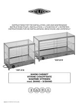
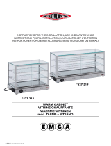
ISOLA 4 -6 M
ISOLA 4-6MLUX
GOURMET4-6M
GOURMET4-6 MLUX

Operator's guide:
1)Unpacking instructions
2)Opening the protective cover
3)Cleaning the internal basin
4)Cleaning the cover and external parts
5)Holders for containers and pastry shelves
6)Support shelves
7)Connection to the mains
8)Controls
9)Checking correct operation
10)Internal and evaporator cleaning
2)Replacement of the lamp
3)Access to the motor compartment
4)Replacement of the cover's lifting motor
Maintenance manual (Page 48):
1)Cleaning the condenser
5)Wiring diagram diagram of refrigeration unit
!
I
UK
D
E
F
NL
P
S
DK
FIN
B
GR
CZ
EE
LV
LT
H
M
PL
SK
SLO
6
Operator's guide
WARNINGS
It is most important that this instruction booklet is kept together with the appliance both for future
reference and for reasons of safety.
1. Adults should operate this appliance only. Do not allow children to use the controls or play with it. 2
3
4
5
6
7
.It
is forbidden to modify in any way the main functions and characteristics of this appliance. . The electrical
installation of the appliance should be carried out by a qualified electrician or other competent person.
. Never attempt to carry out repairs unassisted. Inexpert repairs can cause serious damage and
malfunction. . Assistance has to be provided by an authorized engineer only. Always use original spare
parts. . This appliance is not suitable for the storage of basic commodities not including food-stuffs.
. The manufacturers of this appliance accept no responsibility for the consequences of misuse in
contravention of these safety instructions. It further reserves the right to carry out improvements without
prior notice.89
10
11
12
13
. Avoid installing the cabinet directly in line with sunlight. . Nevere install the appliance near
sources of heat, such as radiators, stoves, etc. . Keep the ventilation grills free from obstruction for at
least 30 cm. .Ensure that the products displayed on the shelves and grills do not hang over the edges.
. If damp air or products to be refrigerated should cause ice to form on the evaporator, we recommend
stopping the compressor and placing the goods in special refrigerated containers, kept at the same
temperature, until defrosting is completed;if this is not carried out the compressor will continue to operate
leading to a wasteful consumption of electricity and poor performance. . If the appliance is not working
and unused, it is indispensable to keep the door open at least 10 cm.
1. UNPACKING INSTRUCTIONS
CARDBOARD BOXES 1a.
WOODEN CRATE 1b. 2
3. 4. 5
6.
78
2. OPENING THE PROTECTIVE COVER
1. 2
3. CLEANING THE INTERNAL BASIN
12
3
4. CLEANING THE COVER AND EXTERNAL PARTS
1.
23
4
5. HOLDERS FOR CONTAINERS AND PASTRY SHELVES
12
3
4.
.5.
6. SUPPORT SHELVES
M LUX version
Cut surrounding tape. Remove the cardboard package by sliding it upwards.
Remove the nails from the wooden crate with care. . Insert forks of forklift truck
between the appliance and pallet or crate. Lift the appliance. Remove the pallet or crate. . Place
the appliance on a flat, level surface. Make sure there is nothing left in the package before disposing of
it. . Sort out the packaging materials in order to facilitate disposal. . The appliance can be locked in
place by engaging the wheel brakes (see fig. 1).
Plug the machine into the power supply socket, as described in Chapter 7. . Turn the switch of the
electric lifting system (A) to position II until the cover is fully (see fig. 2).
. Remove the protection film from the stainless steel parts. . Clean the basin with a soft sponge and
neutral detergents. . Remove the plug on the rear side of the machine to drain any residual water.
Never use detergents containing alcohol or solvents which would irremediably damage the cover,
compromising its transparency. . Use only a soft damp sponge. . As far as the wooden surfaces are
concerned, use proprietary detergents especially designed for wooden surfaces, which are water-based
and do not contain solvents. . Dry with a clean cloth.
. Remove the protection film from the holders. . Place the longer holders in the slots provided on the
basin's rims. . Place the shorter holders in the slots provided in the longer holders. Different
arrangements are available for different container sizes and positions. You can now put your containers
on the holders For pastry models, you need only place the stainless steel shelves on the rims
(containers and stainless steel shelves are available upon demand) (see fig. 3).
: take hold of the bottom edge of the shelf and turn upwards (A) until the shelf is
horizontal. Push down the edge near to the basin (B) until the shelf is firmly secured in place (see fig. 4).

I
UK
D
E
F
NL
P
S
DK
FIN
B
GR
CZ
EE
LV
LT
H
M
PL
SK
SLO
7
Operator's guide
7. CONNECTION TO THE MAINS
1
2
3
4
5
N.B.:
8. CONTROLS
1. Cover lifting switch:
2. Light switch:
3. Refrigeration switch:
4. Thermometer Thermostat:
5 “SET or P”
6 “UP” 7 “DOWN”
9. CHECKING CORRECT OPERATION
Make sure that: 1. 2.
3 4
5.
6
10. INTERNAL AND EVAPORATOR CLEANING
1. 2.
3. 4
5
6
. Ensure that mains voltage and frequency are the same as those stated on the rating plate (A) attached
to the appliance. . Ensure that the supply socket: a) is properly earthed; b) fulfils the requirements of the
rated current as set out on the rating plate; c) complies with the IEC regulations:- thermal-magnetic switch
with In = rated value as stated on the rating plate; - differential with Id sensitivity = 30 mA. . Ensure that
there is no danger of explosion (AD) in the room. . Make sure the environment is suitable for the power
supply cable provided. The cable of the appliance is H05 VVF, designed for internal use. For installation
in other than internal settings, it will be necessary to replace the cable with the appropriate type (for
example H07 VVF for external settings). . Insert the plug in the socket (do not use three-way adapters
and reduction adapters). if the equipment has been transported or stored overturned, let is rest in
its correct position for at least 3 hours before hooking it up to the mains (see fig. 5).
The appliance features controls situated in a protected panel on the front side. to
open and close the cover - Position II to lift - Position O to stop - Position I to lower. to
switch on the internal lights. to switch on the refrigeration unit.
: to read the temperature in the counter. to adjust the temperature setting.
a) Press key to display the temperature set-point, which can be changed by pressing key
or (see fig. 6).
the plug is connected; the refrigeration unit switch is on (green light lit up);
. thermometer shows the desired temperature for the goods to be stored; . appliance is not exposed to
direct sunlight or to powerful lamps; ambient temperature does not exceed +30°C with 55% R.H.
(climatic class 4); . there are no direct air draughts in the appliance, coming from the appliance itself,
owing to the presence of doors, windows, fans or conditioner outlets.
Switch off the appliance. Check the evaporator fins for frost or ice. Should the layer of frost be too
thick, and ice drips are noted that could impair passage of air, complete defrosting should be undertaken.
Remove goods and store them in another suitable refrigerator running at the same temperature.
Remove the plug in the bottom section of the machine. . Allow the evaporator to defrost (Isola models
only). N.B.: do not use sharp or pointed metal objects to remove the ice from the evaporator. . Clean the
walls and accessories with a sponge dipped in water and sodium bicarbonate. Take care not to touch the
evaporator fins, which feature sharp edges. . Dry all parts with care and refit all components. Refit the
plug before turning on the appliance.

I
UK
D
E
F
NL
P
S
DK
FIN
B
GR
CZ
EE
LV
LT
H
M
PL
SK
SLO
I
UK
D
48
1. PULIZIA DEL CONDENSATORE
1
2
3 4
5
1 2 3. 4
5
6
7
8
. Togliere l'alimentazione elettrica, agendo sull'interruttore a protezione della presa e sfilando poi la spina
dalla presa stessa. . Togliere la griglia di protezione del condensatore posta nella parte posteriore della
macchina. . Con un pennello eliminare lo strato di pulviscolo dalle alette del condensatore. . Con l'aspira-
polvere togliere la polvere residua. . Ripristinare il tutto procedendo in senso inverso
. Sostenere la cupola. . Togliere l'alimentazione. Rimuovere le griglie di aerazione. . Allentare le viti di
fissaggio del supporto motore, poste sui lati esterni, sotto la vasca. . Sfilare il motore dal supporto.
.Nel caso il motore fosse bloccato con la catena di sollevamento all'interno del tubo di guida, occorre
svitare tutte le viti del supporto e sfilare il motore e la catena verso il basso. .Scollegare i fili di
alimentazione elettrica del motore stesso. .Sostituire il motore e ripristinare tutto nelle stesse posizioni
(vedi Fig.1).
Aprire la cupola. Togliere l’alimentazione. . Togliere le viti di fissaggio di un portalampada.
. Staccare il portalampada sorreggendo il tubo fluorescente e il tubo trasparente di protezione. . Sfilare
il tubo di protezione dall’altro portalampada rimasto in opera. . Sostituire il tubo fluorescente.
. Ripristinare il tutto procedendo in senso inverso (vedi Fig.2).
Per accedere al vano motore è sufficiente rimuovere le griglie di aerazione.
(vedi Fig.3).
2. SOSTITUZIONE LAMPADA
1. 2. 3
4 5
6
7
3. ACCESSO AL VANO MOTORE
4. SOSTITUZIONE DEL MOTORE DI SOLLEVAMENTO DELLA CUPOLA
1. CLEANING THE CONDENSER
1 2.
3
45.
2. REPLACEMENT OF THE LAMP
12 3.
4 5
67
3. ACCESS TO THE MOTOR COMPARTMENT
4. REPLACEMENT OF THE COVER'S LIFTING MOTOR
1 2 3. 4.
5
7.
8
. Switch off the appliance by turning off the power switch and pull the plug out of the socket. Remove
the condenser's grid, located on the rear side of the machine. . Using a paintbrush, remove any dust from
the condenser's fins. . Use a vacuum cleaner to remove the remaining dust. Refit by following above
instructions in reverse order (see fig. 1).
. Open the cover. . Switch off the appliance. Remove the screws securing one of the lamp sockets in
place. . Remove the lamp socket, whilst holding the fluorescent tube and its protective cover. . Pull the
protective cover out of the other lamp socket. . Replace the fluorescent tube. . Refit all components by
following the above instructions in reverse order (see fig. 2).
To access the motor compartment, remove the ventilation grilles.
. Lower the cover. . Turn the appliance off. Remove the ventilation grilles. Loosen the fixing screws
of the motor support, on the outside, under the basin. . Take the motor out of the support. 6. If the motor
is blocked by the lifting chain inside the guide tube, you must remove all screws of the support and
proceed to remove the motor and chain from the bottom. Disconnect the motor's power supply wires.
. Replace the motor and refit all components removed (see fig.3)
1. KONDENSATORREINIGUNG
1.
2
3
4. 5.
2. ERSETZUNG DER LAMPE
12. 3
4
5
67.
3. ZUGANG ZUM MOTORRAUM
4. AUSTAUSCH DES HUBMOTORS DER KUPPEL
1. 2. 3. 4
56.
78
Schalten Sie den Strom ab, indem Sie den Schutzschalter der Steckdose betätigen und dann den
Stecker aus eben der Steckdose ziehen. . Entfernen Sie das Schutzgitter des Kondensators, das sich
auf der Rückseite der Maschine befindet. . Mit einem Pinsel den Staub von den Lamellen des
Kondensators entfernen. Mit einem Staubsauger den verbliebenen Reststaub beseitigen. Alles in
umgekehrter Reihenfolge wieder zusammensetzen (siehe Abbildung 1).
. Die Kuppel öffnen. Strom wie abschalten. . Die Befestigungsschrauben der oberen Lampenfassung
entfernen. . Die Lampenfassung lösen, wobei sie die Leuchtstoffröhre und die durchsichtigen
Schutzröhre festhalten. . Die Schutzröhre aus der anderen, in Betrieb verbliebenen Lampenfassung
herausziehen. . Die Leuchtstoffröhre ersetzen. Alles in umgekehrter Reihenfolge wieder
zusammensetzen. (siehe Abbildung 2).
Um Zugang zum Motorraum zu erhalten, ist es ausreichend, die Lüftungsgitter zu entfernen.
Die Kuppel festhalten. Strom wie abschalten. Lüftungsgitter entfernen. . Lösen Sie die
Befestigungsschrauben des Motorlagers, die sich an den Außenseiten unter der Wanne befinden.
. Ziehen Sie den Motor aus dem Motorlager. Sollte der Motor mit der Hubkette innerhalb des
Führungsrohrs blockiert sein, müssen alle Schrauben des Lagers abgeschraubt und der Motor und die
Kette nach unten herausgezogen werden. . Die Stromversorgungskabel vom Motor trennen. . Den
Motor ersetzen und alles in der ursprünglichen Position wieder montieren (siehe Abb. 3).

I
UK
D
E
F
NL
P
S
DK
FIN
B
GR
CZ
EE
LV
LT
H
M
PL
SK
SLO
55
Isola 4-6 M/M LUX
Gourmet 4-6 M/M LUX
M
~
~
M
9 6 11 3 10 14
13 16 1 8 12
15

I
UK
D
E
F
NL
P
S
DK
FIN
B
GR
CZ
EE
LV
LT
H
M
PL
SK
SLO
56
4
1 16 2 5
4
1 16 2 5
Gourmet
Isola

NL
I
E
UK
D
F
1) 2) 3) 4) 5) 6)
8) 9) 10) 11) 12) 13) 14) 15)
16)
Compressore Condensatore Comando cupola - interruttore Evaporatore Filtro Interruttore
Morsettiera Motoriduttore Neon Reattore Sonda Spina Starter Termostato
Ventilatore condensatore
1) 2) 3) 4) 5) 6) 8)
9) 10) 11) 12) 13) 14) 15) 16)
Compressor Condenser Cover control - Switch Evaporator Filter Switch Terminal board
Motor reducer Neon Reactor Probe Plug Starter Thermostat Condenser fan
1) 2) 3) 4) 5) 6)
8) 9) 10) 11) 12) 13)
14) 15) 16)
Kompressor Verflüssiger Steuerung Kuppel - Schalter Verdampfer Filter Schalter
Klemmleiste Getriebemotor Neonleuchte Reaktionsapparat Sensor Netzsteckdose
Starter Thermostat Gebläse Verflüssiger
1) 2) 3) 4) 5) 6)
8) 9) 10) 11) 12) 13) 14)
15) 16)
Compresor Condensador Mando campana - Interruptor Evaporador Filtro Interruptor
Caja de bornes Motorreductor Neon Reactor Sonda Enchufe Dispositivo de
arranque Termostato Ventilador condensador
1) 2) 3) 4) 5)
6) 8) 9) 10) 11) 12) 13)
14) 15) 16)
Compresseur Condenseur Commande vitrine bombée - Interrupteur Évaporateur Filtre
Interrupteur Bornier Motoréducteur Neon Réacteur Sonde Prise de courant
Starter Thermostat Ventilateur condenseur
1) 2) 3) 4) 5) 6)
8) 9) 10) 11) 12) 13) 14)
15) 16)
Compressor Koelinstallatie Bediening koepel - Schakelaar Verdamper Filter Schakelaar
Klemmenbord Reductiemotor Neon Smoorspoel Sonde Stekker Starter
Thermostaat Ventilator koelinstallatie
1) 2) 3) 4) 5) 6)
8) 9) 10) 11) 12) 13) 14)
15) 16)
Compressor Condensador Comando da cúpula - Interruptor Evaporador Filtro Interruptor
Terminal de bornes Motorredutor Néon Reactor Sonda Placa de união Dispositivo
de arranque Termostato Ventilador condensador
P
I
UK
D
E
F
NL
P
S
DK
FIN
B
GR
CZ
EE
LV
LT
H
M
PL
SK
SLO
57
/