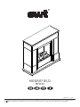
Dimplex MOOREFIELD MFD20 Operating instructions
- Category
- Cookers
- Type
- Operating instructions

The product complies with the European Safety Standards EN60335-2-30 and the European Standard Electromagnetic Compatibility (EMC)
EN55014, EN60555-2 and EN60555-3 These cover the essential requirements of EEC Directives 2006/95/EC and 2004/108/EC
08/51775/0 Issue 1
MOOREFIELD
MFD20
R
Page is loading ...
Page is loading ...
Page is loading ...
Page is loading ...
Page is loading ...
Page is loading ...
Page is loading ...
Page is loading ...
Page is loading ...
Page is loading ...
Page is loading ...

EWT Moorefi eld MFD20
Introduction
Please read this information guide carefully to be able to safely install, use and maintain your product.
Important Safety Advice
When using electrical appliances, basic precautions should always be followed to reduce the risk of fi re, electrical
shock and injury to persons, including the following:
1. OVERHEATING
WARNING: In order to avoid overheating, do not cover the heater. Do not place material or garments on the heater, or
obstruct the air circulation around the heater. The heater carries a DO NOT COVER warning.
2. DAMAGE.
If the appliance is damaged, check with the supplier before installation and operation.
If the supply cord is damaged it must be replaced by the manufacturer or service agent or a similarly qualifi ed person
in order to avoid a hazard.
3. LOCATION
Do not use outdoors.
Do not use in the immediate surroundings of a bath, shower or swimming pool.
Do not locate the heater immediately below a fi xed socket outlet or connection box.
Ensure that furniture, curtains or other combustible material are positioned no closer than 1 metre from the heater.
Although this heater conforms with safety standards, we do not recommend its use on deep pile carpets or on long
hair type of rugs.
4. PLUG POSITIONING
The appliance must be positioned so that the plug is accessible.
Keep the supply cord away from the front of the heater.
5. USE OF OTHER CONTROLS
Do not use this heater in series with a thermal control, a program controller, a timer or any other device that switches
on the heat automatically, since a fi re risk exists when the heater is accidentally covered or displaced.
6. UNPLUGGING
In the event of a fault unplug the device.
Unplug the device when not required for long periods.
7. OWNER/USER
This appliance is not intended for use by children or persons with reduced physical, sensory or mental capabilities,
or lack of experience and knowledge, unless they have been given supervision or instruction concerning use of the
appliance by a person responsible for their safety. Children should be supervised to ensure that they do not play with
the appliance.
8. ELECTRCITY
WARNING – THIS APPLIANCE MUST BE EARTHED.
This heater must be used on an AC ~ supply only and the voltage marked on the heater must correspond to the
supply voltage.
General Information
Only use decalcifi ed water in this appliance.
This model is designed to be free standing and is normally positioned near a wall.
Always ensure that the appliance is sitting on a level surface.
Although this heater complies with safety standards, we do not recommend its use on deep pile carpets or on long
hair type of rugs.
Please note: Used in an environment where background noise is very low, it may be possible to hear a sound which is
related to the operation of the fl ame effect. This is normal and should not be a cause for concern.
If this product experiences a power surge for whatever reason the product may cut-out. This is a normal safety feature
and the product will resume operation after 30 seconds.
Once installed, never move this appliance or lay on its back, without draining the water from sump and water tank.
If you intend not using the appliance for longer than 2 weeks, drain the water from sump and water tank and dry the
sump.
The water tank, sump, sump lid, tank cap and air fi lters must be cleaned once every two weeks, particularly in hard
water areas.
The appliance should never be operated if the lamps are not working.
The lamps should be regularly inspected as described under ‘Maintenance’ and ‘Changing lamps’.
Before switching on, please read the safety advice and operating instructions.
7

Installation Instructions
This section describes how to set up your fi re.
BEFORE YOU START
1. Ensure that all packing items are removed (read any warning labels carefully) and retain all packing for possible
future use e.g. in the event of moving house or returning the appliance to your supplier.
2. Before connecting the stove, check that the supply voltage is the same as that stated on the heater.
INSTALLATION
Hold the fi re by the sides of surround and gently manoeuvre into position.
Place the fi re against a wall and connect to your electricity supply.
Connect the power cable to the appropriate power connector at the back of the fi re.
Plug the power cable into a 16amp/230volt outlet. Ensure that the supply cable exits at the back of the fi re, at the right
or left hand corner to suit your supply socket location and is not trapped under the fi re such that it might cause it to be
damaged.
Do not yet switch the appliance on.
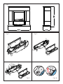
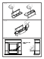
Connecting the Transducer Unit + Lamps
1. Release the two red tabs by turning them by 90 degrees (Fig 2)
2. Lift out the Sump Nozzle (Fig 3)
3. Insert lamps into lamp holders (Fig 4), carefully locating the pins into the holes (Fig 4a)
4. Push lamps fi rmly into place
5. Place the Transducer Unit into the sump and join the cable to the connector on the sump (Fig 5)
6. To ensure that the Transducer Unit is correctly placed in the sump, the tab on the Transducer Unit should be lined
up with the moulded recess in the sump (Fig 5a).
7. Ensure that the cable is not placed above the disc on the Transducer Unit (Fig 5b). To prevent the cable becoming
pinched between the nozzle and the sump, place the cable in the slot in the wall of the sump.
8. Replace the Sump Nozzle and secure it by turning the two red tabs by 90 degrees (Fig 6)
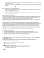
Filling the Water Tank
9. Place Water Tank in sink and remove cap (turn anti-clockwise to open) (Fig 7)
10. Fill Water Tank with decalcifi ed tap water only. This is necessary to prolong the life of the fl ame and smoke
producing unit. The water should be fi ltered through a conventional domestic water fi lter unit and the fi lter should
be replaced regularly.
11. Screw the cap back on – do not overtighten.
12. Place the Water Tank in the Sump, with the tank cap facing down and the fl at side of the tank facing outward (Fig 8)
Assembling the fi re
13. Place the Fuelbed on top of the Water Tank and Mist Nozzle (Fig 9)
Operating the Fire
This section describes how to activate your fi re using either the manual controls or remote control.
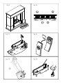
MANUAL CONTROLS
The manual controls are located beneath the hinged fl ap. (Fig.10 for Manual Control lay out)
Switch ‘A’:- Controls the electricity supply to the Fire.
Note: This switch must be in the ‘ON’ ( I ) position for the Fire to operate either with or without heat.
Switch ‘B’:- Press once to turn on the fl ame effect. This will be indicated by an audible beep. Although the main
lights operate immediately it will take a further 30 seconds before the fl ame effect starts.
Press
again to give fl ame effect and half heat. This will be indicated by two beeps.
Press
again to give fl ame effect and full heat. This will be indicated by three beeps.
Press again to return to fl ame effect only. This will be indicated by one beep.
Press to put fi re in to standby mode. This will be indicated by one beep.
Control Knob ‘C’:- Controls the Thermostat setting.
Turning the control knob to the left will decrease the temperature setting, turning the control knob
to the right will increase the temperature setting.
8

Control Knob ‘D’:- Controls the intensity of the fl ame effect.
Turning the control knob to the left increases the fl ame effect, turning the control knob to the right will
decrease the fl ame effect.
SETTING THE THERMOSTAT
Ensure the fi re is plugged in and switch it on to the full heat setting. Turn the Control Knob ‘C’ fully to the right (max
temperature setting) to warm the room rapidly. When the room temperature has reached the desired level, turn
the thermostat knob back slowly until you hear the thermostat just click off. The heater will then maintain the room
temperature at the chosen level.
Note: Should your heater fail to come on when the thermostat is at a low setting, this may be due to the room
temperature being higher then the thermostat setting
THERMAL SAFETY CUT-OUT
A thermal safety cut-out is incorporated in the fan heater to prevent damage due to overheating. This can happen if
the heat outlet was restricted in any way. If the cut-out operates, unplug the heater from the socket outlet and allow
approximately 10 minutes before reconnecting. Before switching the heater back on remove any obstruction that may
be restricting the heat outlet, then continue normal operation.
Caution: In order to avoid a hazard due to inadvertent resetting of the thermal cutout, this appliance must not be
supplied through an external switching device, such as a timer, or connected to a switch that is regularly switched on
and off by the utility.
GETTING THE DESIRED FLAME EFFECT
1. The fl ame control knob ‘D’ (Fig.10) may be turned up or down to give a more realistic effect.
2. Generally the fl ames appear more realistic when the fl ame control is turned down.
3. Give the fl ame generator time to react to changes you may make.
4. The fi re will use less water if the fl ame effect is set to a lower level.
5. Do not tilt or move the fi re while there is water in the tank or sump.
6. Make sure that the fi re is on a level fl oor.
REMOTE CONTROL OPERATION
On the control panel, Switch A (Fig.10) must be in the ‘ON’ ( I ) position in order for the remote control to operate.
There are 3 buttons on the remote control. (Fig.12) To operate correctly the remote must be pointed towards the front
of the grate. (Fig 17). The remote control functions are as follows:
Press once to turn on Flame effect only.
This will be indicated by one beep.
Press once to turn on Half Heat and Flame Effect.
This will be indicated by two beeps.
Press again to turn on Full Heat and Flame Effect.
This will be indicated by three beeps.
Standby
This will be indicated by one beep.
Maintenance
GENERAL TIPS
Only use decalcifi ed tap water in this appliance.
Always ensure that the appliance is sitting on a level surface.
If you intend not using the appliance for longer than 2 weeks, remove and empty the sump and water tank.
Once installed, never move this appliance or lay on its back, without draining the water from sump and water tank.
The appliance should never be operated if the lamps are not working.
The lamps should be regularly inspected as described under ‘Changing lamps’.
FILLING THE WATER TANK
When the water tank is empty, the fl ame and smoke effect shuts off and you will hear 2 audible beeps, follow these
steps.
1. Press Switch ‘A’ to (0) (Fig.10)
2. Gently lift out the fuelbed and carefully set aside.
3. Remove the water tank by lifting upwards and outwards.
4. Place the water tank in sink and remove cap, Anti-clockwise to open. (Fig 7)
5. Fill tank with decalcifi ed tap water only. This is necessary to prolong the life of the fl ame and smoke producing
unit.
The water should be fi ltered through a conventional domestic water fi lter unit and the fi lter should be replaced
9

regularly.
6. Screw the cap back on, do not over tighten.
7. Return the tank to the sump, with the tank cap facing down and the fl at side of the tank facing outward. (Fig 8)
8. Gently place the fuelbed back into position. (Fig 9)
9. Press Switch ‘A’ to ‘ON’ (I) position (Fig.10)
CHANGING LAMPS
If the fl ame and smoke effect appears grey or colourless it may be that one or more lamps have failed.
You can check for lamp failure as follows.
1. Leaving the fl ame effect on, lift out the fuelbed and water tank.
2. It should be possible to view the lamps with the nozzle in place and observe which one needs to be changed.
3. Put Switch ‘A’ in the ‘OFF’ position, and unplug the fi re from the mains.
4. Leave the appliance for 20 minutes to allow the lamps to cool down before removing them.
5. Remove the sump as described in the Cleaning Section.
6. Remove the defective lamp, by gently lifting vertically and disengaging the pins from the lamp holder, (Fig.4 and
4a).
Replace with a OPTIMYST, 12V, 50W, Gu5.3 base, 8º beam angle, coloured lamp. (To purchase replacement lamps
go to the section ‘After Sales Service’, details of how to purchace the lamps are contained therein.)
7. Carefully insert the two pins of the new lamp into the two holes in the lamp holder. Push fi rmly in place. (Fig.4 and
4a).
8. Replace the sump, nozzle, water tank and fuelbed.
CLEANING
Warning – Always press Switch ‘A’ to the ‘OFF’ (0) position (Fig.10) and disconnect from the power supply before
cleaning the fi re.
We recommend cleaning the following components once every 2 weeks, particularly in hard water areas:-
Water Tank, Sump, Nozzle, Tank cap and seal, Air fi lter.
For general cleaning use a soft clean duster – never use abrasive cleaners.
To remove any accumulation of dust or fl uff the soft brush attachment of a vacuum cleaner should occasionally be
used to clean the outlet grille of the fan heater.
Water tank
1. Remove water tank, as described earlier, put into sink and empty water.
2. Using the supplied brush gently rub the inside surfaces of the cap paying particular attention to the rubber ring in
the outer groove and the centre rubber seal.
3. Put a small quantity of washing up liquid into the tank, refi t the cap and shake well, rinse out until all traces of
washing up liquid are gone.
4. Refi ll with decalcifi ed tap water only, replace the cap, do not overtighten.
Sump
1. Press Switch ‘A’ to the ‘OFF’ (0) position
2. Gently lift out the fuelbed and place carefully on the ground.
3. Remove the water tank by lifting upwards.
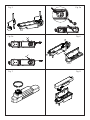
4. Disconnect the electrical connector, located on the right side of the sump. (Fig.5) .
5. Release the right sump locking tabs by turning 90º. This allows the sump to be lifted completely from its location.
(Fig. 11)
6. Gently lift up the sump, taking care to keep level so as not to spill any water. Sit the assembly in the sink.
7. Release the left sump locking tabs by turning 90º, then lift off the Nozzle. (Fig.3)
8. Lift out the transducer and carefully tilt, as shown, so that the liquid drains out of the sump. (Fig.13)
9. Put a small amount of washing up liquid into the sump, and using the supplied brush, gently clean all surfaces in the
sump and gently clean the transducer including the metal discs located in the top grooved surface. (Fig.14)
10. When cleaned, thoroughly rinse the sump with clean water to remove all traces of washing up liquid.
11. Clean the Nozzle with the brush and fl ush out thoroughly with water. (Fig.15)
12. Reverse the above steps to reassemble.
Air fi lter
1. Gently lift out the fuelbed and place carefully on the ground.
2. Gently slide the air fi lter upwards out of its plastic holder. (Fig.16)
3. Gently rinse with water in the sink and dry with fabric towel before returning.
4. Replace the fi lter making sure that the coarse black fi lter is facing the front of the fi re.
5. Replace the fuelbed.
10

Additional Information
AFTER SALES SERVICE
Your product is guaranteed for two years from the date of purchase. Within this period, we undertake to repair or
exchange this product free of charge (excluding lamps & subject to availability) provided it has been installed and
operated in accordance with these instructions. Your rights under this guarantee are additional to your statutory rights,
which in turn are not affected by this guarantee.
Should you require after sales information or assistance with this product please go to warrenty card at back of
the book where you can ring our help desk. Spare parts are also available. Please retain your receipt as proof of
purchase.
RECYCLING
For electrical products sold within the European Community - At the end of the electrical products useful life
it not be disposed of with household waste. Please recycle where facilities exist. Check with your Local
Authority or retailer for recycling advice in your country.
PATENT / PATENT APPLICATION
Products within the Optimyst range are protected by one or more of the following patents and patent applications:
Great Britain GB 2402206, GB 2460259, GB 2460453 , GB 2418014, GB 2465738, GB 2449925, GB 2465537 , GB
2455277 , GB1020534.2, GB1020537.5, GB1110987.3
United States US 7967690, US 2010299980, US 2011062250, US 2008028648, US 13/167,042
Russia RU2008140317
European EP 2029941, EP 2201301, EP 2315976, EP 1787063, EP07723217.1 , EP11170434.2, EP 11170435.9
China CN 101883953, CN 200980128666.2, CN 101057105, CN 101438104
Australia AU 2009248743, AU 2007224634
Canada CA 2725214, CA 2579444, CA 2645939
International Patent Application WO 2006027272
South Africa ZA 200808702
Mexico MX 2008011712
Korea KR 20080113235
Japan JP 2009529649
Brazil BR P10708894-9
India IN 4122/KOLNP/2008
New Zealand NZ 571900
11

Symptom Cause Corrective Action
The fl ame effect will
not start.
Mains plug is not plugged in.
Low water level.
Low voltage connector not connected
properly. (Fig.5)
The Transducer Unit is not sitting correctly in
the sump
When distilled water is being used, the
transducer may not start.
Check plug is connected to wall socket
correctly.
Check that the water tank is full and there is
water in the sump.
Check that the connector is inserted
correctly. (Fig.5)
Ensure the Transducer in sitting down into
the moulded recess in the sump.
Please use tapped, decalcifi ed water at the
beginning and try distilled water later.
The fl ame effect is too
low.
Flame effect control knob is set too low.
(Fig.10)
The Metal Disc in the transducer might be
dirty (Fig.14)
The wire from the Transducer Unit is sitting
over the metal disc
Low mist at start up.
Increase level of fl ame by turning Control
knob ‘D’ to the left slowly. (Fig.10)
Clean the Metal Disc with soft brush
supplied. (Fig.14) See ‘Maintenance.’ for a
step by step procedure.
Direct the wire to the back of the sump and
make sure it sits into the side slot exiting the
sump.
Before fi rst operation: please allow the fi re
place to warm up to room temperature.
Unpleasant smell
when unit is used.
Dirty or stale water.
Using unfi ltered tap water.
Clean the unit as described under
maintenance.
Use only fi ltered tap water.
The fl ame effect has
too much smoke.
Flame effect setting is too high. Turn the fl ame effect Control knob ‘D’ to
the right, about ¼ a turn, at a time. Give the
fl ame generator some time to adjust to the
new setting. (Fig.10)
Main lamps are not
working and there are
no fl ames or smoke.
There is no water in the water tank Follow instructions under
Maintenance, ‘Filling the water tank’.
Check the plug is connected to the wall
socket correctly and that Switch ‘A’ Fig. 10 is
in the ‘ON’ ( I ) position.
Troubleshooting
12
Page is loading ...
Page is loading ...
Page is loading ...
Page is loading ...
Page is loading ...
Page is loading ...
Page is loading ...
Page is loading ...
Page is loading ...
Page is loading ...
Page is loading ...
Page is loading ...
Page is loading ...

2. Garantiezeitraum 3. Modell(e)
4. Kaufdatum
5. Stempel & Unterschrift des
Einzelhändlers
7.
Kontakt-Tel.-Nr. & - Anschrift
1. Garantiekarte
2
GR
1. Κάρτα εγγύησης
εγγύησης (έτη)
6. Σφάλµα/Ελάττωµα
KZ
SK
1. Zárucný list
2. Zárucné obdobie (v rokoch)
3. Model(y)
4. Dátum kúpy
5. Pecat & Podpis obchodníka
6. Porucha/závada
7. Kontaktujte císlo & adresu
LT
1. Garantijos kortele
2. Garantijos laikotarpis (metais)
3. Modelis (modeliai)
4. Pirkimo data
5. Prekybininko antspaudas ir
parašas
6. Gedimas / defektas
7. Numeris ir adresas kontaktams
EE
1. Garantiikaart
2. Garantiiaeg (aastates)
3. Mudel(id)
4. Ostukuupäev
5. Kaupluse tempel & allkiri
6. Viga/defekt
7. Kontaktnumber & aadress
HU
1. Garancialevél
2. Garancia idotartama (években)
3. Modell(ek)
4. Vásárlás idopontja
5. Eladó bélyegzoje és aláírása
6. Hiba/Hiány megnevezése
7. Értesítési telefonszám és cím
HR
1. Jamstvena kartica
2. Jamstveni period (u godinama)
3. Model(i)
4. Datum kupnje
5. Pecat i potpis dobavljaca
6. Kvar/defekt
7. Broj i adresa za kontakt
FI
1. Takuukortti
2. Takuuaika (vuosina)
3. Malli(t)
4. Ostopäivämäärä
5. Myyntiliikkeen leima ja
allekirjoitu
s
6. Vika/vaurio
7. Yhteysnumero ja osoite
PL
1. Karta gwarancyjna
2. Okres gwarancji (w latach)
3. Model(e)
4. Data zakupu
5. Pieczec i podpis sprzedawcy
6. Usterka
7. Telefon i adres kontaktowy
CZ
1. Záruční list
2. Záruční doba (roky)
3. Model(y)
4. Datum zakoupení
5. Razítko a podpis prodejce
6. Porucha/chyba
7. Kontaktní číslo a adresa
LV
1. Garantijas talons
2. Garantijas periods (gadi)
3. Modelis(li)
4. Legades datums
5. Mazumtirgotaja zimogs un
parakst
s
6. Bojajums/defekts
7. Kontakttalrunis un adrese
SI
1. Garancijski list
2. Obdobje veljavnosti
garancije (v letih)
3. Model(i)
4. Datum nakupa
5. Žig in podpis prodajalca
6. Pomanjkljivost/okvara
7. Kontaktna številka in naslov
PT
1. Cartão de Garantia
2. Período de Garantia (em anos)
3. Modelo(s)
4. Data de Compra
5. Carimbo e Assinatura do
retalhista
6. Falha/Defeito
7. Número de Contacto e Morada
NL
1. Garantiebewijs
2. Garantieperiode (in jaren)
3. Model(len)
4. Aankoopdatum
5. Stempel & handtekening
winkelie
r
6. Storingen & gebreken
7. Telefoonnummer & adres
DK
1. Garantikort
2. Garantiperiode (i år)
3. Model(ler)
4. Købsdato
5. Detailhandlers stempel &
underskrift
6. Fejl/defekt
7. Kontaktnummer & -adresse
SE
1. Garantikort
2. Garantitid (i år)
3. Modell(er)
4. Inköpsdag
5. Återförsäljarens stämpel och
underskrift
6. Fel
7. Telefonnummer och adress för
konta
kt
NO
1. Garantikort
2. Garantiperiode (i år)
3. Modell(er)
4. Kjøpsdato
5. Selgers stempel og signatur
6. Feil/defekt
7. Kontaktnummer og adresse
DE
1. Garantiekarte
2. Garantiezeitraum (in Jahre)
3. Modell(e)
4. Kaufdatum
5. Stempel & Unterschrift
des Einzelhändlers
6. Fehler/Defekt
7. Kontakt-Tel.-Nr. & - Anschrift
UK
1. Warranty Card
2. Guarantee Period (in Years)
3. Model(s)
4. Date of Purchase
5. Stamp & Signature of retailer
6. Fault/Defect
7. Contact Number & Address
FR
1. Bon de garantie
2. Période de garantie (en années)
3. Modèle(s)
4. Date d’achat
5. Cachet et signature du vendeur
6. Anomalie/Défaut
7. Nom et adresse du contact
IT
1. Scheda di garanzia
2. Periodo di garanzia (in anni)
3. Modello(i)
4. Data di acquisto
5. Timbro e firma del rivenditore
6. Guasto/difetto
7. Indirizzo e numero di contatto
ES
1. Tarjeta de garantía
2. Período de garantía (en años)
3. Modelo(s)
4. Fecha de adquisición
5. Sello y firma del distribuidor
6. Avería/Defecto
7. Número y dirección de contacto
6. Fehler/Defekt
AT
Firma Schurz
Merangasse
17
A-8010
Graz
+43
(316) 32 30 41
Fax
: +43 (316) 38 29 63
office@schurz.bi
z
R
DE
Glen Dimplex Deutschland Gmbh
ew
t-Kundendienst
+49 1805 / 398 346
Fax
. +49 1805 / 355 467
(14Ct./Min.
aus dem dt. Festnetz,
max.42Ct./Min. aus
dem
Mobilfunk
)
service@glendimplex.d
e
NO
Dimplex AS,
NO - 7493 Trondheim,
Norway.
+(47)
73 95 94 00
Fax
: +(47) 73 95 90 90
CH
BLUEPOINT Service Sagl,
Via
Cantonale 14,
C.
P. 46,
CH
- 6917 Barbengo
+(41)
091 980 49 72
Fax
: +(41) 091 605 37 55
eMail:
info@bluepoint-service.ch
www.bluepoint-service.c
h
FR
Glen Dimplex France
ZI
Petite Montagne Sud
12
rue des Cévennes
91017
EVRY - LISSES
www
.glendimplex-france.fr
NL
Glen Dimplex Benelux B.V. – Netherlands
Saturnus 8,
8448 CC Heerenveen
,
Nede
rland.
E-mail: info@glendimplex.nl
www.glendimplex.n
l
BE
Glen Dimplex Benelux B.V. – Belgium
Burg. Maenhautstraat 64,
B-
9820 Merelbeke,
België/ Belgique
E-mail
: info@glendimplex.be
www.glendimplex.b
e
LT
UAB “Senuku prekybos centras”
Pramones pr. 6,
LT-51500,
Kaunas
.
(8~800)
111 19
(8~37)
21 21 46
PL
Glen Dimplex Polska Sp. z o.o.
ul. Strzeszynska 33,
60-479 Poznan
,
Poland
061 8425 805
Fax
: 061 8425 806
eMail
: office@glendimplex.pl
Bratsbergvegen 5,
eMail: email@glendimplex.no
-
 1
1
-
 2
2
-
 3
3
-
 4
4
-
 5
5
-
 6
6
-
 7
7
-
 8
8
-
 9
9
-
 10
10
-
 11
11
-
 12
12
-
 13
13
-
 14
14
-
 15
15
-
 16
16
-
 17
17
-
 18
18
-
 19
19
-
 20
20
-
 21
21
-
 22
22
-
 23
23
-
 24
24
-
 25
25
-
 26
26
-
 27
27
-
 28
28
-
 29
29
-
 30
30
-
 31
31
-
 32
32


Dimplex MOOREFIELD MFD20 Operating instructions
- Category
- Cookers
- Type
- Operating instructions
Ask a question and I''ll find the answer in the document
Finding information in a document is now easier with AI
in other languages
Related papers
-
Dimplex RTOPCS20 User manual
-
-
-
Dimplex WLL20-AU User manual
-
-
Dimplex CAS500 Owner's manual
-
-
-
Faber Presada PRS20 User manual
-
Other documents
-
Bionaire BEF5000 Owner's manual
-
 Ruby TFTT5000 Installation And Operating Instructions Manual
-
Stadler Form MAX Operating instructions
-
Silvercrest SEK 2000 B2 Operation And Safety Instructions
-
 Planika Misty Owner's manual
-
 Olimpia Splendid Astomi 200 User manual
-
Francis Francis X1 Trio User manual
-
Burley 537E-R Operating Instructions Manual
-
Gastroback 42606 Operating instructions
-
Diamond OASI 8M BM/LUX User manual


