Page is loading ...

EurotestDL
MI 3002
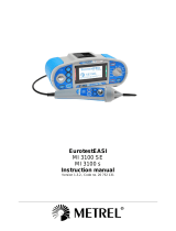
EurotestEASI
MI 3100
Short instructions
Version 2.3 UK, Code No. 20 750 114

2
Distributor:
Manufacturer:
METREL d.d.
Ljubljanska cesta 77
1354 Horjul
Slovenia
web site: http://www.metrel.si
e-mail: [email protected]
Mark on your equipment certifies that this equipment meets the requirements of the EU
(European Union) concerning safety and interference causing equipment regulations
© 2009 METREL
No part of this publication may be reproduced or utilized in any form or by any means
without permission in writing from METREL.

Safety and operational considerations
3
1 Safety and operational considerations
1.1 Warnings
• This document is a supplement to the Instruction manual!
• Before using EurotestEASI instrument read the Instruction manual carefully,
otherwise use of the instrument may be dangerous for the operator, for the
instrument or for equipment under test!
• symbol on the instrument means »Read the Instruction manual with special
care«. The symbol requires an action!
• If the test equipment is used in a manner not specified in Instruction manual
the protection provided by the equipment may be impaired!
• Do not use the instrument and accessories if any damage is noticed!
• In case a fuse has blown follow the instructions in Instruction manual to
replace it!
• Consider all generally known precautions in order to avoid risk of electric
shock while dealing with hazardous voltages!
• Do not use the instrument in supply systems with voltages higher than 550 V!
• Service intervention or adjustment procedure is allowed to be carried out only
by a competent authorized person!
• Use only standard or optional test accessories supplied by your distributor!
• Consider that older and some of new optional test accessories compatible with
this instrument meet only overvoltage category CAT III / 300 V! It means that
maximal allowed voltage between test terminals and ground is 300 V!
• Instrument contains rechargeable Ni-Cd or Ni-MH battery cells. The cells
should only be replaced with the same type as defined on the battery
placement label or in Instruction manual. Do not use standard alkaline battery
cells while power supply adapter is connected, otherwise they may explode!
• Hazardous voltages exist inside the instrument. Disconnect all test leads,
remove the power supply cable and switch off the instrument before removing
battery compartment cover.
• All normal safety precautions have to be taken in order to avoid risk of electric
shock when working on electrical installations!

Safety and operational considerations
4
1.2 Battery handling
• When battery cells have to be replaced or before opening battery/fuse
compartment cover, disconnect any measuring accessory connected to the
instrument and power off the instrument, hazardous voltage inside!
• Insert cells correctly, otherwise the instrument will not operate and the battery could
be discharged.
• If the instrument is not used for a long period of time remove the battery from its
compartment.
• Alkaline or rechargeable Ni-Cd or Ni-MH battery cells (size AA) can be used. The
operating hours are given for cells with a nominal capacity of 2100 mAh.
• Do not recharge alkaline battery cells!
The battery is charged whenever the power supply adapter is connected to the instrument.
In-built protection circuits control the charging procedure and assure maximal battery
lifetime. Power supply socket polarity is shown in the figure below.
+
-
Power supply socket polarity
Note:
• Use only power supply adapter delivered from manufacturer or distributor of the test
equipment to avoid possible fire or electric shock!
2 Function selector switch and instrument display
1
1
2
3
4
Legend:
1..... Main function name.
2..... Function or sub-function name.
3..... Measuring parameters and limit values.
4..... Result field.
In this field the main and sub-results together with the PASS/FAIL/ABORT status are
displayed.
5..... Online voltage and output monitor.
6..... Message field.
In this field battery status and warnings/messages related to the actual measurement
are displayed.

Measurements Continuity
5
3 Measurements
3.1 Continuity
1
Set function
2
Set sub-function
3
Set parameters and limits
LowΩ
Continuity
High limit resistance
[∗Ω sets limit off, 0.1 Ω ÷
20.0 Ω]
4
Connection diagram
LowΩ
Continuity
PCC1
PCC2
PCC3
N/L2
PE/L3
L/L1
MPEC
MPEC....Main Potential Equilizing Collector
PCC....Protection Conductor Collector
prolongation lead
PCC1
PCC2
PCC3
MPEC
MPEC....Main Potential Equilizing Collector
PCC....Protection Conductor Collector
prolongation lead
Ry
Sz
T
x
N
/
L
2
P
E
/
L
3
L
/
L
1
R
y
S
z
T
x
5
Press the
TEST
key.
Press the
TEST
key to start. Press the
TEST
key
again to stop measurement.
6
View results
Displayed results:
R: Main LowΩ resistance result
R+: LowΩ resistance sub-result with positive voltage
at L terminal
R-: LowΩ resistance sub-result with positive voltage
at N terminal
Displayed results:
R: Main continuity resistance result

Measurements Insulation resistance
6
3.2 Insulation resistance
1
Set function
2
Set parameters and limits
Nominal test voltage
[100 V
DC
÷ 1000 V
DC
]
Low limit resistance value
[∗Ω sets limit off, 0.01 MΩ ÷ 200 MΩ]
3
Connection diagram
L1
L2
L3
N
PE
switched off
mains voltage
closed
switches
disconnec-
ted loads
N/L2
L
/
L
1
PE/L3
4
Press and hold the
TEST
key until result is stabilised.
5
View results
Displayed results:
R: Insulation resistance
Um: Instrument test voltage

Measurements Line impedance and PSC
7
3.3 Line impedance (phase-neutral, phase-phase)
1
Set function
2
Set parameters and limits
Fuse type [∗F sets limit off, BS88, BS3036,
BS1361, BS1362, B, C, D]
Fuse current rating [6 A ÷ 200 A]
Fuse tripping time [0.4 s, 5 s]
3
Connection diagram
L1
L2
L3
N
PE
R
E
Ro
LPEN
L
/
L
1
N
/
L
2
P
E
/
L
3
N/L2
L
/
L
1
PE/L3
4
Press the
TEST
key.
5
View results
Displayed results:
Z: Line impedance
I
SC
: Prospective short-circuit current
Lim: High limit line impedance value (if applicable)

Measurements Fault loop impedance and PFC
8
3.4 Fault loop impedance
1
Set function
2
Set sub-function
3
Set parameters and limits
Zs
Zs (rcd)
Fuse type [∗F sets limit off,
BS88, BS3036, BS1361,
BS1362, B, C, D]
Fuse current rating
[6 A ÷ 200 A]
Fuse tripping time
[0.4 s, 5 s]
4
Connection diagram
Zs
L1
L2
L3
N
PE
R
E
Ro
LPEN
L
/
L
1
N
/
L
2
P
E
/
L
3
Zs (rcd)
L1
L2
L3
N
PE
R
E
Ro
LPEN
L
/
L
1
N
/
L
2
P
E
/
L
3
5
Press the
TEST
key.
6
View results
Displayed results:
Z: Fault loop impedance
I
SC
: Prospective fault current
Lim: High limit fault loop impedance value (if applicable)

Measurements RCD testing
9
3.5 RCD testing
1
Set function
2
Set sub-function
3
Set parameters and limits
Contact voltage
Tripping time
Tripping current
RCD autotest
Limit contact voltage [25V,
50V]
Nominal differential RCD
tripping current
[10 mA ÷ 1000 mA]
Multiplier of nominal
differential RCD tripping
current [×½, ×1, ×2, ×5]
Test current starting polarity
and RCD type [
G,
G, S, S, G,
G, S, S]
4
Connection diagram
L1
L2
L3
N
PE
R
E
Ro
LPEN
L
/
L
1
N
/
L
2
P
E
/
L
3
5
Press the
TEST
key.
6
View results
Displayed results:
U
C
: Contact voltage
R
L
: Fault loop resistance
Lim: High limit fault loop
resistance
Displayed results:
t: Tripping time
U
C
: Contact voltage
Displayed results:
I
Δ
: Tripping current
U
CI
: Contact voltage
tI: Tripping time
Displayed results:
U
C
: Contact voltage
t1-t6: Tripping times

Measurements Voltage and frequency
10
3.6 Voltage and frequency
1
Set function
2
Connection diagram
L1
L2
L3
N
PE
R
E
Ro
LPEN
L
/
L
1
N
/L
2
P
E
/
L
3
N/L2
L
/
L
1
PE/L3
3
View results
Displayed results:
Ul(1)-n(2): Voltage between phase and neutral conductors (or between phases L1 and L2)
Ul(1)-pe(3): Voltage between phase and protective conductors (or between phases L1 and L3)
Un(2)-pe(3): Voltage between neutral and protective conductors (or between phases L2 and L3)

Measurements Phase sequence
11
3.7 Phase sequence
1
Set function
2
Connection diagram
L3
L2
L1
N
PE
N
/
L
2
N
/
L
2
L
/
L
1
L
/
L
1
P
E
/
L
3
P
E
/
L
3
result 1.2.3
option A 1110
result 2.1.3
3
View results
Displayed result:
Ph: Phase sequence
1.2.3: Correct connection
2.3.1: Invalid connection
-.-.-: Irregular voltages

Maintenance
12
4 Maintenance
4.1 Replacing fuses
• F1
M 0.315 A / 250 V, 20×5 mm
This fuse protects internal circuitry of low-value resistance function if test probes are
connected to the mains supply voltage by mistake.
• F2, F3
F 4 A / 500 V, 32×6.3 mm
General input protection fuses of test terminals L/L1 and N/L2.
Warnings:
• Disconnect any measuring accessory and power off the instrument before
opening battery/fuse compartment cover, hazardous voltage inside!
• Replace blown fuse with original type only, otherwise the instrument may be
damaged and/or operator’s safety impaired!
5
6
4
1
2
3
F1
F3
F2
Fuse
Fuse
Fuse
SIZE AASIZE AA
SIZE AA
SIZE AASIZE AASIZE AA
S/N XXXXXXXX
Battery and fuse compartment
Legend:
1 Fuse F1
2 Fuse F2
3 Fuse F3
4 Serial number label
5 Battery cells (size AA)
6 Battery holder
/


