METREL EurotestAT MI 3101 Short Instructions

Category
Cable network testers
Type
Short Instructions

METREL EurotestAT MI 3101 is a versatile electrical safety analyzer designed to perform a wide range of tests on electrical installations, including insulation resistance, continuity, RCD tripping time, and loop impedance. It features a user-friendly interface, a large backlit display, and the ability to store and transfer test results. With its comprehensive testing capabilities, the EurotestAT MI 3101 is an essential tool for ensuring the safety and compliance of electrical systems.

METREL EurotestAT MI 3101 is a versatile electrical safety analyzer designed to perform a wide range of tests on electrical installations, including insulation resistance, continuity, RCD tripping time, and loop impedance. It features a user-friendly interface, a large backlit display, and the ability to store and transfer test results. With its comprehensive testing capabilities, the EurotestAT MI 3101 is an essential tool for ensuring the safety and compliance of electrical systems.

EurotestAT
MI 3101
Short instructions
Version 4.1, HW5, Code no. 20 751 321
Distributor:
Manufacturer:
METREL d.d.
Ljubljanska cesta 77
1354 Horjul
Slovenia
web site: http://www.metrel.si
Mark on your equipment certifies that this equipment meets the requirements of the EU
(European Union) concerning safety and interference causing equipment regulations
© 2006..2010 METREL
No part of this publication may be reproduced or utilized in any form or by any means
without permission in writing from METREL.
2
MI 3101 EurotestAT Safety and operational considerations
3
1. Safety and operational considerations
1.1. Warnings
This document cannot be a substitute for the Instruction manual!
Before using EurotestAT instrument read the Instruction manual carefully,
otherwise use of the instrument may be dangerous for the operator, for
the instrument or for equipment under test!
Symbol on the instrument means »Read the Instruction manual with
special care«. The symbol requires an action!
If the test equipment is used in a manner not specified in Instruction
manual the protection provided by the equipment may be impaired!
Do not use the instrument and accessories if any damage is noticed!
In case a fuse has blown follow the instructions in Instruction manual to
replace it!
Consider all generally known precautions in order to avoid risk of electric
shock while dealing with hazardous voltages!
Do not use the instrument in supply systems with voltages higher than
550 V!
Service intervention or adjustment and calibration procedure is allowed to
be carried out only by a competent authorized person!
Use only standard or optional test accessories supplied by your
distributor!
Consider that older and some of new optional test accessories compatible
with this instrument meet over voltage category CAT III / 300 V! It means
that maximum allowed voltage between test terminals and ground is 300
V!
Instrument contains rechargeable NiCd or NiMh batteries. The batteries
should only be replaced with the same type as defined on the battery
placement label or in Instruction manual. Do not use standard batteries
while power supply adapter is connected, otherwise they may explode!
Hazardous voltages exist inside the instrument. Disconnect all test leads,
remove the power supply cable and switch off the instrument before
removing battery compartment cover.
MI 3101 EurotestAT Safety and operational considerations
4
1.2. Batteries
When battery cells have to be replaced or before opening battery/fuse
compartment cover, disconnect any measuring accessory connected to the
instrument and power off the instrument, hazardous voltage inside!
Insert cells correctly, otherwise the instrument will not operate and the batteries
could be discharged.
If the instrument is not used for a long period of time remove all batteries from
the battery compartment.
Alkaline or rechargeable Ni-Cd or Ni-MH batteries (size AA) can be used. The
operating hours are given for cells with normal capacity of 2100 mAh.
Do not recharge alkaline batteries!
The batteries are charged whenever the power supply adapter is connected to the
instrument. In-built protection circuits control the charging procedure and assure
maximal battery lifetime. Power supply socket polarity is shown in figure below.
+
-
Power supply socket polarity
Note:
Use only power supply adapter delivered from manufacturer or distributor of
the test equipment to avoid possible fire or electric shock!
MI 3101 EurotestAT Safety and operational considerations
1.3. Communication
There are two communication interfaces available on the instrument: USB and RS 232.
How to select interface port on the instrument:
Select the
menu and then the option.
With the keys / select communication port ( or ).
Press the TEST key to confirm selected port.
How to transfer stored data:
Select appropriate communication interface (USB / RS 232).
Power on the PC and the instrument.
Run the program Eurolink.
The PC and the instrument automatically recognize each other.
Use the program for: downloading data, clearing storage, modifying user
data, preparing reports and exporting for spreadsheet.
Note:
Only one interface port of the instrument can be active at the same time.
USB drivers should be installed on PC before using the USB interface. Refer
to USB installation instructions available on installation CD.
Communication transfer speed:
RS 232 ................ 115200 baud
USB..................... 256000 baud
5
MI 3101 EurotestAT Instrument front panel
6
2. Instrument front panel
Legend:
1 ..... Switches the instrument power on or off.
2 ..... Accesses help menus.
3 ..... Adds new memory location/ Confirmation of name entered in edit mode.
4 ..... Enters memory editing mode/ Deletes character on the left in edit mode.
5 ..... Memory handling.
6 ..... Exits selected and displayed option.
7 ..... Jumps between display windows (TAB).
8 ..... Cursor keypad with TEST key.
9 ..... Changes backlight level and contrast.
10 ... 320 x 240 dots matrix display with backlight.
MI 3101 EurotestAT Auto sequence
7
3. Auto sequence
1
Set function
2
Set parameters and limits
Select Auto sequence in Main menu.
Use cursors / to select appropriate
test sequence.
/ ... Select auto sequence step or parameter.
/ ... Select test function or parameter value.
TAB ..... Enters test function parameters setup menu.
F1......... Name / description or pause / comment menus.
3
Building auto sequence procedure
Select auto sequence in the main menu.
Press the TEST key.
Select auto sequence number ( / ).
Edit name and description if necessary (F1).
Repeat until finished (maximum 6 steps):
Select auto sequence step ( / ).
Select auto sequence function ( / ).
Select auto sequence test parameters of the function (TAB).
Set / reset pause flag
II
and select or enter comment if necessary (F1).
Name (or rename) the auto sequence (F1).
Save prepared auto sequence (F2).
4
Running auto sequence
Select auto sequence in the main menu.
Select correct auto sequence ( / ).
Connect the instrument to tested object.
Press TEST key.
The sequence will pause at the functions marked with pause flag
II
.
Press the TAB key to toggle between comments menu and auto sequence
main menu.
Press the TEST key to continue with the auto sequence.
Press the F1 key to skip the target function or the ESC key to skip the
remaining functions and finish the auto sequence.
The sequence will stop when invalid condition of test terminals is detected. It will:
Continue after correct condition is restored.
Skip the target function by pressing the F1 key or the remaining functions and
finish the auto sequence by pressing the ESC key.
Results of a finished auto sequence can be viewed and stored.
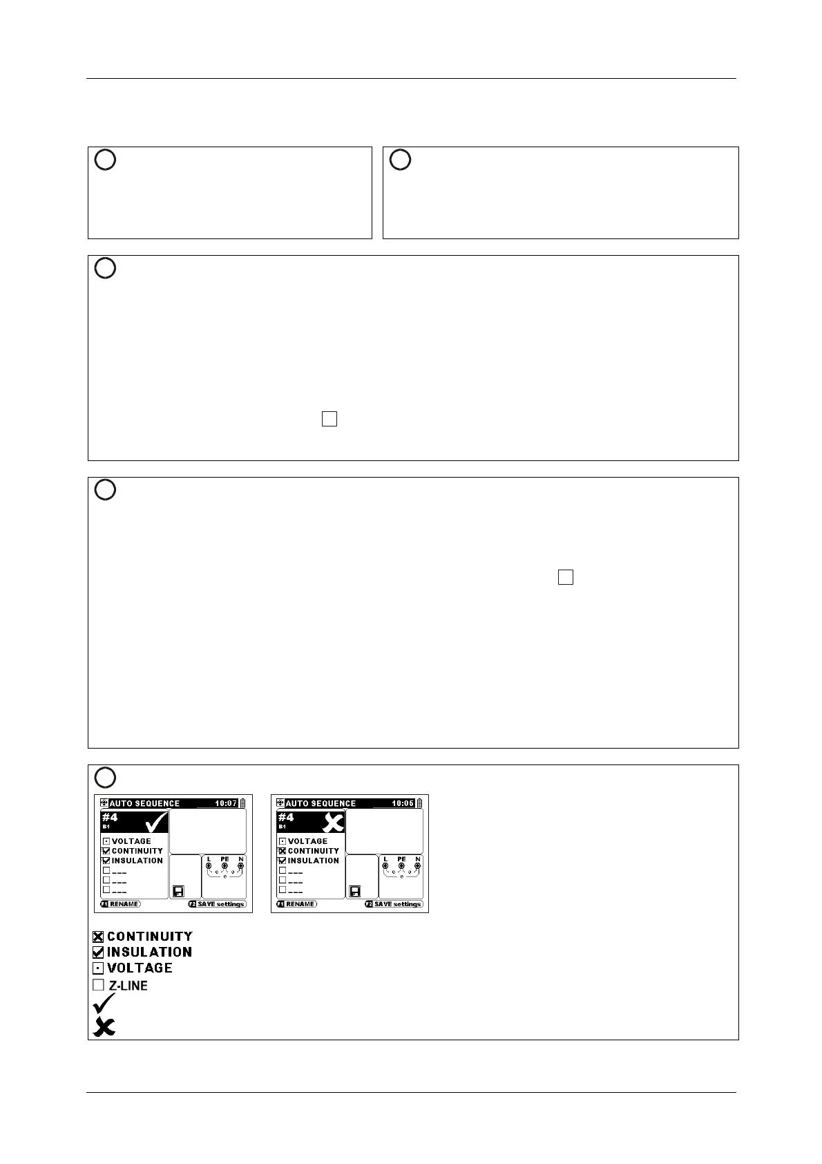
5
View results Particular test results
The key into sequence field.
Press TEST key to display result of
selected function.
Press TEST or ESC key.
The key (or ) for next function.
Repeat this part for all results.
The key or the ESC key to exit view.
Displayed results:
............... Measurement is finished and has failed.
............... Measurement is finished and has passed.
...................... Measurement is finished. No comparison limit was applied.
.............................. Measurement is not performed yet (during test) or was skipped.
........................................ Overall PASS result is reported if all performed tests passed.
........................................ Overall FAIL result is reported if one or more performed tests failed.
MI 3101 EurotestAT Measurements
8
4. Measurements
4.1. Inspections
1
Set function
2
Set parameters
Select Single test in Main menu.
Use cursors / to find and choose the VISUAL
function.
Use cursors / to select appropriate item.
Item......Inspection schedules.
3
Visual inspection procedure
Select Schedule type.
Press TEST key to start inspection.
Browse through items line by line and apply appropriate flags.
Press TEST or ESC key to stop inspection.
Store the result (optional).
4
View results
Markings:
................................. Inspection was not performed
................................. Inspection passed.
................................. Inspection failed.
................................. Inspection was performed in limited extent.
................................. Inspection was not applicable.
MI 3101 EurotestAT Measurements
9
4.2. Insulation resistance
1
Set function
2
Set parameters and limits
Select Single test in Main menu.
Use cursors / to find and choose the INSULATION
function.
TEST
.....Test configuration.
U
iso
.........Test voltage.
Limit
......Minimum insulation resistance.
3
Test circuits for insulation resistance
L1
L2
L3
N
PE
mains voltage
switched off
closed
switches
loads disconnected
N/L2
L
/
L
1
PE/L3
Connection of universal test cable for general insulation resistance measurement (TEST: L-PE)
L1
L2
L3
N
PE
LPEN
L
/
L
1
N
/
L
2
P
E
/
L
3
mains voltage
switched off
loads disconnected
L1L2L3
L
/
L
1
N
/
L
2
P
E
/
L
3
loads disconnected
Application of plug cable or universal test cable for insulation resistance measurement
(TESTS: ‘L-PE,N-PE’, ‘L-N,L-PE’, ALL; L1-L2, L1-L3, L2-L3, All 3ph)
4
Insulation resistance measuring procedure
Disconnect tested installation from mains supply (and discharge tested insulation).
Connect test cable to the instrument and tested item.
Press the TEST key for measurement (keep pressing for continuous measurement).
After the measurement is finished store the result (optional).
5
View results
Displayed results:
Rln
....... Insulation resistance between L (+) and N (-).
Rlpe
..... Insulation resistance between L (+) and PE (-).
Rnpe
... Insulation resistance between N (+) and PE (-).
Um
....... Test voltage(s) – actual value(s).
Displayed results:
R12
......Insulation resistance between L1 (+) and L2 (-).
R13
......Insulation resistance between L1 (+) and L3 (-).
R23
......Insulation resistance between L2 (+) and L3 (-).
Um
.......Test voltage(s) – actual value(s).
MI 3101 EurotestAT Measurements
10
4.2.1. General resistance measurement
1
Set function
Select Single test in Main menu.
Use cursors / to find and choose
the CONTINUITY function.
Use cursors / to select sub-function
General.
2
Set parameters and limits
TEST
...... Resistance measurement sub-function.
Current
.. Test current (200 mA, 7 mA).
Limit
....... Maximum resistance.
3
Test circuit for General 200 mA measurement
PCC1
PCC2
PCC3
PE/L3
L/L1
MPEC
MPEC....Main Potential Equilizing Collector
PCC....Protection Conductor Collector
extension lead
N/L2
Connection of universal test cable plus optional
extension lead
Test circuit for continuous resistance
measurement (General 7 mA)
Ry
S
z
T
x
N
/
L
2
P
E
/
L
3
L
/
L
1
Universal test cable application
4
Measurement procedure
Connect test cable to the instrument.
Compensate test leads resistance (if
necessary).
Disconnect tested installation from mains
supply (recommended).
Connect test leads to the tested PE wiring.
Press the TEST key for measurement.
After the measurement is finished store the
result (optional).
Connect test cable to the instrument.
Compensate test leads resistance (if
necessary).
Disconnect tested object from mains supply
(recommended).
Connect test leads to the tested object.
Press the TEST key for continuous
measurement.
Press the TEST key to stop measurement.
After the measurement is finished store the
result (optional).
5
View results
Displayed results:
R
.....Main R200mA resistance (average of
R+ and R-results),
R+
...R200mA sub-resistance with positive
voltage at N terminal,
R-
....R200mA sub-resistance with positive
voltage at PE terminal.
Displayed result:
R
....Resistance
MI 3101 EurotestAT Measurements
11
4.2.2.
Continuity of star circuit connections, R1+R2, R2
1
Set function
Select Single test in Main menu.
Use cursors / to find and choose
the CONTINUITY function.
Use cursors / to select sub-
function (R2, R1+R2).
2
Set parameters and limits
TEST
...... Resistance measurement sub-function.
Cable
...... Applied test cable (plug cable, universal).
Limit
....... Maximum resistance.
3
Test circuit for Star R2 measurement
L1
L2
L3
N
PE
N
/
L
2
P
E
/
L
3
mains voltage
switched off
(C.p.c)
L
/
L
1
Connection of universal test cable
Test circuit for Star R1+R2 measurement
L1
L2
L3
N
PE
N
/
L
2
P
E
/
L
3
mains voltage
switched off
(C.p.c)
ON
tem
only for tested circuit
porary connection
L
/
L
1
Plug cable and universal test cable application
4
Measurement procedure
Connect test cable to the instrument.
Compensate test leads resistance (if necessary).
Disconnect from mains supply and discharge tested installation.
Connect test cable to the tested wiring.
Press the TEST key for measurement.
Apply manual PASS/FAIL (optional).
After the measurement is finished store the result (optional).
5
View results
Displayed results:
R2
.............. Main R2 resistance (average
of R+ and R-results),
R1+R2
...... Main R1+R2 resistance
(average of R+ and R-results),
R+
.............. Sub-resistance with positive
voltage at N terminal,
R-
............... Sub-resistance with positive
voltage at PE terminal.
MI 3101 EurotestAT Measurements
12
4.2.3. Compensation of test leads resistance
1
Set function
Select appropriate CONTINUITY function in Single test.
Press F1 for compensating procedure.
2
Set parameters and limits
3
Test circuit for compensation of test leads resistance
L
1
/
L
P
E
/
L
3
L
1
/
L
P
E
/
L
3
extension lead
P
E
/
L
3
L
1
/
L
P
E
/
L
3
N
2
/
L
L
1
/
L
Shorted test leads
4
Measurement procedure
Connect test cable to the instrument.
Short test leads intended for current earth bond resistance measurement.
Press the TEST key for compensating the test leads resistance.
5
View results
Displayed results:
.... Resistance of the test leads is compensated.
..... Resistance of the test leads is not compensated.
MI 3101 EurotestAT Measurements
13
4.3.1.
Continuity in ring final circuits, R1+RN, R1+R2
1
Set function
Select Single test in Main menu.
Use cursors / to find and choose
the RING CONT. function.
Use cursors / to select sub-function
(R1+RN, R1+R2).
2
Set parameters and limits
TEST
....... Resistance measurement sub-function.
Cable
...... Applied test cable (plug cable, universal).
3
Step 1 – test circuit
Step 2 – cross connections and verification of wall
sockets
L
N
PE
P
E
/
L
3
mains voltage
switched off
(C.p.c)
(r1+r2)/4
L
/
L
1
N
/
L
2
L
N
PE
P
E
/L
3
mains voltage
switched off
(C.p.c)
r2
rN
r1
L
/
L
1
N
/
L
2
L
N
PE
N
/
L
2
mains voltage
switched off
(C.p.c)
(r1+rN)/4
L
/
L
1
P
E
/
L
3
4
Measurement procedure
Step 1:
Connect test cable to the instrument.
Disconnect tested installation from mains
supply.
Compensate test leads resistance (if
necessary).
Press the TEST key for measurements.
Perform measurement between both ends of
phase conductor.
Commit result to r1.
Perform measurement between both ends of
neutral conductor.
Commit result to rN.
Perform measurement between both ends of
PE conductor.
Commit result to r2.
Step 2:
Cross-connect conductors of tested ring
circuit.
Press the TEST key for measurements on
socket.
Commit result.
Perform measurement on next socket.
Commit result. It will be committed only if it is
higher than the previous one.
Repeat last two steps on all sockets of the
circuit.
Press the F2 key to apply manual pass/fail of
the result (optional).
Press the ESC key to exit the measurement.
After the measurement is finished store the
result (optional).
MI 3101 EurotestAT Measurements
14
5
View results
Displayed results:
r1
......... line conductor resistance,
rN
........ neutral conductor resistance,
r2
......... protective conductor resistance,
(r1+r2)/4
........... reference value for L-PE,
(r1+rN)/4
.......... reference value for L-N,
(R1+R2)max
... worst socket resistance L-PE,
(R1+RN)max
.. worst socket resistance L-N,
MI 3101 EurotestAT Measurements
15
4.3.2.
Continuity in ring final circuits, Auto
1
Set function
Select Single test in Main menu.
Use cursors / to find and choose the RING CONT.
function.
Use cursors / to select sub-function Auto.
2
Set parameters and limits
TEST
.......Auto
3
Step 1 – test circuit
L
1
L
2
N
2
P
E
2
N
1
P
E
1
Verification of wall sockets
L
/
L
1
N
/
L
2
P
E
/
L
3
L
1
L
2
N
2
P
E
2
N
1
P
E
1
4
Measurement procedure
Step 1:
Connect Ring adapter to the
instrument.
Disconnect tested installation
from mains supply.
Connect Ring adapter to the
tested installation.
Compensate test leads resistance
(if necessary).
Press the TEST key for
measurements.
Perform measurements of r1, rN,
and r2.
Commit results (F1 key) to r1, rN,
and r2.
Step 2:
Disconnect Ring adapter from the instrument.
Connect plug cable or test cable to the instrument.
Press the TEST key for measurements.
Perform a measurement on socket.
The resistance R1+R2 slightly increases with length if cross
section of PE conductor is smaller than of line conductor.
Commit results.
Perform measurement on next socket.
Commit results again. The results will be committed only if
they are higher than the previous.
Repeat last two steps on all sockets of the circuit.
Press the F2 key to apply manual pass/fail of the result
(optional).
Press the ESC key to exit the measurement.
After the measurement is finished store the result
(optional).
5
View results
Displayed results:
r1
.............................line conductor resistance,
rN
............................neutral conductor resistance,
r2
.............................protective conductor resistance,
(r1+r2)/4
...............reference value for L-PE,
(r1+rN)/4
..............reference value for L-N,
(R1+R2)max
.......worst socket resistance L-PE,
(R1+RN)max
......worst socket resistance L-N,
MI 3101 EurotestAT Measurements
16
4.4.
Polarity
1
Set function
Select Single test in Main menu.
Use cursors / to find and choose the POLARITY
function.
2
Set parameters and limits
No parameters in the function.
4
Measurement procedure
Connect test cable to the instrument.
Compensate test leads resistance (if necessary).
Connect test cable to the measured object.
Press the TEST key for continuous measurement.
Press the TEST key to stop measurement.
Press the F2 key to apply manual pass/fail of the result (optional).
After the measurement is finished, store the result (optional).
5
View results
Displayed result:
R
................ Resistance.
MI 3101 EurotestAT Measurements
17
4.5. Testing RCDs
1
Set function
2
Set parameters and limits
Select Single test in Main menu.
Use cursors / to find and choose the
RCD function.
Use cursors / to select sub-function
(Contact voltage, Trip-out time, Trip-out
current, Fault loop impedance, RCD
autotest).
TEST
..... RCD sub-function test.
Idn
......... Rated RCD residual current sensitivity I
N.
type....... RCD type [G,
S
], test current waveform
plus starting polarity .
, , , ,
,
MUL
...... Actual test current relative to rated I
N.
U
lim
......... Conventional touch voltage limit.
3
Circuits for testing RCD
L1
L2
L3
N
PE
R
E
Ro
LPEN
L
/
L
1
N/
L2
PE/L3
Connecting plug cable and
universal test cable
4
Measurement procedure
Measurement procedure for
Contact voltage, Fault loop
impedance, Trip-out time and
Trip-out current:
Connect test cable to the
instrument.
Connect test leads to the
tested object.
Press the TEST key.
After the measurement is
finished store the result
(optional).
Measurement procedure for RCD Autotest:
Connect test cable to the instrument.
Connect test leads to the tested object
Press the TEST key.
Test t1 with I
N
,0.
Re-activate RCD.
Test t2 with I
N
, 180.
Re-activate RCD.
Test t3 with 5I
N
, 0.
Re-activate RCD.
Test t4 with 5I
N
, 180.
Re-activate RCD.
Test t5 with ½I
N
, 0; test t6 with ½I
N
, 180.
After the measurement is finished store the result (optional).
5
View results
Displayed results:
Uc
.... Contact voltage for rated I
N
,
Rl
...... Fault loop resistance,
t
......... Trip-out time,
I
......... Trip-out current,
U
Ci ... Contact voltage at trip-out current,
R
MAX.Limit earth fault loop resistance value acc. to BS
7671.
MI 3101 EurotestAT Measurements
18
4.6. Fault loop impedance and prospective fault current
1
Set function
2
Set parameters and limits
Select Single test in Main menu.
Use cursors / to find and
choose the Z-LOOP function.
The F1 enables / disables Zmax
function.
FUSE Type
..... Selection of fuse type [---, BS88, BS3036,
BS1361, BS1362, B, C, D].
FUSE I
.............. Rated current of selected fuse.
FUSE T
............. Maximum breaking time of selected fuse.
Z lim
.................. Maximum fault loop impedance for selected fuse.
3
Circuits for measurement of fault loop impedance
L1
L2
L3
N
PE
R
E
Ro
LPEN
L
/
L
1
N
/
L
2
P
E
/
L
3
Connection of plug cable and universal test cable
4
Measurement procedure
Connect test cable to the instrument.
Connect test leads to the tested object.
Press the TEST key.
After the measurement is finished store the result (optional).
5
View results
Displayed results:
Z ........................... Fault loop impedance / maximum fault loop impedance in Zmax function,
Isc......................... Prospective fault current,
R ........................... Resistive part of loop impedance,
XL ......................... Reactive part of loop impedance,
Uc ......................... Contact voltage
.
MI 3101 EurotestAT Measurements
19
4.7. Line impedance / prospective short-circuit current and
Voltage drop
1
Set function
2
Set parameters and limits
Select Single test in Main menu.
Use cursors / to find and
choose the Z-LINE function.
Use cursors / to find and
choose the Z / U sub-function.
FUSE Type
.....Selection of fuse type [---, BS88, BS3036,
BS1361, BS1362, B, C, D].
FUSE I
...............Rated current of selected fuse.
FUSE T
.............Maximum breaking time of selected fuse.
Z lim
...................Maximum line impedance for selected fuse.
Limit
..................Maximum voltage drop.
3
Circuits for measurement of fault loop impedance
L1
L2
L3
N
PE
R
E
Ro
LPEN
L
/
L
1
N
/
L
2
P
E
/
L
3
N/L2
L
/
L
1
PE/L3
Line-neutral or line-line impedance measurement – connection of plug cable and universal test cable
Circuits for voltage drop measurement
Line-neutral or line-line voltage drop measurement – connection of plug cable and universal test cable
MI 3101 EurotestAT Measurements
20
4
Measurement procedure
Line impedance Voltage drop
Connect test cable to the instrument.
Connect test leads to the tested object.
Press the TEST key.
After the measurement is finished store
the result (optional).
Step 1
Connect test cable to the instrument.
Connect the test leads to the origin of
electrical installation.
Press the F1 key to perform the
measurement of Zref.
Step 2
Connect test cable or plug cable to the
instrument.
Connect the test leads to the tested
points.
Press the TEST key to perform the
measurement.
After the measurement is finished store
the result (optional).
5
View results
Line impedance Voltage drop
Displayed results:
Z
............................ Line impedance,
Isc
........................ Prospective short-circuit current,
R
........................... Resistive part of line impedance,
XL
......................... Reactive part of line impedance.
Displayed results:
ΔU
........................ Voltage drop,
Isc
........................ Prospective short-circuit current,
Z
............................ Line impedance at measured point,
Zref
...................... Reference impedance.
  • Page 1 1
  • Page 2 2
  • Page 3 3
  • Page 4 4
  • Page 5 5
  • Page 6 6
  • Page 7 7
  • Page 8 8
  • Page 9 9
  • Page 10 10
  • Page 11 11
  • Page 12 12
  • Page 13 13
  • Page 14 14
  • Page 15 15
  • Page 16 16
  • Page 17 17
  • Page 18 18
  • Page 19 19
  • Page 20 20
  • Page 21 21
  • Page 22 22
  • Page 23 23
  • Page 24 24
  • Page 25 25
  • Page 26 26
  • Page 27 27
  • Page 28 28

METREL EurotestAT MI 3101 Short Instructions

Category
Cable network testers
Type
Short Instructions

METREL EurotestAT MI 3101 is a versatile electrical safety analyzer designed to perform a wide range of tests on electrical installations, including insulation resistance, continuity, RCD tripping time, and loop impedance. It features a user-friendly interface, a large backlit display, and the ability to store and transfer test results. With its comprehensive testing capabilities, the EurotestAT MI 3101 is an essential tool for ensuring the safety and compliance of electrical systems.

Ask a question and I''ll find the answer in the document

Finding information in a document is now easier with AI