Page is loading ...

S
E
N
S
O
R
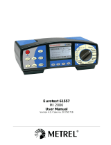
Instaltest 61557
MI 2087
Instruction Manual
Version 3, Code No. 20 750 702

2
Distributor:
Manufacturer:
METREL d.d.
Ljubljanska cesta 77
1354 Horjul
Slovenia
web site: http://www.metrel.si
e-mail: metrel@metrel.si
Mark on your equipment certifies that this equipment meets the requirements of the
EU (European Union) concerning safety and interference causing equipment
regulations
© 2000 METREL
No part of this publication may be reproduced or utilized in any form or by any means
without permission in writing from METREL

MI 2087 Instaltest 61557 Table of contents
2
1. Introduction.............................................................................................................3
1.1. General description ............................................................................................3
1.2. Warnings............................................................................................................4
1.3. List of parameters measurable by the Instaltest 61557......................................5
1.4. Standards applied ..............................................................................................6
2. Instrument description...........................................................................................7
2.1. Front panel.........................................................................................................7
2.2. Connector panel.................................................................................................9
2.3. Bottom side ......................................................................................................10
2.4. Standard accessories.......................................................................................11
2.5. Optional accessories........................................................................................11
2.6. Ways of carrying the instrument.......................................................................11
2.7. Accessories required for specific measurement...............................................12
3. Measurement instructions ...................................................................................13
3.1. Insulation resistance ........................................................................................13
3.2. Varistor Over-voltage Protection Devices ........................................................17
3.3. Continuity of protective conductors ..................................................................20
3.4. Continuity .........................................................................................................24
3.5. RCD - Contact Voltage and Fault Loop Resistance .........................................26
3.6. RCD - Trip-out Time.........................................................................................29
3.7. RCD – Trip-out Current ....................................................................................32
3.8. RCD - Automatic Test ......................................................................................34
3.9. Fault Loop Resistance and Prospective Short-circuit Current ......................39
3.10. Line Resistance RL-N/RL-L and Prospective Short-circuit Current................42
3.11. Voltage Logging .............................................................................................44
3.12. Phase rotation................................................................................................47
3.13. Illumination.....................................................................................................49
3.14. Tracing of electric installation .........................................................................51
4. Memory and other operations .............................................................................53
4.1. Storing of test results .......................................................................................53
4.2. Recalling of stored results................................................................................56
4.3. Erasing of stored results ..................................................................................58
4.4. RS 232 communication ....................................................................................58
4.5. Reset of the instrument ....................................................................................59
5. Maintenance..........................................................................................................60
5.1. Batteries...........................................................................................................60
5.2. Fuses ...............................................................................................................61
5.3. Cleaning...........................................................................................................62
5.4. Periodic calibration...........................................................................................62
5.5. Service .............................................................................................................62
6. Technical specification ........................................................................................63
6.1. Functions..........................................................................................................63
6.2. General characteristics .....................................................................................65

MI 2087 Instaltest 61557 Instrument description
3
1. Introduction
Congratulations on your purchase of the Instaltest 61557 test instrument and it's
accessories, produced by METREL d.d. We are glad, to be able to offer high
professional test equipment, for carrying out absolute inspection of electric
installations in buildings. The equipment was designed and produced on basis of rich
experiences, acquired through more-years long period of dealing with electric
installation test equipment.
1.1. General description
The Instaltest 61557 is high professional, multifunctional, portable test instrument,
intended for carrying out measurements, according to European standard EN 61557,
as well as various other tests and measurements.
The instrument is equipped with all accessories, necessary for comfortable carrying
out the tests. It is kept in a soft carrying bag, together with all the enclosed
accessories.
Electronic part of the Instaltest 61557 is produced in SMD technology, which demands
practically no service interventions. Wide, custom designed display with backlight
offers easy to read main results as well as wide range of subresults, parameters and
messages. Operation is simple and clear; operator does not need any special training
(except to read this Instruction Manual) to operate the instrument.
In order the operator to be familiar enough with measurements in general, it is
advisable to read the enclosed handbook Measurements on electric installations in
theory and practice
Professional PC SW enables simple transfer of test results and other parameters to
PC, as well as automatic forming of final protocols.

MI 2087 Instaltest 61557 Introduction
4
1.2. Warnings
In order to reach high operator’s safety, while carrying out various measurements and
tests using the Instaltest 61557, as well as to keep the test equipment undamaged, it
is necessary to consider the following general warnings:
• If the test equipment is used in manner not specified in this Instruction
Manual, the protection provided by the equipment may be impaired!
• Do not use the instrument and accessories, if any damage is noticed!
• In case of blown any fuse, follow the instructions in this Instruction
Manual, to replace it!
• Service intervention or calibration procedure is allowed to be carried out
only by a competent, authorised person!
• Consider all generally known precautions, in order to avoid risk of electric
shock, while dealing with hazardous voltages!
• Use only standard or optional test cables supplied by your dealer!

MI 2087 Instaltest 61557 Instrument description
5
1.3. List of parameters measurable by the Instaltest 61557
Parameter Switch position Description
Insulation Resistance Ri RISO
- Test voltage: 50 ÷ 1000V
in step of 10V
Continuity R of protective
conductors
R ±200 mA
- Test current > 200 mAd.c.
- Single measurement
- Auto polarity reverse
Continuity Rx R ±200 mA - Test current < 7 mA
- Continuous measurement
Fuse/Fault/Conductor
locator
LOCATOR
- In combination with hand-held
indicator
- Line voltage loading or
imposing of test signal
Fault Loop Resistance RL-PE RLOOP, ISC
UL-PE
- Max. test current 2,5A
Fault Loop Prospective
Short-circuit Current Ipsc
RLOOP, ISC
UL-PE
- Calculation:
Ipsc = UN⋅1,06/RL-PE
Voltage UL-PE RLOOP, ISC
UL-PE
- 0 ÷ 264 V
Line Resistance RL-N RLINE, ISC
UL-N
- Max. test current 2,5A
Line Prospective
Short-circuit Current Ipsc
RLINE, ISC
UL-N
- Calculation:
Ipsc = UN⋅1,06/RL-N
Voltage UL-N RLINE, ISC
UL-N
- 0 ÷ 264 V
Phase rotation
phase rotation
RCD - Contact Voltage Uc Uc,RL - Without test rod
- No trip-out RCD
RCD - Fault Loop Resistance
RL (external source)
Uc, RL - Without test rod
- No trip-out RCD
RCD - Trip-out Time t∆
∆∆
∆N t∆N - At 0,5I∆N, I∆N, 2I∆N and 5I∆N
RCD – Trip-out Current I∆
∆∆
∆ I∆, t∆ - Rising current
(0,2 ÷ 1,1)I∆N
RCD - Trip-out Time t∆
∆∆
∆ at
Trip-out Current I
∆
∆∆
∆
I
∆, t∆
RCD - Automatic test
RCDAUTO
- Contact voltage meas.
- Trip-out time measurement at
0,5I∆N, I∆N and 5I∆N (both test
curr. start phases)
Illumination SENSOR
Varistor Over-voltage Device
- Breakdown Voltage Ub
varistor TEST - Rising test voltage
0 ÷ 1000 Vd.c.
UL-N Voltage Recording UL-N LOG
- 1 ÷ 1999 samples
- sampling rate 1 ÷ 99 s

MI 2087 Instaltest 61557 Instrument description
6
1.4. Standards applied
The Instaltest 61557 is designed according to European safety standard
♦ EN 61010 – 1
EMC (noise and immunity) according to European standards
♦ EN 50081 – 1
♦ EN 50082 – 1
Measurements according to European standard EN 61557:
♦ Insulation Resistance................................................................... Part 2
♦ Loop Resistance .......................................................................... Part 3
♦ Resistance of earth connection and equipotential bonding.......... Part 4
♦ Residual Current Devices (RCD) in TT and TN systems ............. Part 6
♦ Phase Sequence.......................................................................... Part 7
Illumination measurement according to standard
♦ DIN 5032....................................................................................... Part 7

MI 2087 Instaltest 61557 Instrument description
7
2. Instrument description
2.1. Front panel
1231514131211
10987
6
5
4
METREL
Inst altest 61557
LOCATOR
U
CL
,
R
R
LI NE
SC
,
I
R
LO O P SC
,
I
U
L- N
U
L- PE
t
DN
U
L- N
LOG
I
DD
,
t
RCD
AUTO
9
8
7
6
10
11
12
1
2
3
R
±
200mA
4
5
SENSOR
Fig. 1. Front panel

MI 2087 Instaltest 61557 Instrument description
8
Legend:
1 ON/OFF key, to switch ON or OFF the instrument. Auto OFF will occur
automatically 10 minutes after last strike to any key or function switch
rotation.
2 RS 232 key, to communicate with PC.
3 LAMP key, to turn ON or OFF display backlight. Auto OFF will automatically
occur 20 seconds after last strike to any key or function switch rotation.
4 RCL key, to recall stored results.
5 SAVE key, to store test results.
6 START key, to start any measurement.
7 CLR key, to erase stored results.
8 DISPLAY key, to:
• Check last actual test voltage (RINS position), after finishing the
measurement.
• Switch between Continuity of protective conductors and General Continuity
functions (R ±
±±
±200mA position).
• Check lower partial result in Continuity of protective conductors function,
when main test result is displayed (R ±
±±
±200mA position).
• Switch between Voltage and Frequency measurement (RLINE, Isc UL-N or
RLOOP, Isc UL-PE position), before START key is pressed.
• Check Prospective Short-circuit Current Ipsc (RLINE, Ipsc UL-N or RLOOP,
Ipsc UL-PE position), when main test result is displayed.
• Check Fault Loop Resistance value and set Limit Contact Voltage (Uc, RL
position), when result Uc is displayed.
• Check Contact Voltage and set Limit Contact voltage (t∆
∆∆
∆N position), when
result t∆N is displayed.
• Check Contact Voltage, Trip-out Time at trip-out current and set Limit
Contact Voltage (I∆
∆∆
∆, t∆
∆∆
∆ position), when result I∆ is displayed.
• Check Lowest, Highest and Average value of Recorded voltage as well as
Set parameters (U
L-N LOG position), after the measurement is finished.
9 LCD with backlight.
10 Function switch, to select appropriate parameter to be tested.
11 Belt slot, to fix carrying belt.
12 CAL key, to compensate resistance of test leads in R
±
±±
±200mA function.
13 ↓
↓↓
↓ key, to reduce settable parameter value.
14 ↑
↑↑
↑ key, to increase settable parameter value.
15 SELECT key, to select/set function parameters as follows:
• Insulation Resistance (Nominal test voltage and Low limit value of test
result).
• Continuity of protective conductors (High limit value of test result).
• Contact Voltage (Nominal differential current, RCD type and Limit contact
voltage).

MI 2087 Instaltest 61557 Instrument description
9
• Trip-out Time (Nominal differential current, Multiplier of Nominal differential
current and RCD type).
• Trip-out current (Nominal differential current).
• AUTO RCD test (Nominal differential current and RCD type).
• Voltage Logging (Period between sampling and Total number of samples).
• Varistor breakdown voltage (High and Low limit value of test result).
• Illumination (Low limit value of measured result).
2.2. Connector panel
Fig. 2. Connector panel
Legend:
1 Main test connector
2 Protection connector cover (protects simultaneous connection of test and
RS232 cable)
3 RS 232 connector (to connect Instaltest 61557 to PC)

MI 2087 Instaltest 61557 Instrument description
10
2.3. Bottom side
Fig. 3. Bottom side
Legend:
1 Nylon strip (it serves the operator to carry the instrument hung on his neck).
2 Auxiliary nylon strip (it serves the operator to fix the instrument along his body).
3 Plastic cover (it fixes nylon strip to the instrument). There is a screw under the
cover, which is to be unscrewed, when opening the instrument for service or
calibration purpose.
4 Screw (unscrew it, to remove carrying strip or to open the instrument).
5 Label with measurement ranges.
6 Battery/fuse compartment cover.
7 Screw (unscrew it to replace batteries or blown fuse.
8 Rubber foot.

MI 2087 Instaltest 61557 Instrument description
11
2.4. Standard accessories
See attached sheet, to compare received set of accessories with listed one.
2.5. Optional accessories
See attached sheet, to check the list of possible optional accessories, which may be
supplied upon request.
2.6. Ways of carrying the instrument
As two carrying belts (neck and back) are supplied in standard set, various possibilites
of carring the instrument are available. Operator can choose appropriate one on
bases of his operation, see the folloving examples:
The instruments is hung
around operator´s neck only –
quick placing and displacing.
The instruments is hung
around operator´s neck and
fixed to this body with back
belt – stable position.
The instrument can be used even placed in
soft carrying bag – test cable connected to
the instrument throught the side aperture.
The instrument
is fixed to
operator´s bodi
with back belt
only – it can be
simply moved
from side to
front position for
measurement
purpose and
back again.

MI 2087 Instaltest 61557 Instrument description
12
2.7. Accessories required for specific measurement
The table below presents accessories (standard or optional) required for specific
measurement. The accessories marked as optional may also be standard ones in
some set configurations; Please see attached list of standard accessories for your set
configuration or contact your dealer for further information.
FUNCTION REQUIRED ACCESSORIES
Insulation Resistance
- Universal Test Cable or
Tip Commander (Option – Order No. A 1002)
Continuity of Protective Conductor
- Universal Test Cable or
Tip Commander (Option – Order No. A 1002)
- Probe Test Lead 4m (Option – Order No. A 1012)
Continuity
- Universal Test Cable or
Tip Commander (Option – Order No. A 1002)
Fault Loop Resistance, Ipsc
- Universal Test Cable or
Plug Commander (Option – Order No. A 1001)
Line Resistance, Ipsc
- Universal Test Cable or
Plug Commander (Option – Order No. A 1001)
RCD – Contact Voltage at I∆
∆∆
∆N
RCD – Trip-out Time
RCD – Trip-out Current
RCD – Fault Loop Resistance
RCD – Automatic Test
- Universal Test Cable or
Plug Commander (Option – Order No. A 1001)
Phase Rotation
- Universal Test Cable or
Three-phase Cable (Option – Order No. A 1110) or
Three-phase Adapter (Option – Order No. A 1111)
Fuse, Fault, Conductor Tracing
- Universal Test Cable
- Fuse / Fault / Conductor Locator (Option – Order No. A 1005)
Varistor Overvoltage Device –
Breakdown Voltage
- Universal Test Cable
Illumination
- LUXmeter probe type B (Option – Order No. A 1102)
- LUXmeter probe type C (Option – Order No. A 1119)
Voltage Logging
- Universal Test Cable or
Plug Commander (Option – Order No. A 1001) or
Tip Commander (Option – Order No. A 1002)

MI 2087 Instaltest 61557 Measurement instructions
13
3. Measurement instructions
3.1. Insulation resistance
There are different objects, where insulation resistance is to be measured, in order to
assure safety against electric shock. Let’s list a few examples:
• Insulation resistance between installation conductors (all combinations).
• Insulation resistance of non-conductive rooms (walls and floors).
• Insulation resistance of ground cables.
• Resistance of semiconductive (antistatic) floors.
For additional general information concerning Insulation Resistance measurement,
refer to enclosed handbook Measurements on electric installations in practice and
theory.
Warnings!
• Make sure tested object to be deenergised (mains voltage disconnected),
before starting the measurement!
• When measuring Insulation Resistance between conductors, all loads
must be disconnected and all switches closed!
• Do not touch tested object while testing it, risk of electric shock!
• Do not connect test terminals to external voltage higher than 600 V a.c. or
d.c., in order not to damage the test instrument!
• In case of capacitive test object (capacitive compensation of reactive
power, long tested cable etc.), automatic discharge of the object may not
be done immediately after finishing the measurement. Falling voltage will
be displayed in that case – do not disconnect test leads until the voltage
drops below 50V or carefully discharge the tested object manually!
How to carry out the measurement?
Step 1
• Connect test cable (Universal test cable or Tip Commander) to Instaltest 61557.
• Set function switch to RISO position, the following menu will be displayed:
Fig. 4. Insulation Resistance initial menu

MI 2087 Instaltest 61557 Measurement instructions
14
Step 2
• Set Nominal Test Voltage.
How to set the Test Voltage?
• Press the SELECT key twice and release it, to enter “Test voltage adjustment
mode”, the following menu will be displayed:
Fig. 5. Test voltage adjustment menu and the Table of available nominal test voltages
• Use the ↑
↑↑
↑ and ↓
↓↓
↓ keys, to set required Nominal test voltage. Individual strike will
increase/decrease the voltage for one step, while continuous pressure will
increase/decrease it continuously (the value will stop for a while, when reaching
standard value like 100, 250 or 500 V, enabling the operator to depress used
key).
Step 3
• Set Low Limit Insulation Resistance Value. Later will test results be compared
with the set limit value and, if lower, they will be equipped with “!” mark.
How to set the Low Limit Value?
• Press the SELECT key after setting Nominal test voltage, to enter “Low Limit
Value adjustment menu”; see the figure below:
Last set Nominal test voltage is
blinking.
Available nominal
test voltages (V)
Step
(V)
50 ÷ 1000
10

MI 2087 Instaltest 61557 Measurement instructions
15
Last set Low limit value is blinking.
Fig. 6. Low Limit Value adjustment menu and the Table of available limit values
• Use the ↑
↑↑
↑ and ↓
↓↓
↓ keys, to set required Low Limit Value. Individual strike will
increase/decrease the value for one step, while continuous pressure will
increase/decrease it continuously. If test results are not to be compared with
Low Limit Value at all then press the CLR key, no will be displayed instead of
set value.
• Press the SELECT key again after setting limit value, to return to “Insulation
Resistance initial menu”.
Step 4
• Connect test cable to tested object, according to the figure below:
Fig. 7. Connection of Universal Test Cable and optional Tip Commander
(Order No. A 1002)
Step 5
• Press the START key and keep it pressed, until result is stabilised, then release
the key. Last result will stay displayed.
• Check last actual test voltage pressing the DISPLAY key.
• Store displayed result for documentation purpose; see instructions how to store
it in chapter 4.1. Storing of test results.
Available low limit
values (MΩ)
Step
(MΩ)
0,01 ÷ 0,25
0,01
0,25 ÷ 1
0,05
1 ÷ 10
1
10 ÷ 200
10
L1
L2
L3
N
PE
switched off
mains voltage
closed
switches
disconnec-
ted loads
Option
A 1002
N/L2
L
/
L
1
PE/L3

MI 2087 Instaltest 61557 Measurement instructions
16
Notes!
• In case of present external voltage higher than 29 V a.c./d.c. between test
terminals, the Insulation Resistance measurement will not be carried out after
pressing START key, but the voltage will be displayed, equipped with “!” mark!
Beep warning sound will be affected too.
• Tested object is discharged automatically after finishing the measurement,
actual voltage is displayed during discharging, until the voltage drops below
30 V!
• If test result is out of measurement range (open test leads or good isolation),
>1000 MΩ
ΩΩ
Ω message will be displayed (UN ≥ 250 V) or >200 MΩ
ΩΩ
Ω (UN < 250 V)!
• Positive pole of test voltage is attached to blue test lead (Universal test cable) or
to commander test tip (Tip Commander)!
• bat message, displayed during or after finishing the measurement means
batteries are too weak to guarantee correct result. Replace the batteries.

MI 2087 Instaltest 61557 Measurement instructions
17
3.2. Varistor Over-voltage Protection Devices
For general information concerning the measurement, refer to enclosed handbook
Measurements on electric installations in practice and theory.
How to carry out the Breakdown voltage measurement?
Step 1
• Connect Universal test cable to Instaltest 61557.
Note!
Set function switch to Riso position and press the SELECT key to enter the selection
menu. Use the ↑and ↓ keys to select between “ISO” (Insulation resistance) and
“tSt” (Varistor Over-voltage Protection Devices) functions. Press SELECT key when
“tSt” is displayed to enter the Varistor Over-voltage Protection Devices function. Press
the SELECT key twice to skip limit adjustment menus and to enter Varistor test initial
menu.
Fig. 8. Varistor Test initial menu
Step 2
• Set High Limit Breakdown Varistor Voltage. Later will test results be
compared with the set limit value and, if higher, they will be equipped with “!”
mark.
How to set the High Limit value?
• Press the SELECT key twice, to enter “High Limit value adjustment mode”, the
following menu will appear:
Fig. 9. High limit value adjustment menu and the table of available limit values
Last set High limit value is blinking.
Available
values (V)
Step
(V)
0 ÷ 1000
10

MI 2087 Instaltest 61557 Measurement instructions
18
• Use the ↑
↑↑
↑ and ↓
↓↓
↓ keys, to set required High Limit Value. Individual strike will
increase/decrease the value for one step, while continuous pressure will
increase/decrease it continuously. If test results are not to be compared with
High Limit Value at all, then press the CLR key, no will be displayed instead of
set value.
Step 3
• Set Low Limit Breakdown Varistor Voltage. Later will test results be
compared with the set limit value and, if lower, they will be equipped with “!”
mark.
How to set the Low Limit Value?
• Press the SELECT key after setting the High Limit Value, to enter “Low Limit
Value adjustment mode”, the following menu will be displayed:
Fig. 10. Low limit value adjustment menu and the table of available limit values
• Use the ↑
↑↑
↑ and ↓
↓↓
↓ keys, to set required Low Limit Value. Individual strike will
increase/decrease the value for one step, while continuous pressure will
increase/decrease it continuously. If test results are not to be compared with
Low Limit Value at all, then press the CLR key, no will be displayed instead of
set value.
• Press the SELECT key again after setting the limit values, to return to “Varistor
Test initial menu”.
Step 4
• Connect Universal test cable to tested Varistor Over-voltage Protection
Device, according to the figure below.
Fig. 11. Connection of Universal Test Cable
Last set Low limit value is blinking.
Available
values (V)
Step
(V)
0 ÷ 1000
10

MI 2087 Instaltest 61557 Measurement instructions
19
Step 5
• Press the START key and release it. Test voltage starts to rise (500 V/s) and as
soon as varistor’s forward current reaches the value of 1 mA (Breakdown
Voltage is defined at that current), the voltage will be displayed. Generator will
stop to generate test voltage.
• Check the Breakdown voltage scaled to a.c. value called Uac pressing the
DISPLAY key.
Meaning of the Uac voltage:
Protection devices intended for a.c. network are usually dimensioned approx. 20% of
nominal mains voltage above peak value of nominal mains voltage.
Example:
Nominal mains voltage Un = 230V
Upeak = 230V⋅1,41 = 324V
Ubreakdown = (Upeak + 0,2⋅Un) ≅ Un⋅1,6 = 368V
Uac voltage may be directly compared with the voltage declared on tested protection
device.
• Store displayed result for documentation purpose; see instructions how to store
it in chapter 4.1. Storing of test results.
Notes!
• In order test result not to be influenced by connected loads, tested Over-voltage
Protection Device must be removed from installation, before testing it.
• If the Over-voltage Protection Device to be tested is not possible to be removed
from installation (permanent connection), make sure to disconnect all other
elements connected to installation, which may influence on test result.
bat message, displayed during or after finishing the measurement means batteries
are too weak to guarantee correct result. Replace the batteries.
/