Page is loading ...

The Complete Networking Solution
MRX/MRX-2 AND
MRXI/MRXI-2
10BASE-T HUB
INSTALLATION GUIDE
CABLETRON SYSTEMS, P.O. Box 5005, Rochester, NH 03867-5005
INC.

NOTICE
i
NOTICE
Cabletron Systems reserves the right to make changes in
specifications and other information contained in this document
without prior notice. The reader should in all cases consult Cabletron
Systems to determine whether any such changes have been made.
The hardware, firmware, or software described in this manual is
subject to change without notice.
IN NO EVENT SHALL CABLETRON SYSTEMS BE LIABLE FOR
ANY INCIDENTAL, INDIRECT, SPECIAL, OR CONSEQUENTIAL
DAMAGES WHATSOEVER (INCLUDING BUT NOT LIMITED TO
LOST PROFITS) ARISING OUT OF OR RELATED TO THIS
MANUAL OR THE INFORMATION CONTAINED IN IT, EVEN IF
CABLETRON SYSTEMS HAS BEEN ADVISED OF, KNOWN, OR
SHOULD HAVE KNOWN, THE POSSIBILITY OF SUCH
DAMAGES.
© Copyright March 1991 by:
Cabletron Systems, Inc.
P.O. Box 5005, Rochester, NH 03867-5005
All Rights Reserved
Printed in the United States of America
Order number: 9030313 March 91
MRX, MRX-2, MRXI, MRXI-2, LANVIEW, SPIM-T, SPIM-T1,
TMS-3, FOT-F, TPT-T, SPIM-F1, SPIM-F2, SPIM-C, SPIM-A,
Remote LANVIEW/Windows, SPECTRUM, and LAN-MD are
trademarks of Cabletron Systems, Inc.

FCC NOTICE
ii
FCC NOTICE
This device complies with Part 15 of FCC rules. Operation is subject
to the following two conditions: (1) this device may not cause harmful
interference, and (2) this device must accept any interference re-
ceived, including interference that may cause undesired operation.
WARNING: This equipment uses and generates and can radiate
radio frequency energy and if not installed properly and used in
accordance with the instruction manual, may cause interference to
radio communications. It has been tested and found to comply with
the limits for a Class A digital device pursuant to Part 15 of FCC
Rules, which are designed to provide reasonable protection against
such interference in a commercial environment. Operation of this
equipment in a residential area is likely to cause interference in
which case the user at his own expense will be required to take
whatever steps may be necessary to correct the interference.
If this equipment does cause interference to radio or television,
which can be determined by turning the equipment off and on, the
user is encouraged to try to correct the interference by one or more of
the following measures:
• Re-orient the receiving antenna.
• Relocate the antenna with respect to the MRX/MRXI.
• Move the MRX/MRXI away from the antenna.
• Plug the MRX/MRXI into a different outlet so that the
MRX/MRXI and the receiver are on different branch circuits.
If necessary, the user should consult the dealer or an experienced
radio/ television technician for additional suggestions. The user may
find the following booklet prepared by the Federal Communication
Commission helpful:
“How to Identify and Resolve Radio TV Interference Problems”
This booklet is available from the U.S. Government Printing Office,
Washington D.C. 20402 - Stock No. 004-000-00345-4.
ii

CONTENTS
iii
CONTENTS
CHAPTER 1 INTRODUCTION
1.1 Using This Manual ..................................................................... 1-2
1.2 The 10BASE-T HUB................................................................... 1-2
1.3 Related Manuals ......................................................................... 1-4
1.4 Getting Help................................................................................ 1-4
CHAPTER 2 INSTALLATION REQUIREMENTS/
SPECIFICATIONS
2.1 Network Requirements............................................................... 2-1
2.2 Selecting A Location For The HUB............................................ 2-1
2.3 Network Guidelines .................................................................... 2-2
2.3.1 10BASE-T Twisted Pair Network Requirements ...........2-2
2.3.2 Fiber Optic Network Requirements ................................ 2-4
2.3.3 Thin-Net Network Requirements .................................... 2-4
2.3.4 Transceiver/AUI Requirements ....................................... 2-5
2.4 Operating Specifications............................................................. 2-6
CHAPTER 3 INSTALLATION
3.1 Unpacking The HUB .................................................................. 3-1
3.2 Attaching The Strain Relief Bracket ......................................... 3-2
3.3 Installing The HUB .................................................................... 3-2
3.3.1 Rack Mounting The HUB ................................................ 3-2
3.3.2 Wall Mounting The HUB ................................................. 3-4
3.3.3 Free-Standing Installation .............................................. 3-7
3.4 Connecting The HUB To The Power Source.............................. 3-7
3.5 Connecting The HUB To The Ethernet Network......................3-8
3.5.1 Connecting The Network Port Cabling (MRX/MRXI).....3-8
3.5.2 Connecting The Network Port Cabling
(MRX-2/MRXI-2)............................................................... 3-8
3.5.3 Connecting A Twisted Pair Segment To A SPIM-T ........3-9
3.5.4 Connecting A Shielded Twisted Pair Segment
To A SPIM-T1 ................................................................. 3-10

CONTENTS
iv
CONTENTS (cont.)
CHAPTER 3 (cont.)
3.5.5 Connecting A Fiber Optic Link Segment To A
SPIM-F1Or SPIM-F2 ..................................................... 3-11
3.5.6 Connecting A Thin-Net Segment To A SPIM-C............3-14
3.5.7 Connecting An AUI Cable To A SPIM-A.......................3-15
3.6 Finishing The Installation........................................................ 3-16
CHAPTER 4 TESTING AND TROUBLESHOOTING
4.1 Installation Check-Out ............................................................... 4-1
4.2 Testing Segments Attached To The HUB.................................. 4-2
4.3 Using LANVIEW ........................................................................ 4-5
CHAPTER 5 ADDING/REPLACING SPIMs
5.1 Opening The HUB ...................................................................... 5-1
5.2 Removing A SPIM....................................................................... 5-2
5.3 Installing A SPIM ....................................................................... 5-2
APPENDIX TWISTED PAIR WIRING GUIDE
A.1 Attaching Twisted Pair Segments To The HUB ...................... A-1

INTRODUCTION
Page 1-1
CHAPTER 1
INTRODUCTION
Welcome to the Cabletron Systems MRX/MRX-2 and MRXI/MRXI-2
10BASE-T HUB Installation Guide. This manual covers
installation instructions and provides reference information for the
following Cabletron Systems 10BASE-T Hubs:
• MRX
- 12-10BASE-T (using 50-pin Champ connector)
- 2 Single Port Interface Module (SPIM) slots
- No Management
• MRX-2
- 12-10BASE-T (using RJ-45 connectors)
- 2 Single Port Interface Module (SPIM) slots
- No Management
• MRXI
- 12-10BASE-T (using 50-pin Champ connector)
- 2 Single Port Interface Module (SPIM) slots
- SNMP Compliant Management
• MRXI-2
- 12-10BASE-T (using RJ-45 connectors)
- 2 Single Port Interface Module (SPIM) slots
- SNMP Compliant Management
NOTE: The term HUB is used throughout this manual when
describing features and functions that are common to all of the devices
listed above. The terms MRX, MRX-2, MRXI and MRXI-2 are only
used when it is necessary to describe features that are unique to a
specific device.
All four HUBs can serve as a repeater to allow expansion of existing
802.3 networks using a variety of media. All four HUBs are
10BASE-T and 802.3 compliant.

INTRODUCTION
Page 1-2
The MRX is functionally identical to the MRX-2 and the MRXI is
functionally identical to the MRXI-2. The MRX and MRXI provide a
50-pin Champ connector for ports 1 through 12, and the MRX-2 and
MRXI-2 provide twelve RJ-45 connectors.
The MRX/MRX-2 and MRXI/MRXI-2 are functionally the same,
except that the MRXI/MRXI-2 provides the capability of in-band and
out-of-band network management. The MRX/MRX-2 is not
accessible, either in-band or out-of-band, by network management.
1.1 USING THIS MANUAL
Prior to installing and operating the HUB, read through this manual
completely to familiarize yourself with its content and to gain an
understanding of the features of the HUB. A general working
knowledge of Ethernet and IEEE 802.3 type data communications
networks and their physical layer components will be helpful when
installing the HUB.
Chapter 1, Introduction, covers using this document, briefly
describes features of the HUB and concludes with a list of related
manuals.
Chapter 2, Requirements/Specifications, contains requirements
for locating and installing the HUB and operating specifications for
the MRX and MRXI.
Chapter 3, Installation, contains step-by-step installation
instructions that include mounting and cabling for your HUB.
Chapter 4, Testing and Troubleshooting, contains procedures for
checking for the proper installation of the HUB and a description of
the LANVIEW ™ LEDs and their function.
Chapter 5, Adding/Replacing SPIMs, describes removing and
installing optional SPIM boards in the HUB.
Appendix, Twisted Pair Wiring Guide, serves as an aid to wiring
punch-down blocks and twisted pair segments between your HUB
and 10Base-T Ethernet devices.

INTRODUCTION
Page 1-3
1.2 THE 10BASE-T HUB
The Cabletron Systems HUB provides twelve 10BASE-T compliant
ports (via 50 pin Champ connector) and two slots that support
Cabletron Systems’ Single Port Interface Modules (SPIM). A variety
of SPIMs are available permitting the expansion of an Ethernet/802.3
network via:
• Unshielded Twisted Pair Cable from the 10BASE-T Twisted Pair
Interface Modules (SPIM-T).
• Shielded Twisted Pair Cable from the 10BASE-T Twisted Pair
Interface Modules (SPIM-T1).
• Fiber Optic Cable, with SMA or ST connectors, from the Fiber
Optic Interface Modules (SPIM-F1 or SPIM-F2).
• Thin-Net Cable from the Coaxial Interface Module (SPIM-C).
• AUI Cable, to an external transceiver, from the AUI Interface
Module (SPIM-A).
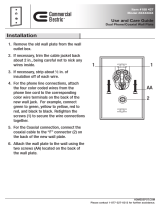
Figure 1-1. MRX, MRX-2, MRXI and MRXI-2 10BASE-T HUBs

INTRODUCTION
Page 1-4
The HUB fully conforms to the IEEE 802.3 Repeater, AUI and
10BASE-T specifications, and provides the flexibility to connect
networks using IEEE 802.3, Ethernet Version 1 or Version 2
equipment. As an IEEE 802.3 compliant repeater, the HUB
transmits re-timed data packets, regenerates the preamble, extends
fragments, arbitrates collisions and automatically partitions problem
segments, and reconnects non-problem segments. This feature
minimizes the impact on network operation resulting from a problem
on one segment by isolating the problem segment so that only the
devices on that segment are affected. When the problem is solved, the
problem segment is automatically reconnected to the network.
Since the HUB utilizes polarity detection and correction, the twisted
pair connections are not sensitive to signal polarity. The network will
still function properly with the (+) and (–) lines within a pair
reversed. The LINK LED for the port with reversed polarity will
flash to indicate this condition. Operating in this condition is not
recommended and if this condition is discovered, the segment should
be removed from the network and wired correctly by a technician.
This reduces the potential for problems in the future if equipment
changes are made. Connector pinouts are provided in Chapter 2,
Installation Requirements/Specifications.
All four HUBs incorporate Cabletron Systems’ LANVIEW™ status
monitoring and diagnostic system. LANVIEW is a convenient
troubleshooting tool that allows you to monitor power, and data
activity and help you diagnose power failures, collisions, cable faults,
and link problems.
The MRXI provides an RS-232 Console port (not available in the
MRX) that supports a Digital Equipment Corporation™, VT220™ or
PC emulation of the VT220™ terminal. The terminal serves as a
local management console, providing out-of-band access to MRXI/
LM™, Local Management for the Cabletron Systems MRXI/MRXI-2.
MRXI/LM is an effective menu driven tool that presents screens that
integrate network status and network control. Several menus permit
the network manager to manage and monitor the flow of traffic and
access a summary of errors to pinpoint potential problem areas in a
network. This capability gives the network manager the ability to
interpret status and establish parameters to obtain optimal
performance for the network and, if necessary, permit diagnosis of
network problems. For additional information, refer to the
MRXI/LM, Local Management for the Cabletron Systems
MRXI/MRXI-2, User’s Manual.

INTRODUCTION
Page 1-5
The MRXI/MRXI-2 can also be controlled and managed in-band using
Cabletron Systems’ LANVIEW/Windows, SPECTRUM, and SNMP
network control management software.
1.3 RELATED MANUALS
The manuals listed below should be used to supplement the
procedures and other technical data provided in this manual. The
procedures contained in these manuals will be referenced where
appropriate, rather than repeated.
MRXI/LM, Local Management for the Cabletron Systems
MRXI/MRXI-2, User’s Manual.
Cabletron Systems’ LAN-MD Portable Ethernet Tester User’s
Manual.
1.4 GETTING HELP
If additional support is needed related to the Cabletron Systems
HUB, or if you have any comments, suggestions, or questions relating
to this manual contact Cabletron Systems Technical Support at:
Cabletron Systems, Inc.
P.O. Box 5005
Rochester, NH 03867-5005
Phone: (603) 332-9400

INTRODUCTION
Page 1-6

REQUIREMENTS/SPECIFICATIONS
Page 2-1
CHAPTER 2
INSTALLATION
REQUIREMENTS/SPECIFICATIONS
This Chapter describes the network and power requirements and
operating specifications for the MRX, MRX-2, MRXI, and MRXI-2
10BASE-T HUBs. Before you attempt to install any of these HUBs,
review the installation requirements and operating specifications
that are outlined in this chapter. Your network installation must
meet the conditions, guidelines, specifications, and requirements
included in this chapter to obtain satisfactory performance from this
equipment. Failure to follow these guidelines could produce poor
network performance.
2.1 NETWORK REQUIREMENTS
Take care in planning and preparing the cabling and connections for
your network. The quality of the connections, the length of cables
and other conditions of the installation are critical factors in
determining the reliability of your network. The following sections
describe the network requirements to operate this equipment.
2.2 SELECTING A LOCATION FOR THE HUB
The HUB can be rack mounted, wall mounted, or placed on any
horizontal surface. If not installed in a 19-inch rack, the following
requirements must be met when selecting a location for your HUB.
NOTE: Be sure that the location selected is within reach of the
network cabling.
• An unrestricted free surface area 21 inches wide, 18 inches deep
and 6 inches high is needed.
• A single phase 120 Vac, 15A, grounded power receptacle must be
located within 7 feet of the site.

Page 2-2
REQUIREMENTS/SPECIFICATIONS
• If a shelving unit is to be used, it must be able to support
30 pounds of static weight.
• The temperature for the selected location must be maintained
between 5° and 50° C, and less than 10° C per hour temperature
change.
2.3 NETWORK GUIDELINES
The following network design guidelines must be followed when
connecting the HUB to your network:
• As a general rule, 130 meters is the maximum length for an
unshielded twisted pair segment. However, losses introduced by
connections at punch-down blocks and other equipment serve to
reduce this limit. In most installations, the optimal unshielded
twisted pair length is 100 meters using standard PVC phone wire.
Maximum link length is largely dependent on cable quality. If
high quality, low attenuation cable is used, link lengths of up to
200 meters are achievable.
• The device at the other end of the twisted pair segment must
meet IEEE 802.3 10BASE-T specifications.
• The transceivers that will be connected to the HUB (via a
SPIM-A) must meet IEEE 802.3 standards and must not have the
SQE test function enabled.
2.3.1 10BASE-T Twisted Pair Network Requirements
When connecting a 10BASE-T Twisted Pair Segment at any of the
10BASE-T Twisted Pair HUB Ports (Ports 1 through 12, a Single Port
10BASE-T Twisted Pair Segment Interface module [SPIM-T or
SPIM-T1]), the following network requirements must be met:
• Length - The IEEE 802.3 10BASE-T standard requires that
10BASE-T devices transmit over a 100 meter (328 foot) link using
22-24 AWG unshielded twisted pair wire.

REQUIREMENTS/SPECIFICATIONS
Page 2-3
As a general rule, links up to 130 meters in length for unshielded
twisted pair and 200 meters in length for shielded twisted pair
are achievable. For each connector or patch panel in the link,
subtract 12 meters from the 150 meter limit. This will allow for
links of up to 126 meters using standard 24 AWG UTP wire and
two patch panels within the link. Higher quality low attenuation
cables may be required when using links of greater than 126
meters. Due to cable delay, the maximum link length is always
limited to 200 meters, regardless of the cable type.
• Insertion Loss - The maximum insertion loss allowed for a
10BASE-T link is 11.5 dB at all frequencies between 5.0 and 10
MHz. This includes the attenuation of the cables, connectors,
patch panels, and reflection losses due to impedance mismatches
in the link segment.
• Impedance - Unshielded twisted pair cables typically have an
impedance of between 85 to 110 ohms. Shielded twisted pair
cables, such as IBM Type 1 cable, can also be used. You should
remember that the impedance of IBM Type 1 cable is typically
150 ohms. This increases the signal reflection caused by the
cable, but since the cable is shielded, this signal reflection has
little effect on the received signal’s quality due to the lack of
crosstalk between the shielded cable pairs. Cabletron Systems’
10BASE-T Twisted Pair products will work on twisted pair cable
with 75 to 165 ohms impedance.
• Jitter - Intersymbol interference and reflections can cause jitter
in the bit cell timing, resulting in data errors. A 10BASE-T link
must not generate more than 5.0 nsec. of jitter. If your cable
meets the impedance requirements for a 10BASE-T link, jitter
should not be a concern.
• Delay - The maximum propagation delay of a 10BASE-T link
segment must not exceed 1000 nsec. This 1000 nsec. maximum
delay limits the maximum link segment length to no greater than
200 meters.
• Crosstalk - Crosstalk is caused by signal coupling between the
different cable pairs contained within a multi-pair cable bundle.
10BASE-T transceivers are designed so that the user does not
need to be concerned about cable crosstalk, provided the cable
meets all other requirements.

Page 2-4
REQUIREMENTS/SPECIFICATIONS
• Noise - Noise can be caused by either crosstalk or externally
induced impulses. Impulse noise may cause data errors if the
impulses occur at very specific times during data transmission.
Generally, the user need not be concerned about noise. If noise-
related data errors are suspected, it may be necessary to either
reroute the cable or eliminate the source of the impulse noise.
• Temperature - Multi-pair PVC 24 AWG telephone cables
typically have an attenuation of approximately 8 to 10 dB/100 m
at 20° C (78° F). The attenuation of PVC insulated cable varies
significantly with temperature. At temperatures greater than
40° C (104° F), it is strongly recommended that you use plenum-
rated cables to ensure that cable attenuation remains within
specification.
2.3.2 Fiber Optic Network Requirements
When connecting a Fiber Optic Link Segment to the HUB with a
Single Port Fiber Optic Interface module (SPIM-F1 or SPIM-F2), the
following network requirements must be met:
• Cable Type - The SPIM-F1 and SPIM-F2 are designed for use
with one of the following multimode fiber optic media:
- 50/125 µm fiber optic cabling.
- 62.5/125 µm fiber optic cabling.
- 100/140 µm fiber optic cabling.
• Attenuation - The fiber optic cable must be tested with a fiber
optic attenuation test set that is adjusted for an 850 nm
wavelength. This test verifies that the signal loss in a cable is
within an acceptable level:
- 13.0 dB or less for 50/125 fiber cable segment.
- 16.0 dB or less for 62.5/125 fiber cable segment.
- 19.0 dB or less for 100/140 fiber cable segment.

REQUIREMENTS/SPECIFICATIONS
Page 2-5
• Budget and Propagation Delay - When determining the
maximum fiber optic cable length, the fiber optic budget delay
and total network propagation should be calculated and taken
into consideration before fiber optic cable runs are incorporated in
any network design. Fiber optic budget is the combination of the
optical loss due to the fiber optic cable, in-line splices, and fiber
optic connectors. Propagation delay is the amount of time it takes
a packet to travel from the sending device to the receiving device.
• Length - The maximum allowable fiber optic cable length is 2
km. However, IEEE 802.3 specifications allow for a maximum of
1 km.
2.3.3 Thin-Net Network Requirements
When connecting a Thin-net segment to the HUB with a Single Port
Coax Interface Module (SPIM-C), the following network requirements
must be met:
• Cable Type - 50 ohm RG-58A/U type coaxial cable must be used
when making up a thin-net cable segment.
• Length - The thin-net segment must be no longer than
185 meters.
• Terminations - A 50 ohm terminator must be connected to the
far end of each thin-net segment.
• Connections - A maximum of 29 tee-connectors may be used
throughout the length of cable segment for host connections. If
an excessive number of barrel connectors are used within the
cable segment, such as finished wall plates with BNC feed-
throughs, then a reduced number of host connections may be
required. For special network design, contact Cabletron Systems
Technical Support.
• Grounding - For safety, only one end of a thin-net segment
should be connected to earth ground. Connection to earth ground
at more than one point on the segment could produce dangerous
ground currents.

Page 2-6
REQUIREMENTS/SPECIFICATIONS
WARNING: Do not connect the shield at both ends of a thin net
segment to ground. Only one end of the shield should be connected
to earth ground.
The BNC ports of the Coaxial Interface Modules are not
connected to earth ground.
2.3.4 Transceiver/AUI Requirements
When connecting an external network segment, via a transceiver and
an AUI cable, to the HUB with a Single Port AUI Interface module
(SPIM-A), the following network requirements must be met:
• Transceiver/Ethernet Device - The transceiver or Ethernet
Device to which the module will be connected must meet IEEE
802.3 standards, and/or Ethernet Version 1.0 or Version 2.0
requirements.
• AUI Cable - The AUI cable connecting the module to a device
must be IEEE 802.3 type cable.
• Length - The AUI Cable must not exceed 50 meters in length. If
28 AWG thin office drop AUI cable is used, then the maximum
cable length is limited to 50 feet (15.24 meters).

REQUIREMENTS/SPECIFICATIONS
Page 2-7
2.4 OPERATING SPECIFICATIONS
The operating specifications for the Cabletron Systems’ HUB are
described in this section. Cabletron Systems reserves the right to
change these specifications at any time without notice.
GENERAL
MRXI/MRXI-2 Only
Packet Buffer Memory (RAM): 64 KB
Internal Processor: Intel 80186 operating at 10 MHz
Ethernet Controller: National Semiconductor DP8390
Static RAM: 128 KB
EPROM: 256 KB
MRX/MRX-2 and MRXI/MRXI-2
Delay Times: In Out Delay Typ.
Start of Packet: Twisted Pair SPIM 1000 nsec.
Twisted Pair Twisted Pair 1000 nsec.
SPIM SPIM 1300 nsec.
SPIM Twisted Pair 1300 nsec.
JAM: Twisted Pair SPIM 700 nsec.
Twisted Pair Twisted Pair 700 nsec.
SPIM Twisted Pair 1000 nsec.
Preamble:
Input: Minimum of 20 bits required.
Output: 64 bits min. (last 2 bits are 1, 1).
JAM Output: Collisions are propagated through the
network using the JAM signal of an
alternating pattern of 1’s and 0’s in
accordance with 802.3 specifications for
a repeater unit.

Page 2-8
REQUIREMENTS/SPECIFICATIONS
Fragment Packet fragments are extended to a
Extension: minimum of 96 bits using the JAM [1,0].
Fault Protection: Each segment will disconnect itself from
the other segments if 33 consecutive
collisions occur, or if the collision detector
of a segment is on for longer than
approximately 210 µs. This fault
protection will reset automatically after
one packet is transmitted/received onto
the fault protected segment without
causing a collision.
INTERFACE CONNECTORS
Network (Twisted Pair) Interface (Ports 1 through 12)
Internal Transceiver: Cabletron Systems TPT-T Transceiver.
For further information, refer to the
TPT-T Twisted Pair Transceiver User’s
Manual.
MRX/MRXI
Type: 50-Pin Champ Connector
Pin Signal Wire Color Pin Signal Wire Color
1 RX1– Blue/White 26 RX1+ White/Blue
2 TX1– Orange/White 27 TX1+ White/Orange
3 RX2– Green/White 28 RX2+ White/Green
4 TX2– Brown/White 29 TX2+ White/Brown
5 RX3– Gray/White 30 RX3+ White/Gray
6 TX3– Blue/Red 31 TX3+ Red/Blue
7 RX4– Orange/Red 32 RX4+ Red/Orange
8 TX4– Green/Red 33 TX4+ Red/Green
9 RX5– Brown/Red 34 RX5+ Red/Brown
10 TX5– Gray/Red 35 TX5+ Red/Gray
11 RX6– Blue/Black 36 RX6+ Black/Blue
12 TX6– Orange/Black 37 TX6+ Black/Orange
13 RX7– Green/Black 38 RX7+ Black/Green
14 TX7– Brown/Black 39 TX7+ Black/Brown

REQUIREMENTS/SPECIFICATIONS
Page 2-9
Pin Signal Wire Color Pin Signal Wire Color
15 RX8– Gray/Black 40 RX8+ Black/Gray
16 TX8– Blue/Yellow 41 TX8+ Yellow/Blue
17 RX9– Orange/Yellow 42 RX9+ Yellow/Orange
18 TX9– Green/Yellow 43 TX9+ Yellow/Green
19 RX10– Brown/Yellow 44 RX10+ Yellow/Brown
20 TX10– Gray/Yellow 45 TX10+ Yellow/Gray
21 RX11– Blue/Violet 46 RX11+ Violet/Blue
22 TX11– Orange/Violet 47 TX11+ Violet/Orange
23 RX12– Green/Violet 48 RX12+ Violet/Green
24 TX12– Brown/Violet 49 TX12+ Violet/Brown
25 N/C Gray/Violet 50 N/C Violet/Gray
Network (Twisted Pair) Interface (Ports 1 through 12)
MRX-2/MRXI-2
Type: Internally Crossed Over RJ-45 Jack (12)
Pin 1 RX+ Pin 5 No Connection
2 RX- 6 TX-
3 TX+ 7 No Connection
4 No Connection 8 No Connection
ETHERNET PORT - SPIM-T
(10BASE-T TWISTED PAIR PORT)
Internal Transceiver: Cabletron Systems’ TPT-T™ 10BASE-T
Twisted Pair Transceiver
Type: Internally Crossed Over RJ-45 Jack
Pin 1 RX+ Pin 5 No Connection
2 RX- 6 TX-
3 TX+ 7 No Connection
4 No Connection 8 No Connection
/