Page is loading ...

For Customer Support please email [email protected], or call (888)930-8528. Please provide the bath fan model number found
on the front of this manual when contacting Customer Support.
MODELS: DSQR70BNOR
INSTALLATION MANUAL AND USER GUIDE
Bathroom Ventilation Fan with Light
READ AND SAVE THESE INSTRUCTIONS
This residential series bathroom fan uses state-of-the-art technology providing superior, long-life performance for your
room ventilation needs.
Table of Contents
GENERAL SAFETY INFORMATION AND WARNINGS .......................................................................................................... 1
LIST OF INCLUDED PARTS AND ACCESSORIES ................................................................................................................... 2
LIST OF ADDITIONAL TOOLS/SUPPLIES REQUIRED FOR INSTALLATION ........................................................................... 3
PLANNING INSTALLATION .................................................................................................................................................. 3
SPECIFICATIONS .................................................................................................................................................................. 4
DIMENSIONS ....................................................................................................................................................................... 4
WIRING DIAGRAM .............................................................................................................................................................. 4
FAN HOUSING INSTALLATION (DIRECT JOIST MOUNTING OR SUSPENSION BRACKET JOIST MOUNTING) ................. 5-7
CLEANING AND MAINTENANCE THE VENTILATION FAN .................................................................................................. 8
WARRANTY ......................................................................................................................................................................... 9
LIFT BRIDGE
KITCHEN & BATH

Page 1 Model: DSQR70BNOR
For Customer Support please email [email protected], or call (888)930-8528. Please provide the bath fan model number found
on the front of this manual when contacting Customer Support.
GENERAL SAFETY INFORMATION AND WARNINGS
For your safety and to ensure proper performance of the unit, it is very important to read
these instructions carefully before installation. Failure to comply with the instructions
contained herein could result in personal injury or property damage. We recommend that
you keep this booklet for future reference. All units should be installed by a licensed
electrician.
1. Electrical service supply must be 120V 60Hz.
2. Follow all local safety and electrical codes, as well as requirements for NEC (National Electrical Code) and
OSHA (Occupational Safety and Health Act).
3. Sufficient air supply is required for proper combustion and the exhaustion of gasses through the chimney
(flue) of fuel burning equipment to prevent back-drafting. See the standards of NFPA (National Fire
Protection Association) and ASHRAE (American Society for Heating Refrigeration and Air Conditioning
Engineers) and the local building code authorities.
4. This unit must be properly grounded.
5. This unit is equipped with a built-in thermal cut-off for safety and to prolong the life of the motor.
6. Always disconnect the power supply prior to servicing the fan, motor or junction box.
7. Do not bend or kink the power wires.
8. This ventilating fan is approved for use over a bathtub or shower when installed in a GFCI-protected circuit.
9. Do not use to exhaust hazardous or explosive vapors.
10. Do not install in a cooking area.
11. Do not install in a ceiling with insulation greater than R42.
12. Use this unit in the manner intended by the manufacturer. If you have any questions, please call Customer
Support at (888) 930-8528.
13. Installation work must be carried out by qualified person(s) in accordance with all local and safety codes,
including the rules for fire-rated construction.
14. Exercise care not to damage existing wiring when cutting or drilling into walls or ceilings.
15. Fans should always be vented to the exterior/outside of the home.
16. Do not use this fan with any solid-state control device. Such as a remote control, dimmer switch, or certain
timers. Mechanical timers are not solid state devices.
17. Prior to servicing or cleaning this unit, shut off power supply at the panel and lock to prevent the power
from being turned on. If the panel cannot be locked, clearly mark the panel with a warning tag not to turn
on the power.
18. Duct work should be installed in as straight a line as possible, with minimum bends.
19. Duct work size must be a minimum of the discharge and should not be reduced.
20. The fan is intended to be mounted at least 7 feet (2.1m) above the floor.

Model: DSQR70BNOR Page 2
LIST OF INCLUDED PARTS AND ACCESSORIES
NOTE: Unpack and carefully remove unit from carton. Refer to the supplies and parts list to verify that all parts
are present. Please call Customer Support at (888) 930-8528 to request missing or replacement parts.
Part #
Part Name/Photo
Qty
Part #
Part Name/Photo
Qty
1
Bath fan housing
1
5
Grille and shade mounting hardware
(Finial cap and Finial nut)
2
2
Bath fan glass globe
1
6
3
Light harness plug
1
7
4
Long wood screw
(M4*30)
4
8
1
lock nut
For Customer Support please email [email protected], or call (888)930-8528. Please provide the bath fan model number found
on the front of this manual when contacting Customer Support.

Page 3 Model: DSQR70BNOR
For Customer Support please email [email protected], or call (888)930-8528. Please provide the bath fan model number found
on the front of this manual when contacting Customer Support.
LIST OF ADDITIONAL TOOLS/SUPPLIES REQUIRED FOR INSTALLATION
Safety glasses
4-in. round duct, elbows if needed, installation tools and other supplies including foil duct tape or 4-in. clamp to
secure to fan housing
Switch(es) to operate fan and lights
Phillips screwdriver
Tape measure
Utility knife or saw for cutting drywall
Wire cutter/stripper
Wire nuts
Ladder
Hammer
Drill bits and Electric drill
Flathead screwdriver
Wood screws
PLANNING INSTALLATION
When installing the ventilation fan in a new construction site, install the main body of the fan and ductwork
during the rough-in construction of the building. The grille should be installed after the finished ceiling is in
place. Use the dimensions provided in this manual to determine the required hole size for the ceiling.
The ducting from this fan to the outside of the building has a strong effect on the airflow, noise and energy-
use of the fan. Use the shortest, straightest duct routing possible for best performance and avoid installing the
fan with smaller ducts than specified in this manual. Insulation around the ducts can reduce energy loss and
inhibit mold growth. Fans installed with existing ducts may not achieve their rated airflow. Do not install the
ventilation fan in areas where the ductwork will require configurations as shown in Fig. 1 below.
Recommended installation includes insulating around ductwork and the fan housing to minimize heat loss (see
Fig. 2 above). Seal all gaps around the housing with caulk or other similar material to inhibit air leakage to the
exterior of the thermal envelope of the building. Rigid sheet metal duct and the shortest path to the outside
will minimize static pressure losses and promote adequate air flow.

Model: DSQR70BNOR Page 4
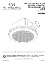
SPECIFICATIONS
Model No.
Air CFM
V
Hz
Duct Diameter
Noise (Sones)
DSQR70BNOR
70 CFM
120
60
4 in. (10 cm)
1.5
DIMENSIONS
Ceiling
Opening – D
Ceiling
Opening – W x L
Housing
Dimension – W x L
Housing
Dimension - D
Grille
Dimension
6
1
/
5
in.
( 15.8
cm)
in. x 8
1
/
2
in.
(22
cm x 21.5
cm)
8
3
/
10
in. x 8
in.
(21
cmx 20.5
cm)
5
4
/
5
in.
(14.8
cm)
12
in
.
(
30.5cm
x
cm)
WIRING DIAGRAM
For Customer Support please email [email protected], or call (888)930-8528. Please provide the bath fan model number found
on the front of this manual when contacting Customer Support.
30.5
12
in
.
x
8 /
5
3

Page 5 Model: DSQR70BNOR
For Customer Support please email [email protected], or call (888)930-8528. Please provide the bath fan model number found
on the front of this manual when contacting Customer Support.
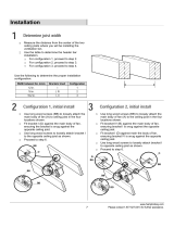
FAN HOUSING INSTALLATION (DIRECT JOIST MOUNTING OR SUSPENSION BRACKET JOIST MOUNTING)
Check the area above installation location to be sure that:
a. Ductwork can be run and there is sufficient area for proper ventilation;
b. Wiring can be run to the planned location (wires from the power supply to the unit should be 12-18
AWG);
c. There will be accessible to ductwork and wiring for inspection and future maintenance;
d. No wiring or other obstructions will interfere with installation.
For installation in existing construction:
Installing the fan housing in an existing building requires access (attic or crawl space) in the planned
installation location above the existing ductwork and wiring.
Inspect existing ductwork and wiring before proceeding with installation.
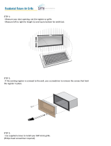
Step 1: Turn off power source. Review all safety
precautions.
Step 2: Remove the existing fan.
Step 3: Measure the opening to ensure it is large
enough to accommodate the new fan housing.
(8-3/5
in. x 8-1/2
in.
)
Step 4: If this fan is not replacing an old fan, be sure
cut a 8-
in. x 8-
in. opening for the bath
fan housing.
Step 5: Place the bath fan housing next to a ceiling
joist or wall stud. The fan housing should be level and
perpendicular to the joist or stud. Allow for thickness
of the ceiling board used in your application.
Do NOT flush mount to joist. Bottom of fan housing
should be flush with ceiling board.
Step 6: Mount fan housing to the joist or stud using
long wood screws (M4*30) where indicated by arrows
outside fan housing.
3/5
1/2
8-
in.
3/5
8
-
in.
1/2

Model: DSQR70BNOR Page 6
For Customer Support please email [email protected], or call (888)930-8528. Please provide the bath fan model number found
on the front of this manual when contacting Customer Support.
Step 7: Disconnect the power supply before
proceeding with Step 7. Run 120V 60Hz house wiring
(with ground) from wall switches to fan location.
Remove junction box cover and, using wire nuts,
connect house wires to unit wires. Refer to Wiring
Diagram on page 4.
Note: 12AWG is the minimum conductor to be used
for branch-circuit wiring.
CAUTION: If you electrical wires do not match the
colors listed, you must determine what each house
wire represents before connecting. You may need to
consult an electrical contractor to determine safely.
Wire Nuts instructions:
WARNING: Wiring must comply with all applicable
electrical codes. Turn OFF power before removing or
installing connectors. COPPER TO COPPER ONLY. Do
not use aluminum wire.
CAUTION: Accessory part (Wire nuts) should meet
installation instructions below.
NOTE: The connector in reusable on solid wires of the
same wire gage or smaller. Do not reuse the nut on
stranded wires.
Strip wires 3/8”-1/2”
Grip the wire firmly and push the stripped end of
the wire into the open port of the nut. Use only
one conductor per port.
Verify the stripped end of the wires is fully inserted
to the back of the nut.
NOTE: Important wire information. Maximum
temperature rating 105℃(221℉).600 volts maximum
for building wire and 1000 volts maximum for
building wire and 1000 volts maximum in signs and
lighting fixtures. The acceptable wire range includes:
solid 12-18 AWG.
Green wires are ground wires. House ground may
be green or bare.
White wires are neutral. They carry power back to
the service panel.
Black wires are hot. They carry power from the
panel to the fan.
Step 8: Install a circular 4 in. duct and secure it with
duct tape or clamps.
Finish ceiling work. (Ceiling hole should be aligned
with edge of fan housing.)
Step 9: Then thread Light harness plug onto screw in
fan housing as shown.
Step 10: Connect the Light harness plug into the white

Page 9 Model: DSQR70BNOR
For Customer Support please email [email protected], or call (888)930-8528. Please provide the bath fan model number found
on the front of this manual when contacting Customer Support.
receptacle in the fan housing.
Step 11: Install two (lamp base E12) bulbs.
Step 12: Place bath fan shade onto the Light harness
plug. Secure bath fan shade to rod with finial cap and
finial nut.
Turn on electricity at breaker box after finishing
installation.

Model: DSQR70BNOR Page 8
CLEANING AND MAINTENANCE THE VENTILATION FAN
Cleaning the unit periodically is advisable since dust, molds, grease, and other dirt particles can affect the
conductivity of the air in the unit.
WARNING:
Disconnect power supply before servicing. See SAFETY INFORMATION before proceeding. Routine
maintenance should be done at least once a year.
CAUTION:
Never use solvents, thinner or harsh chemicals for cleaning the fan.
Do not allow water to enter the motor.
Do not immerse resin parts in water over 140℉.
1) Carefully unscrew finial cap and finial nut to remove from the bath fan grille.
2) Clean glass shade with a soft towel or paper towels and glass cleaner (avoid harsh detergent) in a sink.
3) Clean inside of unit with a vacuum cleaner. Do not use liquid cleaner, as the motor should not come in
contact with any liquid.
4) Dry the bath fan shade and grille with a soft towel or paper towels.
5) Put the grille back in place.
For Customer Support please email [email protected], or call (888)930-8528. Please provide the bath fan model number found
on the front of this manual when contacting Customer Support.

Page 9 Model: DSQR70BNOR
For Customer Support please email [email protected], or call (888)930-8528. Please provide the bath fan model number found
on the front of this manual when contacting Customer Support.
WARRANTY
Liftbridge Kitchen & Bath fan Model DSQR70BNOR is covered by a 3-year limited warranty. The manufacturer
warranties the bath fan motor and all other parts/components on this bath fan present at the time of shipment from the
factory to be free from defects in workmanship and material for 3 years after the date of purchase by the original
purchaser, when properly installed and under normal conditions of use. To obtain warranty service you must register
your product as directed below. This warranty does not cover products that have been abused, altered, damaged, or
misused. The manufacturer DISCLAIMS all other implied or express warranties including warranties of merchantability
and/or fitness for a particular purpose. As some states do not allow exclusions or limitations on an implied warranty, the
above exclusions and limitations may not apply. This warranty gives you specific rights, and you may have other rights
that vary from state to state.
THIS WARRANTY IS LIMITED TO REPAIR OR REPLACEMENT OF DEFECTIVE PARTS ONLY, AND ANY COSTS RELATED TO
SAME SHALL NOT EXCEED THE USER’S COST OF THE PRODUCT. MANUFACTURER ALSO RETAINS THE OPTION OF
REFUNDING PURCHASE PRICE AS FULL SETTLEMENT OF ANY WARRANTY CLAIM.
Any changes related to installation, repair, replacement, or damages related to same are excluded.
CUSTOMER SUPPORT
For Customer Support please call us at (888)930-8528, or email support@strategicretailsolutions.com. Please provide
your bath fan model number when contacting Customer Support.
PRODUCT REGISTRATION
To warranty your fan, complete registration by using either of the following methods:
Fill out the registration form on our website, at www.strategicretailsolutions.com/#productreg
or
Fill out the warranty registration below and mail it to this address:
Strategic Retail Solutions
Attn: Bath Fan Registration
PO Box 2086
Stillwater, MN 55082
LIFTBRIDGE KITCHEN & BATH FAN WARRANTY REGISTRATION
First Name:
Last Name:
Street Address:
City:
State:
Zip:
Phone:
( )
Date of Purchase:
Model Number:
DSQR70BNOR
/