Page is loading ...

Electric height adjustable desk
ASSEMBLY &
USE INSTRUCTIONS

CAUTION/INFORMATION
Make sure no obstacles are in the desk's path.
Make sure the desktop is not touching any walls.
Make sure all cords are appropriate length to
accommodate the change in height.
WARNING
PINCH POINT
keep hands and
fingers clear.
Keep children away from electric height-adjustable desks,
control units and handsets. There is a risk of injury and electric shock.
Keep all electrical components away from liquids.
Do not set or stand on the desk Frame.
Do not crawl or lie under the desk Frame.
Do not place any objects taller than 50 underneath the desk.cm
This product is designed with a duty cycle of 10% (2 min. on, 18 min. off)
In the event of a power outage or if the power cord is unplugged,
a manual reset may be necessary - see Step 12.
USE/LIABILITY
This height adjustable desk has electric motors and is designed for use in dry work areas only. The
desk height is adjustable so that it can be positioned at the most ergonomically suitable height.
Any other use is at user's risk.
Under no circumstances does the manufacturer accept warranty claims or liability claims for damages
caused from improper use or handling of the desk frame.
IMPORTANT:
Please read this manual carefully.
If this desk is sold ,please provide this manual to the buyer.
Do not open any of the components - the Legs, control Box, or handset.
There is a danger of electric shock.
Page1

PARTS
TOOLS REQUIRED
COMPONENTS
HARDWARE
4MM Allen Wrench
(included)
Phillips Head Screwdriver
and/or Power Drill
Tape measure
Page2
Foot with
Glides
Crossbar End
Center Rail
Side Bracket
Legs
x3
x3
x4
x4
x3
Control Box
Programmable
Handset
Power cord
Cables:60cm
x1
x1
x3
x1
Machine Screws:
M6x12
x40
Cable Clips
Machine Screws:
M6x10
x16
x10
Wood Screws:
ST M5x16
x17

Part
1Crossbar End
2Leg
3Foot
4Crossbar Center Rail
5Side Bracket
6Control Box
7Programmable Handset
8Power Cord
9Cables
10
11Machine Screws:M6x12
12Machine Screws:M6x10
13Wood Screws:ST M5x16
14Cable Clips
Foot Glides
4
3
3
4
3
1
1
1
3
6
40
16
17
10
Page3
PARTS
QTY
6
8
9
7
13
14
11
10
3
2
5
1
4
12
11
11

ASSEMBLY INSTRUCTIONS
Page4
Lay out all components and hardware to ensure that you have all components and hardware listed on the
parts page.
Fully separate the Crossbar Ends (Part #1). You will find the Crossbar Center Rails (Part #4) inside.
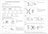
STEP1
Place one of the Legs (Part #2) into the Crossbar End (Part #1)
Line up the holes on each Leg (Part #2) with the holes on each
Crossbar End (Part #1)
Using the supplied Allen Wrench, insert four (4) M6x12 Machine
Screws (Part #11) through the holes in each Crossbar End (Part #1) going
into the Leg (Part #2) and rotate each screw just a few turns.
You will need to dip the assembly over to gain access to all four (4) M6x12
Machine Screws (Part #11).
STEP2

ASSEMBLY INSTRUCTIONS
Page5
STEP3
Position one of the Crossbar Ends (Part #1) on its side.
Tighten the screws(Part #16) from the top.
If you drop a screw inside the Crossbar End (Part #1), simply tilt
to retrieve the screw.
Using the Allen Wrench, rotate each screw just a few turns.
Repeat Step 4 with the other assembly.
If you are having difficulty inserting any of the
screws from Step 3 or 4, it is because some of
the installed screws are too tight.
Slide the two (2) Crossbar center Rails (Part #4)
into the two Crossbar Ends, (Part #1)
ensuring:
a) the slots Face inward
b) the slot is closer to top edge of the
Crossbar center Rail (Part #4) when
the assembly is upside down (see inset)
STEP4

ASSEMBLY INSTRUCTIONS
Page6
STEP4
STEP5
Lock the position of the Crossbar center Rails (Part #4)
using eight (8) M6x10 Machine Screws (Part #12).
Remember,maximum width is 180cm.
Using the M6*10 Machine Screw(part 12) to fix the 3rd central frame.

ASSEMBLY INSTRUCTIONS
Page7
STEP6
STEP7
For each leg, attach a foot (Part #3) with
four (4) M6x12 Machine Screws (Part #11)
and tighten screws in a cross pattern.
Lock the position of the Crossbar center Rails (Part #4)
using eight (8) M6x10 Machine Screws (Part #12).
Remember,maximum width is 180cm.

ASSEMBLY INSTRUCTIONS
TROUBLESHOOTING
TECHNICAL SPECIFICATIONS
Plug the Power Cord into a 240v outlet.
Make sure no obstacles are in the desk's path.
Make sure the desktop is not touching any walls.
Make sure all cords are appropriate length to accommodate the change in height
IMPORTANT: You must RESET the desk prior to use.
Height Range
Base width
Travel Speed
Weight capacity
Duty Cycle
60CM-125CM(without desktop)
110CM-180CM
38 per second(no load)
1 0kg8
10%. Max. 2 mins on, 18 mins off
Soft start/stop
Adjustable leveling studs
4 Memory presets
STEP8
Page8
IF your desk is not functioning properly it may need to be reset. Unplug the power cord for 20 seconds.
Plug the power cord back in and follow the RESET procedure outlined in step 8.
IF the LED readout displays “Er8" or "Er9" or "Er00"confirm that all wired connections are secure
(legs to cables, cables to control box). Then perform the reset procedure outlined in step 8.
IF the error message persists after the reset procedure, contact your seller.
IF the height between the legs exceeds 4cm, perform the reset procedure outlined in step 8.
IF the handset displays “HOT” , let the base cool down for 20 minutes.
RESET PROCEDURE: Push and hold the DOWN button on the Programmable Handset (Part #7) the
LED reads “RST”
until the desk reaches its lowest height, slightly rises and stops. Release the DOWN button.
Your desk is now ready to use.
To program up to four presets: Use the up/down buttons to find a desired height, then press "S"(or “M”)
followed by a number 1 - 4.
CAUTION: Once a preset button is pushed, the desk will move to the programmed height .

USE INSTRUCTIONS
Up & Down Movement:
Press the UP arrow continuously, the legs will move up
Press the DOWN arrow continuously, the legs will move down
Release arrows to stop movement.
Memory Preset Positions:
Use the UP and DOWN arrows to set table at a desired height.
Press the POSITION SETTING BUTTON (S) followed by one of the 4 PRESET POSITION
BUTTONS(1 2 3 4) buttons. The memory position is set.
There are up to 4 presets available. To return to a memory preset press the desired number.
Warning:
It is recommended that the legs not be moved up and down continuously for more than 2
minutes within a 20 minute interval or exceed the lift capacity.
To avoid over loading the transformer an overload protection program is built into the system.
If the unit stops working let it cool off before trying to raise or lower it again.
If the unit overloads the LED display will display "HOT".
Reset:
Press the DOWN button and lower the desk to its lowest setting..
Press the DOWN Button again for ~ 5 seconds until the LED reads “RST”
Press the DOWN button & hold it while the legs move up & down to level and stop.
Release the DOWN button as the reset is now complete and your table is ready to use.
Error Code Key:
E02 –unbalanced, keep the desk moving will auto matically adjust it to balance state.
E04 –overload,move something off the desk to reduce the loading weight.
E05 – resistance to return.
R5T - means “reset” cycle in progress.
Er8 – miscommunication between control box and legs plugged into port 1.
Er9– miscommunication between control box and legs plugged into port 2.
HOT –desk has reached its duty cycle limit – let desk base cool for 20 minutes.
Page9
/