Page is loading ...

Crestron Green Light™
DIN-AP2
DIN Rail Control Processor
Operations & Installation Guide

This document was prepared and written by the Technical Documentation department at:
Crestron Electronics, Inc.
15 Volvo Drive
Rockleigh, NJ 07647
1-888-CRESTRON
All brand names, product names and trademarks are the property of their respective owners.
©2008 Crestron Electronics, Inc.

Crestron DIN-AP2 DIN Rail Control Processor
Contents
Crestron Green Light™ DIN Rail Control Processor: DIN-AP2 1
Introduction ...............................................................................................................................1
Features and Functions................................................................................................1
Applications.................................................................................................................4
Specifications ..............................................................................................................5
Physical Description....................................................................................................7
Industry Compliance .................................................................................................12
Setup........................................................................................................................................13
Network Wiring.........................................................................................................13
Installation.................................................................................................................13
Hardware Hookup .....................................................................................................15
Programming Software............................................................................................................19
Earliest Version Software Requirements for the PC .................................................19
Programming with Crestron SystemBuilder..............................................................20
Programming with D3 Pro.........................................................................................20
Programming with SIMPL Windows........................................................................20
Uploading and Upgrading........................................................................................................22
Establishing Communication.....................................................................................22
Programs and Firmware ............................................................................................24
Program Checks ........................................................................................................24
Problem Solving......................................................................................................................25
Troubleshooting.........................................................................................................25
Check Network Wiring..............................................................................................29
Reference Documents................................................................................................31
Further Inquiries........................................................................................................31
Future Updates ..........................................................................................................31
Software License Agreement...................................................................................................32
Return and Warranty Policies..................................................................................................34
Merchandise Returns / Repair Service ......................................................................34
CRESTRON Limited Warranty.................................................................................34
Operations & Installation Guide – DOC. 6662A Contents • i


Crestron DIN-AP2 DIN Rail Control Processor
Crestron Green Light™ DIN Rail
Control Processor: DIN-AP2
Introduction
The DIN-AP2 is a 2-Series control processor designed for small to
medium-sized lighting and automation applications. DIN rail mounting
enables modular installation alongside Crestron
®
DIN Rail lighting and
automation control modules and other third-party DIN rail mountable
devices.
Features and Functions
• 2-Series control engine
• MMC memory expansion card slot
• Cresnet port - master/slave selectable
• 10/100 Ethernet | SSL encryption
• e-Control
®
2, SNMP, & RoomView
®
support
• Two bidirectional RS-232 COM ports
• Four IR/serial ports
• Eight Versiport I/O ports
• Four low-voltage relay ports
• Configurable using D3 Pro™ or Crestron SystemBuilder™
software
• 9M wide DIN rail mounting
• Requires external power supply
Operations & Installation Guide – DOC. 6662A DIN Rail Control Processor: DIN-AP2 • 1

DIN Rail Control Processor Crestron DIN-AP2
2-Series Processor
Built upon Crestron’s reliable 2-Series control engine, the DIN-AP2 is
extensively programmable using Crestron’s suite of powerful
development software and vast database of drivers and software modules.
The DIN-AP2 works seamlessly with Crestron’s entire line of lighting
dimmers and shade controls, keypads and touchpanels, thermostats,
wireless gateways, and expansion modules.
DIN Rail Installation
The DIN-AP2 is designed to snap onto a standard DIN rail for
installation in a wall mount enclosure or mounted on a wall panel. Wiring
connections are made using detachable screw terminals positioned along
the top and bottom, clearly accessible from the front for easy installation
and servicing. All setup controls and connections are positioned on the
center front panel. When installed in an enclosure utilizing 45 mm
cutouts, the DIN-AP2’s front panel stays accessible while all other
connections are concealed.
System Integration
The DIN-AP2 provides for the integration of non-Crestron devices and
subsystems through a host of control interfaces. Four isolated relays and
eight Versiport I/O ports are built in to accommodate all kinds of sensors,
contactors, door strikes, and other low-voltage controls. Two
bidirectional RS-232 COM ports and four IR/serial ports allow for the
integration of everything from simple shade controllers to advanced
security systems. Additional interfaces and controllers can be added
easily using Crestron’s DIN Rail series lighting and automation modules.
Cresnet
®
Cresnet is the communications backbone for Crestron lighting modules,
wall box dimmers, shade controllers, thermostats, keypads, touchpanels,
and many other devices. This flexible 4-wire bus streamlines the wiring
of a complete Crestron system. The DIN-AP2 includes a pair of Cresnet
master ports (paralleled) capable of supporting approximately 20 typical
devices. Larger systems with more than 20 devices can be handled by
adding the DIN-HUB Cresnet Distribution Hub. Connectivity for
multiple homeruns can be facilitated using one or more DIN-BLOCK
Cresnet Distribution Blocks. Additionally, at least one DIN-PWS50
2 • DIN Rail Control Processor: DIN-AP2 Operations & Installation Guide – DOC. 6662A

Crestron DIN-AP2 DIN Rail Control Processor
Cresnet Power Supply is required to power the DIN-AP2 and any
connected Cresnet devices.
Ethernet and e-Control
®
2
Built-in 10/100 Ethernet facilitates secure high-speed network
connectivity, enabling extensive capabilities for remote system
maintenance and control, and providing an interface to other Crestron
control systems. Native features include a built-in email client to report
system troubles and other functions to the owner or service company via
instant e-mail notification. An onboard Web server provides the
foundation for Crestron’s exclusive e-Control2 Xpanel technology,
providing secure IP-based remote control.
RoomView
®
and SNMP
For large facilities utilizing multiple DIN-AP2’s and other control
systems, Crestron's exclusive RoomView Help Desk software delivers a
comprehensive solution for remote monitoring and asset management.
Also, built-in SNMP support enables similar capability using third-party
network management software, allowing full control and monitoring
from the IT Help Desk or NOC in a format that is familiar to IT
personnel.
Memory Expansion
A memory card slot allows for easy expansion of the DIN-AP2's internal
memory using a MMC (Multimedia Memory Cards)-compatible memory
card up to 2 GB.
D3 Pro™ & Crestron SystemBuilder™ Software
Crestron D3 Pro and SystemBuilder software eliminates the need for
custom programming, providing a complete design, development, and
documentation solution for the lighting professional.
Operations & Installation Guide – DOC. 6662A DIN Rail Control Processor: DIN-AP2 • 3

DIN Rail Control Processor Crestron DIN-AP2
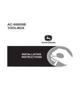
Applications
The following diagram shows a DIN-AP2 in a typical application.
DIN-AP2 in a Typical Application
4 • DIN Rail Control Processor: DIN-AP2 Operations & Installation Guide – DOC. 6662A

Crestron DIN-AP2 DIN Rail Control Processor
Specifications
Specifications for the DIN-AP2 are listed in the following table.
DIN-AP2 Specifications
SPECIFICATION DETAILS
CPU 32-bit Freescale ColdFire
®
Microprocessor
Memory
SDRAM
NVRAM
Flash
Removable Storage
32 MB
256 KB
8 MB
Up to 2 GB using MMC (Multimedia
Memory Cards) compatible card
(not included)
Operating System Real-time, preemptive multi-
threaded/multitasking kernel;
FAT32 file system with long names;
supports SIMPL™ Windows
®
and
SIMPL+
®
Ethernet 10/100BaseT, auto-negotiating,
full/half duplex, static IP or
DHCP/DNS, SSL, TCP/IP, UDP/IP,
CIP, SMTP, SNMP, built-in Web
server and e-mail client; supports
Crestron e-Control
®
2 XPanel and
RoomView
®
applications
Power Requirements
Cresnet Power Usage
8.0 Watts
(0.33 Amps @ 24 Volts DC)
(Power supply sold separately)
Environmental
Temperature
Humidity
Heat Dissipation
0° to 40°C (32° to 104°F)
10% to 90% RH (non-condensing)
26 BTU/Hr
(Continued on following page)
Operations & Installation Guide – DOC. 6662A DIN Rail Control Processor: DIN-AP2 • 5

DIN Rail Control Processor Crestron DIN-AP2
DIN-AP2 Specifications (Continued)
SPECIFICATION DETAILS
Enclosure Light gray polycarbonate housing
with polycarbonate label overlay,
UL94 V-0 rated, 35 mm DIN EN
60715 rail mount, DIN 43880 form
factor for enclosures with 45 mm
front panel cutout, occupies 9 DIN
module spaces (162 mm).
Dimensions
Height
Width
Depth
94.2 mm (3.71 in)
159 mm (6.26 in)
58 mm (2.28 in)
Weight 303 g (11 oz)
Available Accessories
DIN-BLOCK
DIN-HUB
DIN-PWS50
DIN Rail Series
IRP2
DIN Rail Cresnet Distribution Block
DIN Rail Cresnet Distribution Hub
DIN Rail Power Supply
DIN Rail Lighting & Automation
Control Modules
IR Emitter Probe
6 • DIN Rail Control Processor: DIN-AP2 Operations & Installation Guide – DOC. 6662A

Crestron DIN-AP2 DIN Rail Control Processor
Physical Description
This section provides information on the connections, controls and
indicators available on your DIN-AP2.
DIN-AP2 Physical View
DIN-AP2 Overall Dimensions
90 mm
(3.54 in)
58 mm
(2.28 in)
159 mm
(6.26 in)
94.2 mm
(3.71 in)
1
5
8 10
2
4
3
6
7 9 11 13
12
Operations & Installation Guide – DOC. 6662A DIN Rail Control Processor: DIN-AP2 • 7

DIN Rail Control Processor Crestron DIN-AP2
Connectors, Controls & Indicators
# CONNECTORS
1
,
CONTROLS &
INDICATORS
DESCRIPTION
1 I/O VERSIPORTS 1-8 (1) 9-pin 3.5mm detachable
terminal block comprising (8)
digital input/output or analog
input ports (referenced to GND)
Max Wire Size: 1.5 mm
2
(16 AWG)
Digital Input:
Rated for 0-24 Volts DC
Input Impedance 20k ohms
Logic Threshold: 1.25 Volts
DC
Analog Input:
Rated for 0-10 Volts DC,
protected to 24 Volts DC
maximum
Input Impedance 20k ohms
Digital Output:
250 mA sink from maximum
24 Volts DC, catch diodes
for use with “real world”
loads
Programmable 5 Volts, 2k ohms
pull-up resistor per input
2 PWR LED (1) Green LED, indicates power
supplied to unit via NET port
3 NET LED (1) Yellow LED, indicates
Cresnet bus activity
(Continued on following page)
8 • DIN Rail Control Processor: DIN-AP2 Operations & Installation Guide – DOC. 6662A

Crestron DIN-AP2 DIN Rail Control Processor
Connectors, Controls & Indicators (Continued)
# CONNECTORS
1
,
CONTROLS &
INDICATORS
DESCRIPTION
4 MSG LED (1) Red LED, illuminates when
a message is present in the
message log. To view the
contents of the message log,
use Crestron Toolbox™.
5 NET
2
(2) 4-pin 3.5 mm detachable
terminal blocks, paralleled
Cresnet port and 24 Volt DC
power input.
Max Wire Size: 1.5 mm
2
(16 AWG)
Master/Slave selectable
24: Power (24 VDC)
Y: Data
Z: Data
G: Ground
6 HW-R (1) Recessed button reboots
the control system.
7 SW-R (1) Recessed button restarts
the control system program.
8 MEMORY (1) MMC compatible card slot
Accepts Multimedia Memory
Cards (MMC) up to 2 GB
(Continued on following page)
Operations & Installation Guide – DOC. 6662A DIN Rail Control Processor: DIN-AP2 • 9

DIN Rail Control Processor Crestron DIN-AP2
Connectors, Controls & Indicators (Continued)
# CONNECTORS
1
,
CONTROLS &
INDICATORS
DESCRIPTION
9 COM1 & COM 2
(2) 5-pin 3.5 mm detachable
terminal blocks, bidirectional
comprising (2) RS-232 ports
Max Wire Size: 1.5 mm
2
(16 AWG)
Up to 115.2k baud
Hardware and software
handshaking support
GND: Ground
TX: Transmit data
RX: Receive data
RTS: Request to send
CTS: Clear to send
10 RELAYS
(1) 8-pin 3.5 mm detachable
terminal block comprising (4)
normally open, isolated relays
Max Wire Size: 1.5 mm
2
(16 AWG)
Rated 1 Amp, 30 Volts AC/DC
MOV arc suppression across
contacts
(Continued on following page)
10 • DIN Rail Control Processor: DIN-AP2 Operations & Installation Guide – DOC. 6662A

Crestron DIN-AP2 DIN Rail Control Processor
Connectors, Controls & Indicators (Continued)
# CONNECTORS
1
,
CONTROLS &
INDICATORS
DESCRIPTION
11 LAN
GREEN
LED
YELLOW
LED
PIN 8
PIN 1
(1) 8-wire RJ-45 with 2 LED
indicators
10/100BaseT Ethernet port
Green LED indicates link status
Yellow LED indicates Ethernet
activity
PIN SIGNAL PIN SIGNAL
1 TX + 5 N/C
2 TX - 6 RC -
3 RC+ 7 N/C
4 N/C 8 N/C
12 COMPUTER
Pin 1 Pin 2
Pin 4 Pin 3
(1) USB Type B female USB 1.1
computer console port
(2-meter cable included).
PIN SIGNAL PIN SIGNAL
1 +5 VDC 3 Data +
2 Data - 4 Ground
13 IR/SERIAL (1) 8-pin 3.5 mm detachable
terminal block; comprising (4)
IR/Serial output ports.
Max Wire Size: 1.5 mm
2
(16 AWG)
IR output up to 1.2 MHz
1-way serial TTL/RS-232
(0-5 Volts) up to 115.2k baud
Individual signal generator per
port, allowing simultaneous
firing of all ports
1. Interface connectors for NET, IR/SERIAL, COM 1, COM 2, I/O and RELAYS
ports are provided with the unit.
2. The DIN-AP2 can only be powered via the NET port. Be sure to use a Crestron
approved power supply as another may cause damage.
Operations & Installation Guide – DOC. 6662A DIN Rail Control Processor: DIN-AP2 • 11

DIN Rail Control Processor Crestron DIN-AP2
Industry Compliance
This unit has been manufactured to comply with UL’s Standards for
Safety in Canada and the United States. Formal approval is pending.
As of the date of manufacture, the DIN-AP2 has been tested and found to
comply with specifications for CE marking and standards per EMC and
Radiocommunications Compliance Labelling.
NOTE: This device complies with part 15 of the FCC rules. Operation is
subject to the following two conditions: (1) this device may not cause
harmful interference and (2) this device must accept any interference
received, including interference that may cause undesired operation.
This equipment has been tested and found to comply with the limits for a
Class B digital device, pursuant to part 15 of the FCC Rules. These limits
are designed to provide reasonable protection against harmful
interference in a residential installation. This equipment generates, uses
and can radiate radio frequency energy and if not installed and used in
accordance with the instructions, may cause harmful interference to radio
communications. However, there is no guarantee that interference will
not occur in a particular installation. If this equipment does cause harmful
interference to radio or television reception, which can be determined by
turning the equipment off and on, the user is encouraged to try to correct
the interference by one or more of the following measures:
Reorient or relocate the receiving antenna.
Increase the separation between the equipment and receiver.
Connect the equipment into an outlet on a circuit different from
that to which the receiver is connected.
Consult the dealer or an experienced radio/TV technician for help.
12 • DIN Rail Control Processor: DIN-AP2 Operations & Installation Guide – DOC. 6662A

Crestron DIN-AP2 DIN Rail Control Processor
Setup
Network Wiring
When wiring the Cresnet and Ethernet network, consider the following:
• Use Crestron Certified Wire.
NOTE: Cresnet-HP wire cannot be used.
• Use Crestron power supplies for Crestron equipment.
• Provide sufficient power to the system.
CAUTION: Insufficient power can lead to unpredictable results
or damage to the equipment. Please use the Crestron Power
Calculator to help calculate how much power is needed for the
system (
www.crestron.com/calculators).
Cresnet
For networks with 20 or more devices, use a Cresnet Hub/Repeater
(DIN-HUB) to maintain signal quality.
For more details, refer to “
Check Network Wiring” on page 29.
Ethernet
The DIN-AP2 can also use high-speed Ethernet for communications with
other IP-based devices.
For information on connecting Ethernet devices in a Crestron system,
refer to the latest version of the Crestron e-Control
®
Reference Guide
(Doc. 6052), which is available for download from the Crestron website
(
www.crestron.com/manuals).
Installation
The DIN-AP2 must be installed by a licensed electrician, in accordance
with all national and local codes.
CAUTION: This equipment is for indoor use only. Mount in a well
ventilated area. The ambient temperature must be 0º to 40º C
(32º to 104º F). The relative humidity must be 10% – 90%
(non-condensing).
Operations & Installation Guide – DOC. 6662A DIN Rail Control Processor: DIN-AP2 • 13

DIN Rail Control Processor Crestron DIN-AP2
The DIN-AP2 is designed for installation on a DIN rail. Refer to the
following diagram when installing.
Installing the DIN-AP2
DIN RAIL RELEASE
DIN-AP2
TOP
DIN RAIL
(NOT SUPPLIED)
1. Place the top of the DIN-AP2’s rail mount over the top of the DIN
rail.
2. Tilt the bottom of the DIN-AP2 toward the DIN rail until it snaps
into place.
NOTE: When mounting DIN rail products, it may be necessary to
use a flat-head screw driver to pull the DIN rail release tab while
snapping the device onto the DIN rail.
To remove the DIN-AP2 from the DIN rail, use a small, flat object (i.e. a
flat-head screwdriver) to pull the DIN rail release and tilt the bottom of
the DIN-AP2 away from the DIN rail.
NOTE: Certain third party DIN cabinets provide space for an
informational label between each DIN rail row. Crestron’s Engraver
software (version 4.0 or later) can generate appropriate labels for all
Crestron DIN rail products.
14 • DIN Rail Control Processor: DIN-AP2 Operations & Installation Guide – DOC. 6662A

Crestron DIN-AP2 DIN Rail Control Processor
Hardware Hookup
Connect the
Device
Make the necessary connections as called out in the illustration that
follows this paragraph. Refer to “
Network Wiring” on page 13 before
attaching the 4-position terminal block connector. Apply power after all
connections have been made.
WARNING: Prior to connecting the device, turn off power at the circuit
breaker. Failure to do so may result in serious personal injury or damage
to the device. Restore power after all connections have been made.
CAUTION: Connecting this device to the wrong type of load, or short-
circuiting the load can cause severe product damage. Each load should be
tested to identify a short circuit condition prior to wiring the load to the
module.
NOTE: Install in accordance with all local and national electric codes.
NOTE: Use copper wire only.
When making connections to the DIN-AP2, use a Crestron power supply.
Operations & Installation Guide – DOC. 6662A DIN Rail Control Processor: DIN-AP2 • 15

DIN Rail Control Processor Crestron DIN-AP2
Hardware Connections for the DIN-AP2
NET:
POWER FROM
DIN-PWS50 OR OTHER
CRESNET POWER SUPPLY.
PASS-THROUGH TO
OTHER CRESNET DEVICES
COM 1 & COM 2:
BI-DIRECTIONAL RS-232
WITH HARDWARE &
SOFTWARE HANDSHAKING
LAN:
10/100 BASE-T
ETHERNET TO LAN
IR/SERIAL:
TO IR-CONTROLLED DEVICES
or ONE-WAY SERIAL
CONTROLLED DEVICES
RELAYS:
TO CONTROLLABLE
DEVICES
MEMORY:
FOR OPTIONAL MMC
COMPATIBLE
MEMORY CARD
I/O:
TO CONTROLLABLE
DEVICES &
FROM DEVICE OUTPUTS
COMPUTER:
TO USB PORT ON PC
NOTE: Ensure the unit is properly grounded.
Power can be supplied from a DIN-PWS50 DIN Rail Power Supply or
other Cresnet power supply. For more information, refer to the latest
version of the DIN-PWS50 Operations & Installation Guide (Doc. 6667),
which is available for download from the Crestron website.
NOTE: The DIN-AP2 can only be powered by the 4-position terminal
block connector labeled NET.
16 • DIN Rail Control Processor: DIN-AP2 Operations & Installation Guide – DOC. 6662A
/