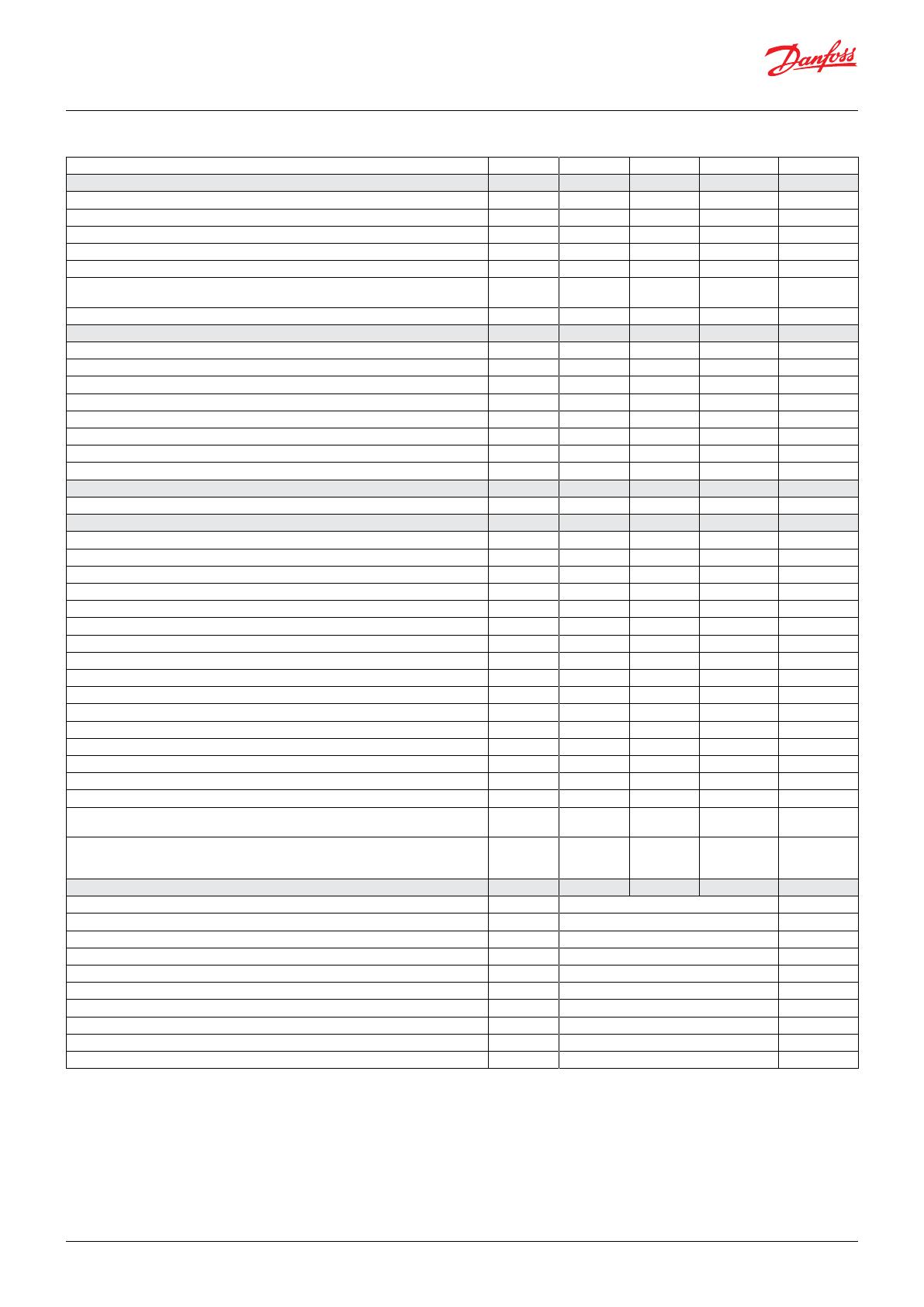
Danfoss CO2 User guide

Type
User guide

Danfoss CO2 is an innovative tool that brings efficiency and precision to CO2 refrigeration systems. Here are some highlights of its capabilities:

  • Streamlined Control: Danfoss CO2 offers centralized control of the entire refrigeration system, allowing for efficient coordination of condensing units and evaporator controllers.

  • Enhanced Oil Recovery: The device coordinates oil recovery operations, ensuring optimal performance and protection of the compressor.

  • Seamless Communication: Equipped with three Modbus communication interfaces, it facilitates data exchange with System Manager, condensing unit, and evaporator controllers.

CO2 Module controller
Universal Gateway
User Guide
danfoss.com
Module controller .................................................................................................................................3
System Overview ..................................................................................................................................................................... 3
Installation .............................................................................................................................................4
Electric Installation ................................................................................................................................................................. 4
Mechanical Installation ......................................................................................................................................................... 6
Technical data ........................................................................................................................................8
Dimensions ............................................................................................................................................8
Spare parts .............................................................................................................................................8
Operation ..............................................................................................................................................9
Survey of functions .............................................................................................................................10
Fault message ........................................................................................................................................................................12
Menu survey ............................................................................................................................................................................13
Contents
Functions
Control of connected condensing unit (CDU).
Coordination of oil recovery.
Communication with a Danfoss System Manager.
Condensing unit
The connected condensing unit is allowed to start when any of the evaporator controllers have a cooling demand.
Oil recovery
The controller coordinates oil recovery operation between the condensing unit and the evaporator controllers. During oil recovery the
expansion valves are opened and the speed of the compressor is increased.
Data communication
The controller is delivered with three interfaces for Modbus communication, each with their own function:
1. Communication with System Manager
This interface lets a Danfoss System Manager find both the connected condensing unit and all the connected evaporator controllers.
2. Communication with condensing unit
3. Communication with evaporator controllers
Important
All connections to the data communication must comply with the requirements for data communication cables.
See literature: Design guide RC8AC Data communication between ADAP-KOOL® Refrigeration Controls.
Module controller
System Overview
Below is a topology over the system
System Manager
Condensing unit
AK-SM 800/800A
AK-CC55
Remote control assembly
Evaporator controllers
User interface
12VDC
Power Supply
12VDC
+12VDC
230VAC
Modbus RTU
Modbus RTU
230VAC
Modbus RTU
CO MODULE CONTROLLER
UNIVERSAL GATEWAY
INPUT 12V DC
RS485-1
GND
A -
B -
GND
A -
B -
RS485-2
GND
A -
B -
-
+
RS485-3 PWR
RJ12
Module controller
assembly
User Guide | Optyma™ iCO2
© Danfoss | Climate Solutions | 2023.01 118A5494A - BC408446085306en-000101 | 3
User Guide | Optyma™ iCO2
4 | BC408446085306en-000101 - 118A5494A © Danfoss | Climate Solutions | 2023.01
Electric Installation
Below is an illustration of the external connections that can be made in the remote control assembly.
Module Controller
UNIVERSAL GATEWAY
INPUT: 12V DC
RS485-1
PWR
RS485-2
RS485-3
-
+
RJ12
GND
A+
B-
GND
A+
B-
A+
B-
Power supply to CDU
Short-circuit proof cable
NSGAFÖU 1,8/3kV
2 x 1,5mm²
1,2m
(in PVC sleeve)
Communication to CDU
Twisted pair, shielded cable
UNITRONIC® BUS LD
1 x 2 x 0.22
1,8m
Modbus
to evaporator
controllers
Modbus
to System Manager
N L
+V -V
M25
M20
M20
M20
4 additional knock-outs
(M20) are available
Internal wires are 1,5mm²
Installation
Power supply to CDU
230V AC 1,2m cable for this is included.
Connect Module controller power supply cable to L1 (left terminal) and N (right terminal) of the condensing unit control panel - power
supply terminal block
Caution: If the cable needs to be replaced, it must either be short-circuit proof or it must be protected by a fuse on the other end.
RS485-1
Modbus interface for connection to the System Manager
RS485-2
Modbus interface for connection to the CDU.
1,8 m cable for this is included.
Connect this RS485-2 Modbus cable to terminal A and B of the condensing unit control panel - Modbus interface terminal block. Do not
connect insulated shield to ground
RS485-3
Modbus interface for connection to the evaporator controllers
3x LED Function explanation
Blue led is ON when the CDU is connected and polled operation is complete
Red led is flashing when there is a communication fault with an evaporator controller
Green led is flashing during communication with an evaporator controller
The green LED next to the 12V power supply terminals indicates "Power OK".
Electric noise
Cables for data communication must be kept separate from other electric cables:
- Use separate cable trays
- Keep a distance between cables of at least 10 cm.
User Guide | Optyma™ iCO2
© Danfoss | Climate Solutions | 2023.01 118A5494A - BC408446085306en-000101 | 5
User Guide | Optyma™ iCO2
6 | BC408446085306en-000101 - 118A5494A © Danfoss | Climate Solutions | 2023.01
Mechanical Installation
1. Installation in the backside of the unit / backside of e-panel with provided rivets or screws (3 mounting holes provided)
Procedure:
Remove CDU panel
Mount the bracket with provided screws or rivets
Fix the e-Box to the bracket (4 screws provided)
Route and connect the provided Modbus and power supply cables to the CDU control panel
Route and connect the evaporator controller Modbus cable to the Module controller
Option: Route and connect the System Manager Modbus cable to the Module controller
2. Optional installation on the frontside (only for 10HP unit, just beside the CDU control panel, holes to be drilled)
Procedure:
Remove CDU panel
Mount the bracket with provided screws or rivets
Fix the e-Box to the bracket (4 screws provided)
Route and connect the provided Modbus and power supply cables to the CDU control panel
Route and connect the evaporator controller Modbus cable to the Module controller
Option: Route and connect the System Manager Modbus cable to the Module controller
Please wire the communication cable from the top of the control bord to the left side. The cable comes along with the module
controller.
Please pass the power cable through the insulation at the bottom of the control box.
Note:
The cables should be fixed with the cable ties and should not touch the baseplate to avoid water ingress.
Module Controller wiring
Power cable
The communication cable
and the power cable should
not touch the baseplate
Module controller wiring need to be
connected to the L1 and N -Terminals
Cable tie
Communication cable
User Guide | Optyma™ iCO2
© Danfoss | Climate Solutions | 2023.01 118A5494A - BC408446085306en-000101 | 7
User Guide | Optyma™ iCO2
8 | BC408446085306en-000101 - 118A5494A © Danfoss | Climate Solutions | 2023.01
Technical data
Supply voltage 110-240 V AC. 5 VA, 50 / 60 Hz
Display LED
Electrical connection
Power supply: Max.2.5 mm²
Communication: Max 1.5 mm²
-25 – 55 °C, During operations
-40 – 70 °C, During transport
20 - 80% RH, not condensed
No shock influence
Protection IP65
Mounting Wall or with included bracket
Weight TBD
Included in the package
1 x Remote control assembly
1 x Mounting bracket
4 x M4 screws
5 x Inox rivets
5 x Sheet metal screws
Approvals
EC Low Voltage Directive (2014/35/EU)
- EN 60335-1
EMC (2014/30/EU)
- EN 61000-6-2 and 6-3
Dimensions
Spare parts
182 90
180
Units in mm
Parts Name Parts No
Danfoss Requirements
Packing Style Remarks
Gross
weight Unit Dimension (mm)
Kg Length Width Height
CO MODULE CONTROLLER UNIVERSAL GATEWAY
MODULE CONTROLLER 118U5498 TBD 182 90 180 Carton box
Operation
Display
The values will be shown with three digits.
When you want to change a setting, the upper and the lower button will give you a higher or lower value depending on the button you are pushing. But before you
change the value, you must have access to the menu. You obtain this by pushing the upper button for a couple of seconds - you will then enter the column with
parameter codes. Find the parameter code you want to change and push the middle buttons until value for the parameter is shown. When you have changed the
value, save the new value by once more pushing the middle button. (If not operated for 10 seconds, the display will change back to showing the suction pressure
in temperature).
Examples:
Set menu
1. Push the upper button until parameter code r01 is shown
2. Push the upper or the lower button and find that parameter you want to change
3. Push the middle button until the parameter value is shown
4. Push the upper or the lower button and select the new value
5. Push the middle button again to freeze the value.
See alarm code
A short press of the upper button
If there are several alarm codes they are found in a rolling stack.
Push the uppermost or lowermost button to scan the rolling stack.
Set point
1. Push upper button until display shows parameter menu code r01
2. Select and change par. r28 to 1, which defines the MMILDS UI as the reference set device
3. Select and change par. r01 to the required lower pressure setpoint target in bar(g)
4. Select and change par. r02 to the required upper pressure setpoint target in bar(g)
Remark: The arithmetic middle of r01 and r02 is the target suction pressure.
Get a good start
With the following procedure you can start regulation as soon as possible.
1. Connect the modbus communication to CDU.
2. Connect the modbus communication to evaporator controllers.
3. Configure the address in each evaporator controller.
4. Perform a network scan in the module controller (n01).
5. Verify that all evap. controllers have been found (Io01-Io08).
6. Open parameter r12 and start the regulation.
7. For connection to a Danfoss System Manager
- Connect the modbus communication
- Set the address with parameter o03
- Perform a scan in the System Manager.
Active alarm (red triangle)
Scan for Evap. controller is in progress (yellow clock)
User Guide | Optyma™ iCO2
© Danfoss | Climate Solutions | 2023.01 118A5494A - BC408446085306en-000101 | 9
User Guide | Optyma™ iCO2
10 | BC408446085306en-000101 - 118A5494A © Danfoss | Climate Solutions | 2023.01
Function Parameter Remarks
Normal display
The display shows the suction pressure in temperature.
Regulation
Min. Pressure
The lower setpoint for suction pressure. See instructions for CDU. r01
Max. Pressure
The upper setpoint for suction pressure. See instructions for CDU. r02
Demand Operation
Limits the compressor speed of the CDU. See instructions for CDU. r03
Silent Mode
Enable/disable silent mode.
Operating noise is suppressed by limiting the speed of the outdoor fan and compressor.
r04
Snow Protection
Enable/disable snow protection functionality.
To prevent snow from building up on the outdoor fan during winter shutdown, the outdoor fan is operated
at regular intervals to blow off the snow.
r05
Main Switch
Start/stop the CDU r12
Reference source
The CDU can either use a reference that is configured with rotary switches in the CDU, or it can use the
reference as defined by parameter r01 and r02. This parameter configures which reference to use.
r28
For Danfoss Only
SH Guard ALC
Cut-out limit for ALC control (oil recovery) r20
SH Start ALC
Cut-in limit for ALC control (oil recovery) r21
Oil ALC setpoint LBP
(AK-CC55 parameter P87,P86) r22
SH Close
(AK-CC55 parameter ---) r23
SH Setpoint
(AK-CC55 parameter n10, n09) r24
EEV force low OD after oil recovery
(AK-CC55 AFidentForce = 1.0) r25
Oil ALC setpoint MBP
(AK-CC55 parameter P87,P86) r26
Oil ALC setpoint HBP
(AK-CC55 parameter P87,P86) r27
Miscellaneous
If the controller is built into a network with data communication, it must have an address, and the system
unit of the data communication must then know this address.
The address is set between 0 and 240, depending on the system unit and the selected data communication. o03
Evaporator controller addressing
Node 1 Address
Address of the first evaporator controller
Will only be shown if a controller has been found during scan.
Io01
Node 2 Address
See parameter Io01 Io02
Node 3 Address
See parameter Io01 Io03
Node 4 Address
See parameter Io01 Io04
Node 5 Address
See parameter Io01 Io05
Node 6 Address
See parameter Io01 Io06
Node 7 Address
See parameter Io01 Io07
Node 8 Address
See parameter Io01 Io08
Node 9 Address
See parameter Io01 Io09
Survey of functions
Function Parameter Remarks
Node 10 Address
See parameter Io01 Io10
Node 11 Address
See parameter Io01 Io11
Node 12 Address
See parameter Io01 Io12
Node 13 Address
See parameter Io01 Io13
Node 14 Address
See parameter Io01 Io14
Node 15 Address
See parameter Io01 Io15
Node 16 Address
See parameter Io01 Io16
Scan Network
Initiates a scan for evaporator controllers n01
Clear Network List
Clears the list of evaporator controllers, may be used when one or several controllers are removed, proceed
with a new network scan (n01) after this.
n02
Service
Read discharge pressure u01 Pc
Read gascooler outlet temp. U05 Sgc
Read receiver pressure U08 Prec
Read receiver pressure in temperature U09 Trec
Read discharge pressure in temperature U22 Tc
Read suction pressure U23 Po
Read suction pressure in temperature U24 To
Read discharge temperature U26 Sd
Read suction temperature U27 Ss
Read controller software version u99
Operating status (Measurement)
Push briefly (1s) the upper button. A status code will be shown on the display. The individual status codes
have the following meanings:
Ctrl. state:
CDU not operational S0 0
CDU operational S1 1
Other displays
Oil recovery Oil
No communication with CDU ---
User Guide | Optyma™ iCO2
© Danfoss | Climate Solutions | 2023.01 118A5494A - BC408446085306en-000101 | 11
User Guide | Optyma™ iCO2
12 | BC408446085306en-000101 - 118A5494A © Danfoss | Climate Solutions | 2023.01
Fault message
In an error situation an alarm symbol will flash..
If you push the top button in this situation you can see the alarm report in the display.
Here are the messages that may appear:
Code / Alarm text via data communication Description Action
E01 / CDU offline Communication lost with CDU Check CDU connection and configuration (SW1-2)
E02 / CDU communication error Bad response from CDU Check CDU configuration (SW3-4)
A17 / CDU alarm An alarm has occurred in the CDU See instructions for CDU
A01 / Evap. controller 1 offline Communication lost with evap. controller 1 Check Evap. controller controller and connection
A02 / Evap. controller 2 offline Communication lost with evap. controller 2 See A01
A03 / Evap. controller 3 offline Communication lost with evap. controller 3 See A01
A04 / Evap. controller 4 offline Communication lost with evap. controller 4 See A01
A05 / Evap. controller 5 offline Communication lost with evap. controller 5 See A01
A06 / Evap. controller 6 offline Communication lost with evap. controller 6 See A01
A07 / Evap. controller 7 offline Communication lost with evap. controller 7 See A01
A08 / Evap. controller 8 offline Communication lost with evap. controller 8 See A01
A09 / Evap. controller 9 offline Communication lost with evap. controller 9 See A01
A10 / Evap. controller 10 offline Communication lost with evap. controller 10 See A01
A11 / Evap. controller 11 offline Communication lost with evap. controller 11 See A01
A12 / Evap. controller 12 offline Communication lost with evap. controller 12 See A01
A13 / Evap. controller 13 offline Communication lost with evap. controller 13 See A01
A14 / Evap. controller 14 offline Communication lost with evap. controller 14 See A01
A15 / Evap. controller 15 offline Communication lost with evap. controller 15 See A01
A16 / Evap. controller 16 offline Communication lost with evap. controller 16 See A01
Menu survey
Function Code Min Max Factory User-Setting
Regulation
Min. Pressure r01 0 bar 126 bar CDU
Max. Pressure r02 0 bar 126 bar CDU
Demand Operation r03 0 3 0
Silent Mode r04 0 4 0
Snow Protection r05 0 (OFF) 1 (ON) 0 (OFF)
Main Switch
Start/stop the CDU r12 0 (OFF) 1 (ON) 0 (OFF)
Reference source r28 0 1 1
For Danfoss Only
SH Guard ALC r20 1.0 K 10.0 K 2.0 K
SH Start ALC r21 2.0 K 15.0 K 4.0 K
Oil ALC setpoint LBP r22 -6.0 K 6.0 K -2.0 K
SH Close r23 0.0 K 5.0 K 2.5 K
SH Setpoint r24 4.0 K 14.0 K 6.0 K
EEV force low OD after oil recovery r25 0 min 60 min 20 min
Oil ALC setpoint MBP r26 -6.0 K 6.0 K 0.0 K
Oil ALC setpoint HBP r27 -6.0 K 6.0 K 3.0 K
Miscellaneous
CDU Address o03 0 240 0
Evap. controller Addressing
Node 1 Address Io01 0 240 0
Node 2 Address Io02 0 240 0
Node 3 Address Io03 0 240 0
Node 4 Address Io04 0 240 0
Node 5 Address Io05 0 240 0
Node 6 Address Io06 0 240 0
Node 7 Address Io07 0 240 0
Node 8 Address Io08 0 240 0
Node 9 Address Io08 0 240 0
Node 10 Address Io10 0 240 0
Node 11 Address Io11 0 240 0
Node 12 Address Io12 0 240 0
Node 13 Address Io13 0 240 0
Node 14 Address Io14 0 240 0
Node 15 Address Io15 0 240 0
Node 16 Address Io16 0 240 0
Scan Network
Initiates a scan for evaporator controllers n01 0 (OFF) 1 (ON) 0 (OFF)
Clear Network List
Clears the list of evaporator controllers, may be used when one or several
controllers are removed, proceed with a new network scan (n01) after this. n02 0 (OFF) 1 (ON) 0 (OFF)
Service
Read discharge pressure u01 bar
Read gascooler outlet temp. U05 °C
Read receiver pressure U08 bar
Read receiver pressure in temperature U09 °C
Read discharge pressure in temperature U22 °C
Read suction pressure U23 bar
Read suction pressure in temperature U24 °C
Read discharge temperature U26 °C
Read suction temperature U27 °C
Read controller software version u99
User Guide | Optyma™ iCO2
© Danfoss | Climate Solutions | 2023.01 118A5494A - BC408446085306en-000101 | 13
Notes:
Notes:
16 | BC408446085306en-000101 - 118A5494A © Danfoss | Climate Solutions | 2023.01
  • Page 1 1
  • Page 2 2
  • Page 3 3
  • Page 4 4
  • Page 5 5
  • Page 6 6
  • Page 7 7
  • Page 8 8
  • Page 9 9
  • Page 10 10
  • Page 11 11
  • Page 12 12
  • Page 13 13
  • Page 14 14
  • Page 15 15
  • Page 16 16

Danfoss CO2 User guide

Type
User guide

Danfoss CO2 is an innovative tool that brings efficiency and precision to CO2 refrigeration systems. Here are some highlights of its capabilities:

  • Streamlined Control: Danfoss CO2 offers centralized control of the entire refrigeration system, allowing for efficient coordination of condensing units and evaporator controllers.

  • Enhanced Oil Recovery: The device coordinates oil recovery operations, ensuring optimal performance and protection of the compressor.

  • Seamless Communication: Equipped with three Modbus communication interfaces, it facilitates data exchange with System Manager, condensing unit, and evaporator controllers.

Ask a question and I''ll find the answer in the document

Finding information in a document is now easier with AI