Page is loading ...

(English) (CW-P15)
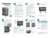
INSTALLATION, OPERATION & MAINTENANCE
Climate Wizard CW-P15 Indirect Evaporative Cool
ers
Original English Instructions
ILL2250-A
ILL3510-A
ILL2364-A
ILL2250-A


SEELEY INTERNATIONAL
- INSTALLATION MANUAL CW-P15 859740-G
|
3
TABLE OF CONTENTS
IMPORTANT SAFETY INSTRUCTIONS
For Europe 1
For Australia, New Zealand
& Other Non-European Countries 1
For Australian Bushre Prone Areas 1
Warnings 1
Employer and Employee Responsibilities 2
Risk Assessment 2
Some Points to Consider 2
Other Important Requirements 2
Maintenance Note 2
COOLER VIEWS
Top View 3
Rear View 3
Front View 3
Isometric 3
Exhaust Mount 3
Side View 3
Exploded View 4
COOLER SPECIFICATIONS 5
COOLER CONTENTS
Cooler Installation Components 6
Replacement, Optional or Spare Part Components 7
INSTALLATION
Unpacking the Cooler 9
Lifting and Moving the Cooler 9
Cooler Location 9
Drip-Tray 9
Mounting/Support 10
Vibration Isolation 10
Duct Connections 10
Inlet Air Filter Assembly 10
Electrical Supply Installation 11
Australia / Europe – 1 Phase, 220 - 240v / 50 Hz Supply
USA - 1 Or 2 Phase, 200 - 240v / 60 Hz Supply 11
Single Phase Euro/Aust Cooler Wiring Enclosure 12
Electrical Component Summary 12
High Voltage 12
Low Voltage 12
Electrical Supply Installation Wiring 12
Water Supply Installation 13
Water Supply Filtration 13
Water Hammer 13
Water Inlet Connection 13
Drain Installation 13
Control Schemes 14
Building Management System (BMS) Interface (Optional) 14
WATER MANAGEMENT SYSTEM OPERATION 14
WALL CONTROL INSTALLATION
MagIQtouch Controller 15
Control System 15
Locating the Wall Control 15
Running the Control Cable to the Wall Control 15
Mounting the Wall Control 15
MagIQcool Control Operation 16
Control Parameters 16
Wall Control Operation 16
Turning Cooler On 16
Manual Mode 16
Auto Mode 16
Delayed Start and Stop 17
Programming in Manual Mode 17
Programming in Auto Mode 17
Testing the Cooler 17
Turning Cooler On, Check Fan Operation 17
Checking Pump Operation 17
Checking Drain Operation 17
OUTLET DUCTING INSTALLATION 18
COMMISSIONING
Climate Wizard Cooling Applications 19
Top View 19
Testing the Circulation Pump 19
Testing the Drain Pump 19
Clean Up the Site 19
Show the Customer their New Cooler 19
MAINTENANCE INSTRUCTIONS
Core Removal 20
Regular / Programmed Maintenance 21
Replace Box Filter 21
Clean Chlorinator 21
Cleaning, Replacing and Checking the Water
Management Probe 22
Clean Reservoir Interior 22
Clean Drain Pump 22
Infrequent / Programmed Maintenance 23
Replace Cores 23
Breakdown Maintenance 25
Accessing Solenoid, Chlorinator, Probe or Drain Pump 26
Cable Removal 27
Replace the Chlorinator, Probe and Tornado Pump 28
Replace the Drain Pump 28
Replace the Circulation Pump 29
Replace Control Electronics 30
User Maintenance Instructions 31
OPERATING AND FAULT CODE DIAGNOSIS
Red Coloured LED 31
Tri-Coloured LED 31
MAINTENANCE SCHEDULE 33
TROUBLE SHOOTING 36
INSTALLATION CHECKLIST
Installation 37
Commissioning 37
HOW TO REGISTER YOUR PRODUCT WARRANTY
(AUSTRALIA ONLY) 38
WARRANTY TERMS AND INFORMATION
(AUSTRALIA ONLY) 39

1
|
CW-P15 Indirect Evaporative Cooler 859740-G
IMPORTANT SAFETY INSTRUCTIONS
READ AND SAVE THESE INSTRUCTIONS
FOR FUTURE REFERENCE.
FOR EUROPE
This appliance can be used by children aged
from 8 years and above and persons with
reduced physical, sensory or mental capabilities
or lack of experience and knowledge if they
have been given supervision or instruction
concerning use of the appliance in a safe way
and understand the hazards involved. Children
shall not play with the appliance. Cleaning and
user maintenance shall not be made by children
without supervision.
FOR AUSTRALIA, NEW ZEALAND & OTHER
NON-EUROPEAN COUNTRIES
This appliance is not intended for use by
persons (including children) with reduced
physical, sensory or mental capabilities, or
lack of experience and knowledge, unless they
have been given supervision or instruction
concerning use of the appliance by a person
responsible for their safety. Children should be
supervised to ensure that they do not play with
the appliance.
Means for all pole disconnection must be
incorporated in the xed wiring in accordance
with the wiring rules, adjacent to or on the
cooler cabinet. If mounting on the cooler
cabinet, take care not to puncture the water
reservoir.
The following specications for the cooler water
supply are required:
Water Connection ½” BSP (Aus/Eur), ½” NPT
(USA)
Min Water Pressure 100kPa (15psi)
Max Water Pressure 800kPa (115psi)
Max Water Flow 20 L/min (5.3 gallons/min)
Max Water Temperature 40°C (104°F)
New hose sets supplied with the appliance are
to be used and old hose-sets should not be re-
used.
If the supply cord is damaged, it must be
replaced by the manufacturer, its service agent
or similarly qualied persons in order to avoid a
hazard.
CAUTION: In order to avoid a hazard due to
inadvertent resetting of the thermal cut-out,
this appliance must not be supplied through an
external switching device, such as a timer, or
connected to a circuit that is regularly switched
on and o by the utility.
FOR AUSTRALIAN BUSHFIRE PRONE
AREAS
WARNING If this evaporative cooler is installed
in a BAL-12.5 to 29 area the evaporative cooler
dropper duct and ashings shall be adequately
sealed at the roof to prevent gaps greater than
3mm. The dropper duct and ashings shall be
non-combustible.
WARNING: This cooler is NOT APPROVED
for installation in any bushre zoned area/
property (BAL-12.5 to BAL-FZ).
WARNING - TO REDUCE THE RISK OF
FIRE, ELECTRIC SHOCK, OR INJURY TO
PERSONS, OBSERVE THE FOLLOWING:
1. Use this unit only in the manner intended
by the manufacturer. If you have questions,
contact the manufacturer.
2. Before servicing or cleaning unit, switch
power o at service panel and lock the
service disconnecting means to prevent
power from being switched on accidentally.
When the service disconnecting means
cannot be locked, securely fasten a
prominent warning device, such as a tag, to
the service panel.
3. Installation work and electrical wiring
must be done by qualied person(s) in
accordance with all applicable codes and
standards, including re-rated construction.
4. When cutting or drilling into wall or ceiling,
do not damage electrical wiring and other
hidden utilities.
5. Do not use this fan with any solid-state
speed control device.
6. Ducted fans must always be vented to the
outdoors.

SEELEY INTERNATIONAL
- INSTALLATION MANUAL CW-P15 859740-G
|
2
IMPORTANT SAFETY INSTRUCTIONS
IMPORTANT
As with any product that has moving parts or is subject to wear
and tear, it is VERY IMPORTANT that you maintain your cooler
and have it regularly serviced. It is a condition of warranty cover
for your cooler that you comply with all of the maintenance
and service requirements set out in this Manual. Compliance
with these requirements will prolong the life of your cooler.
Further, it is also a condition of warranty cover that each item
in the Maintenance Schedule in the Manual is lled out (by
signing and dating it in the places indicated) when the item is
completed.
Any failure to carry out the required maintenance and servicing,
and any failure to ll out the maintenance schedule, will void
your warranty.
MAINTENANCE NOTE
EMPLOYER AND EMPLOYEE
RESPONSIBILITIES
The installation and maintenance of evaporative coolers at
height has the potential to create Occupational Health and
Safety issues for those involved. Installers are advised to
ensure they are familiar with the relevant State and Federal
legislation, such as Acts, Regulations, approved Codes of
Practice and Australian Standards, which oer practical
guidance on these health and safety issues. Compliance
with these regulations will require appropriate work practices,
equipment, training and qualications of workers.
Seeley International provides the following information as a
guide to contractors and employees to assist in minimising risk
whilst working at height.
INSTALLER AND MAINTENANCE
CONTRACTORS - RISK ASSESSMENT
Installer and Maintenance Contractors
A risk assessment of all hazardous tasks is required under
legislation. A risk assessment is an essential element that
should be conducted before the commencement of work, to
identify and eliminate the risk of falls or to minimise these risks
by implementing control measures. There is no need for this to
be a complicated process, it just is a matter of looking at the job
to be done and considering what action(s) are necessary so the
person doing the job does not injure themselves.
This should be considered in terms of:
• What are the chances of an incident happening?
• What could the possible consequence be?
• What can you do to reduce, or better still, completely get rid of
the risk?
SOME POINTS TO CONSIDER
• What is the best and safest access to the roof and working
areas?
• If a worker is alone, who knows they are there and if they get
into diculty, how can they summon help?
• (Call someone on the ground? Mobile phone? etc.)
• What condition is the roof in? Should the trusses, underside
or surface be checked?
• Does the worker have appropriate foot wear? (Flat sole jogger
type is advisable)
• Are all power cables / extension leads safe and appropriately
rated?
• Are all ladders, tools and equipment suitable in good
condition?
• Where ladders are to be used, is there a rm, stable base for
them to stand on? Can they be tied or secured in some way
at the top? Is the top of the ladder clear of electricity supply
cables?
• Is there a roof anchor to attach a harness and lanyard to? If
so, instruction should be issued for the use of an approved
harness or only suitably trained people used.
• Are all tools and materials being used, prevented from
slipping and falling onto a person at ground level? Is the area
below the work area suitably protected to prevent persons
walking in this area?
• Does the work schedule take into account weather conditions,
allowing for work to be suspended in high winds, thunder
storms/lightning or other types of weather giving wet, slippery
surfaces?
• Is there an on-going safety check system of harnesses,
ropes, ladders and access/lifting equipment and where they
exist on roofs, anchor points before the commencement of
work?
• Is there a system which prevents employees from working
on roofs if they are unwell or under the inuence of drugs or
alcohol?
• Are there any special conditions to consider i.e. excessive
roof pitch, limited ground area, fragile roof, electrical power
lines?
OTHER IMPORTANT REQUIREMENTS
• Never force parts to t because all parts are designed to t
together easily without undue force.
• Never drill holes in the tank of the cooler.
• Check the proposed cooler location, to ensure that it is
structurally capable of supporting the weight of the cooler, or
provide an adequate alternate load bearing structure.
• Ensure the installation complies with all local and national
regulations with regards to electrical, plumbing and bushre
construction requirements.

3
|
CW-P15 Indirect Evaporative Cooler 859740-G
# Legend Qty
5 Trim Top Louver 1
6 Clamp Louver A 1
7 Clamp Louver B 1
8 Louver 1
9 Filter 1
10 Air Filter - Paper Box 6
11
Air Filter - Aluminium Box
(Premium option)
6
12 Seal Filter Frame Top 1
13 Seal Filter Frame Column 2
14 Cover Utilities Core Inlet 1
15 Pump Access Hatch 1
16 Solenoid Cover 1
17 Circulation Pump Assy 1
18 &
19
Pump Drain
Tornado Pump (50Hz Aus/Eur or
60Hz USA).
1
20 Chlorinator & Probe Enclosure 1
22 Solenoid Valve 1
23 &
24
Fitting Inlet
(BSP Aus/Eur or NPT USA)
1
25 O-ring, Inlet 1
26 Spreader Assy 3
27 Core, CW-P 3
28 Top Hatch Cover 1
29 Cover Electronics 1
30 Electronics Enclosure Assy 1
31 Aerofoil Duct, Supply Air 1
32 Aerofoil Duct, Exhaust Air 1
33 Attenuator Duct -
34 Fan 2
35 Vibration Mount 2
36 Shroud Plate & Venturi, Supply 8
37 Shroud Plate & Venturi, Exhaust 2
38 Motor Assy, P/No 865089 2
40 Motor Support Leg Assy 2
41 Elbow, Rubberized 3
42 Spreader Manifold, Rubberized 1
43 Plug, Rinse, Rubberized 1
44 Cavitation Plate, Rubberized 1
45A
Fitting, Drain Manifold,
Rubberized
1
45B
Fitting Drain Manifold Outer,
Rubberized
1
46
Pipe, Pump to Vertical,
Rubberized
1
47 Control MS1 Enclosure 1
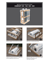
COOLER VIEWS
Side ViewFront View
Rear View
Top View
ILL2252-A
666mm
FAN C
630mm
373mm
F
TO F
AN C
AN C
930mm
FAN C
L
L
L
L
1800mm
500mm DUCT FLANGE
HOLE CENTRES
530mm SQUARE
500mm DUCT FLANGE
HOLE CENTRES
530mm SQUARE
EXHAUST
SUPPLY
1960mm
1283mm
80mm
95mm
26mm
700mm
200mm
ILL2251-A
DIMENSIONS
FROM EXHAUST MOUNT FACE:
358mm
828mm
1174mm
195mm
330mm
ILL2255-A
ILL2250-A
ILL2253-A
NOTE: THE SUPPLY MOUNT FACE
IS OFFSET BY 25MM FROM
THE EXHAUST MOUNT FACE
25mm
1440mm
1300mm
ILL2254-A
ILL2253-A
ILL2252-A
ILL2251-A
ILL2250-A
ILL2255-A
Isometric
Exhaust Mount
ILL2254-A

SEELEY INTERNATIONAL
- INSTALLATION MANUAL CW-P15 859740-G
|
4
COOLER VIEWS
# Legend Qty
5 Trim Top Louver 1
6 Clamp Louver A 1
7 Clamp Louver B 1
8 Louver 1
9 Filter 1
10 Air Filter - Paper Box 6
11
Air Filter - Aluminium Box
(Premium option)
6
12 Seal Filter Frame Top 1
13 Seal Filter Frame Column 2
14 Cover Utilities Core Inlet 1
15 Pump Access Hatch 1
16 Solenoid Cover 1
17 Circulation Pump Assy 1
18 &
19
Pump Drain
Tornado Pump (50Hz Aus/Eur or
60Hz USA).
1
20 Chlorinator & Probe Enclosure 1
22 Solenoid Valve 1
23 &
24
Fitting Inlet
(BSP Aus/Eur or NPT USA)
1
25 O-ring, Inlet 1
26 Spreader Assy 3
27 Core, CW-P 3
28 Top Hatch Cover 1
29 Cover Electronics 1
30 Electronics Enclosure Assy 1
31 Aerofoil Duct, Supply Air 1
32 Aerofoil Duct, Exhaust Air 1
33 Attenuator Duct -
34 Fan 2
35 Vibration Mount 2
36 Shroud Plate & Venturi, Supply 8
37 Shroud Plate & Venturi, Exhaust 2
38 Motor Assy, P/No 865089 2
40 Motor Support Leg Assy 2
41 Elbow, Rubberized 3
42 Spreader Manifold, Rubberized 1
43 Plug, Rinse, Rubberized 1
44 Cavitation Plate, Rubberized 1
45A
Fitting, Drain Manifold,
Rubberized
1
45B
Fitting Drain Manifold Outer,
Rubberized
1
46
Pipe, Pump to Vertical,
Rubberized
1
47 Control MS1 Enclosure 1
ILL2259-A
EXPLODED View

5
|
CW-P15 Indirect Evaporative Cooler 859740-G
COOLER SPECIFICATIONS
SPECIFICATION CW-P15
Electrical Supply - 1~ (Aus/Eur) 220-240V 50/60Hz 11 amps
Electrical Supply - 1~ (USA)
200-240V, 60Hz, 11 amps,
FLA 11A, MCA 13.3A, MOPD 15A
Water Supply
1/2” male BSP or NPT male connection.
Min. 100kPa, Max 800kPa, 20L/min
(Min. 15psi, Max. 115psi, 5.3gal/min)
Max. Operating Temp 55
0
C (131
0
F) ambient (shade)
Airow @ High Speed
1100L/s @ 140Pa
(2330cfm @ 0.56” static)
Cooling Capacity*
kW (AS2913-2000) 9.7
Btu/hr (ASHRAE 143) / kW 80700 / 23.7
Fans
Replaceable forward curve type. Glass bre reinforced polymer
with coated steel hub.
2 fans
397mm (15.6”) dia * 93mm (3.8”) wide
Motors
Diecast aluminium housing. ECM with PWM control and
overload protection.
2 motors
Input Power 900W (nominal) each
Pump - Circulation
Single phase with permanent split capacitor and thermal cut-o
protection.
230V, 50 or 60Hz.
50L/min (13.2gal/min) @ 450mBar (180”). Input
power 125W, 0.53A, 2950 RPM
Pump - Drain
SI “Tornado”, 2 pole synchronous, vertical, centrifugal, 230V 50
or 60Hz
20L/min (5.3gal/min) @ 1m (39.4”) head. Input
power 20W/ea
Chlorinator SI low voltage, catalytic chlorine generator. 1 chlorinator
Drain Connection
Recommended minimum drain pipe internal diameter is 25mm
(1”)
Rubberised tting compatible with:
1
1/2
” BSP (40mm) barbed tting
1
1/2
” NPT (40mm) barbed tting
or
40mm DWV Pipe.
(Hose clamp supplied)
Water Reservoir SI one piece, moulded polymer 47L (12.4 gal)
Heat Exchanger Core SI synthetic plate type, super ecient 3 cores
Shipping
Dimensions
2100 L * 1460 W * 1350mm H
(82.7 * 57.5 * 53.2”)
Weight 239kg (527lb)
Operating Weight Weight including reservoir water, system water, supply and
exhaust stator ducts.
335kg (739lb)
Air Filters
Type G4 standard Industry Pleated Panel washable type.
OPTIONAL: Disposable Paper type
394 * 495 * 46mm Qty 6
Nominal Size
406 * 508 * 50mm
(16 * 20 * 2”)
Frequency
(Hz)
Radiated Sound Power Level (dB re 1pw) Octave Band Centre Frequency Total Sound Power
(dB re 1pw)
63 125 250 500 1k 2k 4k 8k
CW-P15
46 54.5 62.3 65.3 70.3 65.4 57.8 50.1 77.8
*Tested in accordance with Australian Standards AS2913-2000 and ASHRAE 143 with conditions of 38.0 C (100.4°F) Dry Bulb / 21.0 C (69.8°F) Wet Bulb.

SEELEY INTERNATIONAL
- INSTALLATION MANUAL CW-P15 859740-G
|
6
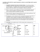
COOLER CONTENTS
COOLER INSTALLATION COMPONENTS
ITEM
PART
NO.
DESCRIPTION QTY
1A 116631 Climate Wizard Controller Kit 1
AND
1B 116808 MagIQtouch MS1 Industrial BMS kit 1
2 094694 Control Cable 20m 6 Pin (65') 1
3 879345 Warranty Card - (USA Only) 1
23 402604
Fitting Inlet with O Ring
½ inch BSP x ½ inch BSP Australia/Europe
1
24 402628
Fitting Inlet
½ inch BSP x ½ inch NPT USA
1
25 800103 O-Ring, Inlet, 25ID 1
ILL2364-A
ILL3508-A
ILL3506-A
ILL3509-A
ILL3509-A

7
|
CW-P15 Indirect Evaporative Cooler 859740-G
COOLER CONTENTS
REPLACEMENT, OPTIONAL or SPARE PART
COMPONENTS
ITEM PART NO. ILLUSTRATION DESCRIPTION
1A 094298RP MagIQtouch Controller
1B 116631
ILL3508-A
Climate Wizard Controller
1C 116792
ILL3510-A
MagIQtouch Switch Plate Controller Kit
1D 116808 MagIQtouch MS1 Industrial BMS kit
2A 094694 Control Cable 20m (65’)
2B 864402 Control Cable 40m (131’)
3 122014
Air Filter Box - Type Cardboard 6 Pack (Disposable) Size 394 x 495 x 44
Nominal Size: 406 x 508 x 50
(16” x 20” x 2”)
4 122021
Air Filter Box - Type Premium Aluminium 6 Pack (Washable) Size 394 x 495 x 46
Nominal Size: 406 x 508 x 50
(16” x 20” x 2”)
5 116754 Pump, Circulation 50/60Hz
6 116662 Drain Pump, 1.5m (3.0m) LEAD, 230/50
7 116679 Drain Pump, 1.5m (3.0m) LEAD, 230/60 USA
8 122137 Chlorinator Probe Assy Kit
10 122120 Solenoid Valve
11 402604 Fitting Inlet, ½ inch BSP x ½ inch BSP: Australia/Europe
12 402628
Fitting Inlet, ½ inch BSP x ½ inch
NPT: USA
13A 800103 O-Ring, Inlet, Large
13B 800059 O-Ring, Inlet, Small
14 122106 Spreader Kit 1PK CW–P15
15 122113 Core Block CW-P
ILL2364-A
ILL3511-A
ILL3506-A
ILL3512-A
ILL3513-A
ILL3517-A
ILL3514-A
ILL3509-A
ILL3509-A
ILL3515-A
ILL3587-A

SEELEY INTERNATIONAL
- INSTALLATION MANUAL CW-P15 859740-G
|
8
COOLER CONTENTS
REPLACEMENT, OPTIONAL or SPARE PART
COMPONENTS
ITEM PART NO. ILLUSTRATION DESCRIPTION
16 116686 Electronics Enclosure Assy
17 122038 Aerofoil Duct, Supply/Delivered Air
18 122045 Aerofoil Duct, Exhaust Air
19 122052 Attenuator Duct
20 561431 Fan (including grub screw)
21 122083 Vibration Mount Kit 5 Pack (including spacers)
22 865089RP Motor Assy CW-P15
23 116778 Rinse Plug
24 863771 Cavitation Plate
25 671192RP PCBA, Cooler Control CW-P15 Mk2 Aust/EUR
26 670744RP PCBA, Pressure Sensing CW-P15
27 671284 PCBA, EMC Filter, 1 Phase
28 134246 Roofstand Kit 0-10º
ILL3593-A
ILL3599-A
ILL3591-A
ILL3597-A
ILL3598-A
ILL3590-A
ILL3595-A
ILL3592-A
ILL3600-A
ILL3596-A
ILL3594-A
ILL3599-A

9
|
CW-P15 Indirect Evaporative Cooler 859740-G
INSTALLATION
UNPACKING THE COOLER
Inspect for transport damage prior to installation.
The cooler will be delivered wrapped in plastic lm with
timber dunnage, all of which will need to be removed before
installation.
Place the control items shown below aside for later connection.
Moving the cooler using Forklift Tyne slot openings.
ILL2261-A
ILL2261-A
LIFTING AND MOVING THE COOLER
The cooler may be lifted either by fork-truck or by crane.
DO NOT SLING COOLER.
Lifting points for “D” shackles are provided for crane lifting.
These eyelets are located at the top corners of the cooler.
Ensure appropriately rated shackles are used.
Do not lift using any cabinet features or by retro-tting lifting
lugs. The cabinet may be damaged and/or lift safety may be
compromised.
COOLER LOCATION
Check the proposed cooler location, to ensure that it is
structurally capable of supporting the weight of the cooler, or
provide an adequate alternate load bearing structure.
Always locate the cooler where it will receive a plentiful supply
of fresh air, NOT in a recess where it may be starved for air or
where the air is polluted.
Air exiting the exhaust duct is warm and heavily laden with
moisture. Ensure the cooler’s exhaust outlet location will not
cause corrosion or damage to other nearby items. Do not allow
exhaust air to re-circulate into the air intake of the cooler.
Ensure the location is a minimum of:
• 3.0m (10’) from a solid fuel heater ue,
• 1.5m (5’) from a gas ue,
• 5.0m (16’) from a sewer vent
• Rear = Min 1.5m (5’) from a wall
Allow adequate access to the inlet and outlet sides of cooler for
maintenance. Coolers may be arrange side by side or on top
of each other via a suitable frame. Provision must be made for
access to electricity, water supplies and drains.
Note! Do you need to discuss the installation of items like
safety anchor points with the customer?
DRIP-TRAY
When Climate Wizard coolers are installed indoors, or
anywhere that water leakage could cause damage, install a
corrosion resistant drip tray under the whole machine.
Recommended size
CW-P15 - 1500w x 2000d x 50h mm (59”w x 79”d x 2”h)
Apply silicone sealant between drip-tray and cooler base at
every xing.
ILL2264-A
ILL2260-A
ILL2262-A
REMOVE TIE DOWN HOOKS AWAY FROM LIFTING POINTS.
DO NOT LIFT COOLER USING THE TIE DOWN HOOKS.
ILL2984-A
ILL3508-A
ILL2364-A
ILL3506-A

SEELEY INTERNATIONAL
- INSTALLATION MANUAL CW-P15 859740-G
|
10
INSTALLATION
MOUNTING/SUPPORT
A CW-P15 can be mounted on a at horizontal surface, or
nested into a rectangular roof frame
Flat Mounting
Use 90mm SHS Steel or similar as securing tracks for cooler,
as seen in following diagram.
Frame Mounting
50 x 50 x 3mm (2” x 2” x 1/8”) RHS, Galvanized or Painted
steel. See dimensions on page 6 to design frame. Alternatively,
an adjustable Roofstand is available for order via Seeley to suit
cooler size and accommodating 0 to 10º degree roof pitches.
see parts list, page 7.
CW-P15: 0-10º - P/No. 134246
Use a quality spirit level of 1.2m minimum length to ensure the
mounting frame is level in all directions.
DUCT CONNECTIONS
Flexible connections are required for all duct connections to the
cooler, for any ducts that are attached to the building structure.
All duct-work attached to the exible connection must be
independently supported.
For duct attachment dimensions see page 3: “Cooler
Views”.
Best performance is achieved from duct systems with minimal
restriction.
ILL3516-A
ILL3516-A
VIBRATION ISOLATION
Secure the cooler to the support frame by screwing the
mounting bracket in 2 places both sides using galvanized M8
bolts, nuts & washers, see previous picture.
Lifting brackets can be used as tie-down points if required.
INLET AIR FILTER ASSEMBLY
Climate Wizard coolers SHOULD NEVER BE OPERATED
WITHOUT DUST FILTERS. Only use approved dust lters.
ILL2266-A
FLEXIBLE
CONNECTION TO
COOLER TO BE
LOCATED HERE

11
|
CW-P15 Indirect Evaporative Cooler 859740-G
INSTALLATION
ELECTRICAL SUPPLY INSTALLATION
Please Note! There are specic models to match regional
voltages and frequencies which are not interchangeable.
Please ensure the cooler matches the electrical requirements
shown in the following pages.
Installation of the cooler must conform to local electrical
rules, regulations and standards.
MC2 MC1MC3
SUPPLY
FAN
EXHST
FAN
CONTACTOR
MAINS
J26
J27
J28
J29
J30
J31
J23
J24
J25
CIRC
PUMP
DRAIN
PUMP
PRESSURE
SENSOR
J33
J32
J22
J21
J20
DR1 DR2 DR3 SOL
WPR
SUPPLY
PRESSURE
EXHAUST
PRESSURE
W/C
C1
SOL
T
T
ACTIVE
T
FUSE
EARTH
C1 C2
DSW
DR1
Drain 1
DR2
Drain 2
DR3 Drain 3
C1 Chlorinator 1
C2 Chlorinator 2
SOL Solenoid
WPR
Water Probe
MC1 Motor Control 1
MC2 Motor Control 2
MC3 Motor Control 3
W/C Cooler Control RJ12
DSW DIP Switch
863413-G
CONNECTION
J2
J4
J5
J3
J1
T
NEUTRAL
T
EMC
FILTER
J2
J4
J5
J3
J1
EMC
FILTER
3AG / 3.15 A/ 250V
F2
MagIQcool
or
MagIQtouch
or
Switch Plate
or
M1 BMS
or
MS1 BMS
ILL3588-A
AUSTRALIAN / EUROPE – 1 Phase, 220 - 240V / 50 Hz SUPPLY
USA - 1 or 2 Phase, 200 - 240V / 60 Hz SUPPLY
It is a requirement of Seeley International that all coolers
be wired with a dedicated circuit and circuit breaker to the
distribution board.
An isolation switch with all-pole
disconnection must be installed
on or adjacent to the coolers.
ILL2266-A
DO NOT ATTACH
ISOLATING SWITCH
TO UNIT DUCTING,
AS REMOVAL
OF DUCTING IS
REQUIRED FOR
SERVICING AND
MAINTENANCE OF
FAN MOTORS
ILL3530-A
ILL3588-A

SEELEY INTERNATIONAL
- INSTALLATION MANUAL CW-P15 859740-G
|
12
INSTALLATION
Cover
Lid
Supply Cable
Entry Gland (larger)
Drain Pump
Cable Entry
Gland
Circulation Pump
Cable Entry Gland
ILL2268-A
ILL2270-A
Low voltage
connector access
RJ 12 for
communications
ILL3531-A
ELECTRICAL SUPPLY INSTALLATION WIRING
Installation of the cooler must conform to local electrical rules,
regulations and standards.
(high voltage access!)
(low voltage access)
Wall control cable connection
Mains Connection
ILL2267-A
MAINS INLET
TO CONTROL
ENCLOSURE
REMOVE LID PANEL TO ACCESS
ELECTRONIC CONTROLBOX
ELECTRICAL SUPPLY INSTALLATION
Mains power terminals are provided inside the electrical
enclosure, with glands provided for cable entry.
ELECTRICAL COMPONENT SUMMARY
High Voltage:
• Circulation Pump
• Drain Pump (Tornado)
• Motors, supply & exhaust
low Voltage:
• Inlet solenoid
• 3 pin probe
• Chlorinator
• MS1 BMS Controller or
MagIQcool Wall Control
ILL2267-A
ILL2268-A
ILL3531-A
ILL2269-A
ILL2270-A
SINGLE PHASE EUROPEAN/AUSTRALIAN COOLER
WIRING ENCLOSURE

13
|
CW-P15 Indirect Evaporative Cooler 859740-G
WATER HAMMER
It is the responsibility of the installer to t an appropriate water
hammer arresting device external to the cooler if required.
ILL2271-A
ILL2272-A
WATER SUPPLY INSTALLATION
Installation of the water supply to the cooler must conform to
local plumbing rules, regulations and standards:
Climate Wizard requires a permanent water supply to be
connected. 1/2” male connection point provided on the cooler
(see diagram), suitable for a compression tting.
The following specications for water supply are required:
• Water Connections:
½” BSP (Aus/Eur), ½” NPT (USA)
male connection supplied
• Water Supply:
100kPa (115psi) - 800 kPa (15psi)
MAXIMUM @ 20L/min (5.3 gal/min)
• Water Supply Temperature:
40°C (105°F) MAXIMUM
Important! If the water pressure exceeds this maximum
specication then a pressure reducing valve is required and
must be supplied and tted by the installer.
The installer must provide a manual 1/4 turn ball type shut o
valve (do not use a stop cock) in the water supply line adjacent
to the cooler, subject to local plumbing regulations. This allows
the water supply to be isolated whenever work needs to be done
on the cooler.
In areas subject to
freezing, the water line
needs a drain down
facility.
WATER SUPPLY FILTRATION
Seeley International requires an inlet lter to be installed on
the water supply line, external to the Climate Wizard cooler
to prevent any debris from entering and damaging cooler
components.
Important! Flush the water pipe to remove any contaminants
(swarf, lings or dirt) before nal tting. Contaminants can lodge
in the solenoid, preventing it from functioning correctly.
Climate Wizard’s water management system is designed to
use water that is suitable to be classied as ‘potable’ and t
for human consumption. If alternative water is to be used that
contains high levels of salinity, hardness, acidity or chemical
contaminants, then additional ltration or treatment systems
should be employed to render the water ‘potable’.
ILL2272-A
WATER INLET CONNECTION
The water supply connection is a ½” tting that connects directly
to the internally mounted electric water solenoid valve.
1/2” male BSP or NPT male connection.
Min. 100kPa, Max 800kPa, 20L/min
(Min. 15psi, Max. 115psi, 5.3gal/min
ILL2273-A
DRAIN INSTALLATION
A built-in Drain is controlled by the water management system.
See diagram for location & details.
A rubberized tting compatible with:
• 40mm (1 1/2”) BSP barb tting
• 40mm (1 1/2”) NPT barb tting
• 40mm (1 1/2”) DWV pipe
is supplied with a hose clamp, for draining water to waste.
Minimum drain hose internal diameter is 25mm (1”), although
40mm is recommended.
Water drained from the cooler must be carried away via
pipework to a suitable discharge point on the building
or property, in accordance with local regulations. It is a
requirement of Seeley International to never drain the water
directly on to a roof.
Important: All added drain pipework must be installed at or
below the water exit level on the cooler.
Supplied drain connection
Rubberized fitting compatible with:
- 1 ½" (40mm) BSP Barb Fitting,
- 1 ½" (40mm) NPT Barb Fitting, or
- 40mm DWV pipe.
A hose clamp is supplied.
ILL2274-A
ILL2274-A
Swaged or soldered water connections are not to be used as
this prevents servicing of the solenoid valve (if required).
ILL2985-A
ILL2271-A
INSTALLATION

SEELEY INTERNATIONAL
- INSTALLATION MANUAL CW-P15 859740-G
|
14
INSTALLATION
Pre-wet start up cycle
This will start once the water has reached the top probe and
ensures the cores are fully saturated when COOL mode is
activated.
The operation of the circulation pump for the pre-wet start-up
cycle is as follows:
• ON for 30 seconds
• OFF for 40 seconds
• ON for 30 seconds and then both fans start running at control
speed setting
• OFF for 8 minutes and 30 seconds while the fans remain
running at control speed setting.
• Pre-wet always occurs when COOL mode is selected after
mains power interruption.....
If the cooler has been in COOL and not VENT mode in
the last 30 minutes and COOL mode is re-selected, the
Pre-wet start up cycle will not activate and the cooler
will resume normal operation.
Pump control
• When COOL is selected, fan and pump will start 30 seconds
after water level has reached the top probe
• After a pre-wet the pump then cycles continuously:
ON for 30 seconds OFF for 8 minutes and 30 seconds. Total
Cycle time = 9 minutes.
Salinity Control
Water Conductivity sensing:
• Measures water conductivity for 10 seconds in every minute
• When conductivity exceeds the upper set point the water inlet
solenoid valve is opened to allow fresh water entry.
• Monitoring of conductivity is continuous during this cycle.
• Inlet solenoid valve remains open until water level reaches
top probe, then it closes.
• If water reaches top probe, but conductivity is still too high, a
drain cycle starts.
• Drain pump activates until water level falls below bottom
probe, then draining stops immediately, and inlet solenoid
valve opens to rell the reservoir.
• Senses conductivity down to 9µS (app. 4ppm) (ie: rain water).
Water Usage sensing (for High Salinity Water)
(optional to Water Conductivity sensing)
• Number of times that reservoir is lled from bottom probe to
top probe is counted. When this count reaches 8, a drain cycle
is initiated.
• Drain activated until water level falls below bottom probe, then
draining stops immediately, and inlet solenoid valve opens to
rell the reservoir.
• Pumps run at any time during the salinity drain cycle.
Chlorinator Control
The chlorinator is a pair of specially treated plates. When
energised and submerged in water, electrical current ows
between them, generating chlorine. There is one (1) set of
chlorinator plates in the Climate Wizard. Chlorine is known to kill
bacteria in water supplies and the Climate Wizard Chlorination
system is designed to minimise bacteria levels within the cooler.
• Chlorinator is active at all times that the cooler is in COOL
mode, AND the water level is above the bottom probe except
when the salinity control is sensing (50 seconds in every 60
seconds) AND the water conductivity is >1500µS/cm.
• In the event that the water conductivity is <1500µS/cm for an
extended period of time, a 24 hour clean tank drain cycle will
commence.
CONTROL SCHEMES
For individual, direct control installations, Climate Wizard coolers
are supplied from the factory with:
(a) MagIQcool Control Kit and a 20m (65’) control cable and
(b) a MagIQtouch MS1 BMS Industrial Controller
Other control options are available as alternatives to the supplied
control equipment. The MagIQtouch Controller, the MagIQtouch
Switch Plate controller and the M1 BMS Industrial Controller are
all compatible for use with the Climate Wizard CW-P15 cooler.
These make it possible for the cooler to be controlled
independently and automatically from the zone to which it is
delivering cool air. The MagIQtouch and MagIQcool incorporate
a thermostat that regulates fan speed to maintain indoor
temperature within + 0.5°C (+ 1°F) of the set temperature. Climate
Wizard coolers are also supplied with input/output connectors via
a MagIQtouch MS1 BMS Interface module to enable the cooler
to be controlled from an external location, using a modbus BMS
system.
Whichever control option is being used, the inbuilt Climate
Wizard water management and fault monitoring features
are always functional. The Climate Wizard control scheme
incorporates some parameters which can be altered to other
settings if the default settings are not suitable.
BUILDING MANAGEMENT SYSTEM (BMS)
INTERFACE (OPTIONAL)
Refer to the Installation & Operation Manual for MagIQtouch
MS1 BMS Industrial Controller, included with the cooler.
This can be set up to control the Climate Wizard from
EXTERNAL devices, such as PLCs and Building Management
Systems.
Note! Even if a BMS is used, it is suggested that technicians
obtain a MagIQtouch Wall Controller as a tool for use during
servicing. The MagIQtouch Controller provides additional user
and technician functions when compared to the MagIQcool
Controller.
WATER MANAGEMENT SYSTEM OPERATION
Tank (reservoir) drain control
Drain opens when:
• COOL mode switched OFF and tank drain delay is activated.
Drain pump cycles for a period to remove water from the tank
See “Parameters” below for time delay options
• Salinity Control demands the tank (reservoir) to be drained.
(Refer to the Salinity Control section following).
Inlet solenoid valve control - water
• Opens if water level is below the bottom probe.
• Remains open until water level reaches top probe.
• Opens at any time that Salinity Control demands fresh water.
ILL2264-A
ILL3508-A
ILL2364-A
ILL3506-A

15
|
CW-P15 Indirect Evaporative Cooler 859740-G
WALL CONTROL INSTALLATION
Refer to Installation Manual MagIQtouch Controller, Item 1D
included in Installation Components.
CONTROL SYSTEM
Climate Wizard coolers are supplied from the factory with
a MagIQcool Wall Control, a MS1 BMS Control and a 20m
(65’) control cable. This makes it possible for the cooler to be
controlled independently and automatically from the zone to
which it is delivering cool air.
The MagIQcool Wall Control incorporates a thermostat
that regulates fan speed to try and maintain indoor
temperature within ±1°C (± 3°F) of the set temperature.
LOCATING THE WALL CONTROL
The wall control should be placed approximately 1.5 m
(5’) above the oor, in the general area of the cooled
zone.
Placement of the Wall Control is critical for correct
functioning of the in-built thermostat (incorporated in the
wall control). The following points must be taken into
consideration:
• Avoid direct sunlight exposure.
• Avoid mounting on external walls.
• Avoid mounting the wall control near heat sources such
as room heaters, stoves and TV’s.
• Do not locate in the direct airow from the duct outlets.
• Do not locate in strong drafts or in dead spots such as
corners and conned spaces.
• Always seal the cable entry hole in the wall. Hot
air coming through the wall may interfere with the
temperature measurement.
CAUTION! Always make sure there are no
electrical cables, gas or water pipes, or the
like, behind where you intend to drill.
ILL3530-A
MOUNTING THE WALL CONTROL
Fixing the wall control bracket to a plasterboard wall
2x 5mm/(3/16")
Plasterboard
or2x6mm/(1/4")
Brick
ILL1210-D
31mm/1.22"
65mm/2.55"
16mm Hole
(5/8")
Vertical Alignment
ILL1210-D
Use the bracket as a
template.
1. Drill the 16mm
(5/8”) hole for the
wall control cable
2. Drill the 5mm
(3/16”) holes for
the wall plugs.
3. Insert the wall
plugs into the
holes. Align and
screw the bracket
into position using
the supplied
screws.
Fixing the wall control bracket to a brick wall
1. To mount the wall
control bracket
on a brick wall,
follow the previous
instructions using
the wall plugs and
screws provided.
2. Note that the wall
plugs require
6mm (1/4”)
holes. Mount
the wall control
following the next
procedure.
ILL1090-B
BRICK WALL MOUNTING SHOWN
Fitting the wall control to the mounting bracket
1. Pull the wall
control cable
through the larger
hole and plug
it into the wall
control.
2. Feed the excess
cable back into
the hole and seal.
Slide the wall
control over the
protruding bracket
tabs.
3. Pull the wall
control down so
the bracket tabs
engage and locate
with the keyway
slots on the rear.
ILL1091-B
PLASTERBOARD WALL MOUNTING SHOWN
RUNNING THE CONTROL CABLE TO THE WALL
CONTROL
Using the loop on the end, draw the cable through the
wall cavity to the hole made at the wall bracket. Carefully
remove the tape from the cable loops and check that the
plug has not been damaged. Connect the cable to the
wall control and mount the wall control onto its bracket.
Important! Take care not to damage the cable or plug
during this process. Always seal the cable entry hole.
ILL1210-D
ILL1090-B
ILL1091-B
MAGIQTOUCH CONTROLLER
ILL1582-A

SEELEY INTERNATIONAL
- INSTALLATION MANUAL CW-P15 859740-G
|
16
WALL CONTROL OPERATION
Turning Cooler On
The wall control can be switched on and o by pressing
the “ ” button. The wall control will remember the
previous setting it was in when the cooler was last used.
Preparing to Start
Whenever you select AUTO mode, or COOL in MANUAL
mode, the cooler will take a few minutes to start as it lls
with water and saturates the cooling pads. The time will
be decreased if the reservoir is full or the cooler has only
recently been turned OFF.
Manual Mode
With the wall control switched ON, press the “ ”
button until MAN is shown on the display. (Note: The
Wall control display will default to show temperature in
deg C (Celsius). If deg F (Fahrenheit) is desired, refer
to previous table for instructions on how to change the
A8 Temperature Unit parameter). Although the indoor
temperature will be displayed, in manual mode the cooler
will not be controlling the temperature.
You may then press the “ ”
button to switch between COOL
and VENT
(VENT = fresh air being
delivered but not cooled).
Once COOL or VENT has been
selected, the wall control will
maintain a constant fan speed.
This is indicated by the bar graph
shown on the display.
To increase or decrease the fan speed required, press
either the “ ” or “ ” button.
ILL1709-A
Cool
Man
F
ILL1708-A
Vent
Man
ILL1707-A
Cool
Man
ILL1710-A
Cool
Auto
Auto Mode
To select the AUTO mode
press the “ ” button until
AUTO is shown on the display.
In AUTO mode the cooler will
remember the last setting used
and try to achieve this. Pressing
“ ” or “ ” button will
change the displayed ‘room’
temperature to a ashing
‘setpoint’ temperature.
No. DESCRIPTION VALUE
A1 Water salinity control method:
- Conductivity measuring 00*
- Counts low to high probe lls 01
A2 Not applicable to CW-P15
A3 Pre-wet control:
- No pre-wet 00
- Pre-wet 01*
A4 Wall Control back light:
- Backlight ‘OFF’ 00
- Backlight ‘ON’ 01*
A5 Conductivity set point:
- Normal conductivity - 4275 µS/cm 00*
- Low conductivity - 2305 µS/cm 01
A6 Tank (reservoir) drain delay:
- Instant drain at COOL o 00
- Drain 3 hours after COOL o 01
- Drain 12 hours after COOL o 02
- Drain 3 days after COOL o 03*
A7 Auto re-start after Power failure:
- Manual re-start when power OFF 00*
- Auto restart 01
A8 Temperature units:
- Display 0°C 00*
- Display 0°F 01
* = Default Value
CONTROL PARAMETERS
A number of Control Parameters can be set to alter the
operation of the cooler.
Changing Control Parameters
To enter Parameter mode using a Wall Control, the
following process must be carried out within Four (4)
minutes of mains power being applied to the cooler. If
unsure of time since the last Mains Power “ON”, remove
Mains Power to the cooler (Isolator Switch or Circuit
Breaker) for a minimum of six (6) seconds so the mode
can be entered.
1. Whilst the wall control is OFF, push and hold “ ”
for minimum of three (3) seconds. After three (3)
seconds whilst still holding “ ” button press the
“ ” button. (If “ ” button is pressed before
three (3) seconds, nothing will be on the display. If
“ ” button is continued to be held, subsequent
presses of “ ” button will allow access).
2. When parameter mode has been entered, the screen
will display “A1” and “Param”. Pressing “ ” or
“ ” buttons will scroll through parameters “A1” to
“B3” (Refer to table below for factory settings).
3. To view the parameter value set in the wall control
press “ ” momentarily. Figure “A#” on screen
will change to number set, and “Param” will change to
“value”.
4. To alter the “value” of the selected parameter press
“ ” or “ ”. Numbers will change to show the
dierent values the parameter can be set to.
5. To store the selected value, press “ ”. The
screen will go blank momentarily as the wall control
stores the parameter change, and returns the screen
to “A#” and “Param”.
6. To exit parameter mode or escape from an alteration
without storing a change press “ ” button
instead of “ ” button. Remember, once step ve
(5) has been carried out, new parameter change is
permanent until again altered.
7. If no buttons are pushed on wall control, after three
(3) minutes the screen will reset to “OFF” state. The
procedure to enter parameter mode must be re-
initiated.
MAGIQCOOL CONTROL OPERATION

17
|
CW-P15 Indirect Evaporative Cooler 859740-G
ILL1118-A
Testing the Cooler
Once you are satised that the cooler is installed
correctly, run the cooler to ensure that everything is
working as it should. We recommend that you have a
short test lead on hand for coolers with a hard wired
control system. You can then take the wall control to the
roof and control the cooler from there.
The short test leads are available from Seeley Spare
Parts Distributors
(P/No: 1.5m - 862873).
(P/No: 3.0m - 861265)
Turning Cooler On, check fan operation
Press the “ ” button to start the cooler. Press the
“ ” button to switch to “Vent”mode which will disable
the pumps.
Press the “ “ and
“ “ to vary the fan
speed and check fan
operation.
Checking Pump Operation
Press the “ ” button to switch to “Cool” mode. With
control in “Cool” mode, check the pump function and
the start-up sequence. The solenoid will open and water
begin to ll the tank. Once water reaches the top probe,
the pump will start.
Checking Drain Operation
Ensure there are no water leaks. Drain the reservoir by
pressing both the “ ” and “ ” buttons together,
with the wall control in the “OFF” state. Check the drain
ttings and pipes, making sure there are no leaks.
ILL1704-A
ILL1705-A
ILL1706-A
ILL1704-A
ILL1705-A
ILL1706-A
Delayed Start and Stop
The cooler can be programmed to start at a specic time
or stop at a specic time.
The delayed start time can only be programmed when
the cooler is OFF. To program the cooler to start in a
certain amount of hours use the following sequence:
Auto Mode
This ‘setpoint’ temperature can be adjusted by pressing
the “ ” or “ ” buttons whilst the ‘setpoint’
temperature is being displayed. After a few seconds the
wall control will stop displaying the ‘setpoint’ temperature
and will return to the ‘room’ temperature.
ILL1711-A
Cool
Starts in
hrs
Man
Programming in Manual Mode
1. Press the “ ” button.
2. Press the “ ” button until “MAN” is displayed on
the screen.
3. Press the “ ” or “ ” button until the desired
fan speed is displayed by the bars in the middle of the
screen.
4. Press the “ ” button to set either COOL or VENT.
5. Press the “ ” button and
the ‘starts in’ time will start
ashing. Use the “ ” and
“ ” buttons to select the
desired time.
6. Press “ ” again.
ILL1712-A
Stops in
hrs
Auto
The delayed stop time can only
be programmed when the cooler is
ON. To program the delayed time
in which you want the cooler to
stop use the following sequence:
Programming in Auto Mode
1. Press the “ ” button.
2. Press the “ ” button until ashing “AUTO” and set
temperature are displayed on the screen.
3. Press the “ ” button and the ‘starts in’ time will start
ashing. Use the “ ” or “ ” button to select the
hour.
4. Press “ ” again.
NOTE: Delayed start and stop times must be re-set every
day that they are required.
1. Select the “ ” button and the ‘stops in’ time will
start ashing. Use the “ ” and “ ” buttons
to select the desired o time.
2. Press “ ” again.
MAGIQCOOL CONTROL OPERATION
/