Page is loading ...

INSTALLATION & OPERATION MANUAL
CTA500 Evaporative Cooler
Original English Instructions

i
|
TABLE OF CONTENTS
SAFETY 1
Employer and Employee Responsibilities 1
Installer and Maintenance Contractors – Risk Assessment 1
Some Points to Consider 1
Other Important Requirements 1
QUICK GUIDE 2
COOLER LOCATION 4
ACCESS FOR SERVICING AND MAINTENANCE 4
REMOVING THE VENTURI 4
REMOVING THE TRANSITION 5
NEW INSTALLATIONS 5
Mounting the Roof jack 5
Securing the Roof jack and Transition - New Installations 6
EXISTING/REPLACEMENT INSTALLATIONS 6
CONVEYING THE COOLER TO THE ROOF 7
MOUNTING THE COOLER 7
CABLE INSTALLATION 7
WATER REQUIREMENTS 8
INSTALLING THE FLOAT VALVE 9
MAINS WATER CONNECTION 9
BLEED FUNNEL 9
INSTALLING THE VENTURI / FAN ASSEMBLY 10
ELECTRICAL CONNECTION 10
WATER PUMP 11
SETTING THE WATER LEVEL 11
COMMISSIONING THE COOLER 11
REFITTING THE PAD FRAMES 11
COMMISSIONING COMPLETETION CHECKLIST 12
TROUBLE SHOOTING 13
EXPLODED VIEW 14
USER SAFETY 15
OPERATING YOUR COOLER 16
CONTINUOUS BLEED SYSTEM 16
HEALTH REGULATIONS 16
MAINTENANCE 16
MAINTENANCE SCHEDULE SERVICING 16
Access for Servicing and Maintenance 16
High Duty Cycle Operation Maintenance 17
Replacing the Fuse in the Electrical Enclosure 17
SEASONAL MAINTENANCE 18
Water Distribution Channels 18
Removing Pad Frames 18
Pre-Season 19
End of Season 19
MAINTENANCE SCHEDULE 20
TROUBLESHOOTING 21
WARNING! Failure to install and commission the product in compliance with these instructions, or failure to do
the job properly and competently, may void the customer’s warranty. Further, it could expose the Installer and/or
the Retailer to serious liability.

EVAPORATIVE COOLER INSTALLATION MANUAL
|
1
SAFETY
Employer and Employee Responsibilities
The installation and maintenance of evaporative coolers at height
has the potential to create Occupational Health and Safety issues
for those involved. Installers are advised to ensure they are familiar
with the relevant State and Federal legislation, such as Acts,
Regulations and approved Codes of Practice, which oer practical
guidance on these health and safety issues. Compliance with these
regulations will require appropriate work practices, equipment,
training and qualications of workers.
Seeley International provides the following information as a guide
to contractors and employees to assist in minimising risk whilst
working at height.
WARNING - TO REDUCE THE RISK OF FIRE, ELECTRIC
SHOCK OR INJURY TO OTHER PERSONS, OBSERVE THE
FOLLOWING:
1. Use this unit only in the manner intended by the manufacturer. If
you have questions, contact the manufacturer.
2. Before servicing or cleaning the unit, switch power o at service
panel and lock the service disconnecting means to prevent
power from being switched on accidentally. When the service
disconnecting means cannot be locked, securely fasten a
prominent warning device, such as a tag to the service panel.
3. Installation work and electrical wiring must be done by qualied
person(s) in accordance with all applicable codes and standards,
including re-rated construction.
4. When cutting or drilling into walls or ceilings, do not damage
electrical wiring and other hidden utilities.
5. Ducted fans must always be vented to the outdoors.
6. Do not use this fan with any solid-state speed control device.
Installer and Maintenance Contractors
– Risk Assessment
A risk assessment of all hazardous tasks is required under
legislation. A risk assessment is an essential element that should
be conducted before the commencement of work, to identify and
eliminate the risk of falls or to minimise these risks by implementing
control measures. There is no need for this to be a complicated
process, it is just is a matter of looking at the job to be done and
considering what action(s) are necessary so the person doing the
job does not injure themselves.
This should be considered in terms of:
• What are the chances of an incident happening?
• What could the possible consequence be?
• What can you do to reduce, or better still, completely
eliminate the risk?
Some points to consider:
• What is the best and safest access to the roof and working
areas?
• If a worker is alone, who knows they are there and if they get
into diculty, how can they summon help? (Call someone on the
ground? Mobile phone? etc.).
• What condition is the roof in? Should the trusses, underside or
surface be checked?
• Does the worker have appropriate foot wear?
(Flat sole jogger type is advisable).
• Are all power cables / extension leads safe and appropriately
rated?
• Are all ladders, tools and equipment in a suitable and good
condition?
• Where ladders are to be used, is there a rm, stable base for
them to stand on? Can they be tied or secured in some way at
the top? Is the top of the ladder clear of electricity supply cables?
• Is there a roof anchor to attach a harness and lanyard to? If so,
instruction should be issued for the use of an approved harness
or only suitably trained people used.
• Are all tools and materials being used, prevented from slipping
and falling onto a person at ground level? Is the area below the
work area suitably protected to prevent persons walking in this
area?
• Does the work schedule take into account weather conditions,
allowing for work to be suspended in high winds, thunder storms/
lightning or other types of weather giving wet, slippery surfaces?
• Is there an on-going safety check system of harnesses, ropes,
ladders and access/lifting equipment and where they exist on
roofs, anchor points before the commencement of work?
• Is there a system which prevents employees from working on
roofs if they are unwell or under the inuence of drugs or alcohol?
• Are there any special conditions to consider?
(Eg: excessive roof pitch, limited ground area, fragile roof,
electrical power lines, etc)
Other Important Requirements
• Never force parts to t because all parts are designed to t
together easily without undue force.
• Never drill holes in the tank of the cooler.
• Check the proposed cooler location, to ensure that it is
structurally capable of supporting the weight of the cooler, or
provide an adequate alternate load bearing structure.
• Ensure the installation complies with all local and national
regulations with regards to electrical, plumbing and bushre
construction requirements.

2
|
QUICK GUIDE
Step 1
SAFETY
Read & understand the safety section.
Step 7
SECURE Roof jack & TRANSITION
Use the TEK screws provided. Break the
transport clips for the weatherdamper.
Step 14
CONNECT MAINS WATER
Use the supplied ttings.
Step 21
COMMISSIONING THE COOLER
Switch the mains power on and test run
the cooler.
Step 22
FINAL CHECK
Complete the commissioning checklist at
the end of this document.
Step 2
COOLER LOCATION
Check cooler location. Consider
regulations. Discuss with customer.
Step 16
INSTALL BLEED FUNNEL
Never drain waste water directly onto the
roof. Be sure to use supplied ‘O’ Rings
and ttings.
Step 23
CLEAN UP
Clean up the site!
Step 3
REMOVE VENTURI
Press the clip or remove the screws on
both sides of the venturi to release.
Step 8
CONVEY COOLER TO ROOF
Page 1
Page 6
Page 9
Page 12
Page 4
Page 9
Page 12
Page 7
Page 11
Page 4
Step 10
MOUNT THE COOLER
Lower the cooler onto the transition.
Step 17
INSTALL VENTURI / FAN
Ensure the venturi is fully located into the
tank and the motor lead is not caught or
pinched.
Page 7
Page 10
Always use 2 persons to position the
cooler when handling manually.

EVAPORATIVE COOLER INSTALLATION MANUAL
|
3
Step 20
SET THE WATER LEVEL
Turn on the mains water and adjust the
oat to allow water to ll to the required
level.
Step 24
CUSTOMER HANDOVER
Show the customer how to operate the
cooler. Give them both the controller and
cooler owner’s manual.
Explain maintenance requirements.
Page 11
Page 12
Step 4
REMOVE TRANSITION
Press the clips inwards to release the
transition from the tank.
Step 5
PREPARE THE ROOF JACK
Step 11
CABLE INSTALLATION
Run the power and control cable up
through the tank/transition into the
cooler.
Step 6
MOUNT ROOF JACK
Position, level and secure the roof jack.
Flash the roof jack to prevent water
ingress into the roof cavity.
Step 12
LOCAL REGULATIONS
Read and adhere to local electrical and
plumbing rules and regulations.
Step 18
ELECTRICAL CONNECTIONS
Connect mains cable into the junction
box.
Page 5 Page 6 Page 5
Page 10
Page 10
Page 7
Step 19
MOUNT AND CONNECT THE
CONTROLLER
QUICK GUIDE cont.
LCQ Cable exit diagram
Step 13
INSTALL FLOAT VALVE
Assemble the oat valve to the cooler.
Ensure all washers and o-rings are in
place. No thread tape is required.
Page 9

4
|
COOLER LOCATION
Check proposed cooler location to ensure it is structurally
capable of supporting the weight of the cooler. If the roof is
structurally inadequate, provide an alternate load bearing
structure.
The ideal location for the cooler is in a central position on the
roof (away from sleeping areas and where people spend most
of their time) so that the duct runs are of approximately the
same length. Carefully consider neighbouring residences and
noise levels when locating the cooler, if necessary talk to the
customer and the neighbour before carrying out the installation.
Always locate the cooler where it will receive adequate fresh air
and not in a recess where it may be starved for air or where the
air is polluted.
Ensure location is a minimum of:
• 10’ (3m’) from a solid fuel heater ue,
• 5’ (1.5m) from a gas ue,
• 3.5’ (1m) away from adjacent solar panels or similar roof
mounted xtures,
• 17’ (5m) from a sewer vent, and
• 2’ (600mm) from a wall.
REMOVING THE VENTURI
Before removing the venturi, the electrical enclosure should be
removed.
Disconnect the electrical enclosure from the tank by removing
the screw as indicated. The pump and motor will already be
connected to the electrical enclosure and should be removed
together. Do not remove the connections for the pump and
motor.
• The cooler must be mounted at least 10’ (3m), preferably
17’ (5m) away from any TV antenna or antenna cables.
Make sure the cooler is not between the antenna and the
transmission tower that is providing the television signal to the
home.
Allow adequate access to and around the cooler for
maintenance. Provision must be made for access to electricity,
water supplies and drains.
Note! Do you need to discuss the installation of items like
safety anchor points with the customer?
Note! Place the electrical enclosure, pump, motor and the
screw safely to one side for later use. Do not re-t the electrical
enclosure, as the mains power, speed control, motor and pump
cables will require connection to terminals inside of the box
when the venturi is retted into the cooler.
ILL2831-A
ACCESS FOR SERVICING AND
MAINTENANCE
The cooler should be installed in a position that allows adequate
access for installation, and future maintenance and servicing
activities. This should comply with installation guidelines and
any local, State and National regulations.
Consider the following for installation location:-
• Which has clear access to and around the cooler
• Which is clear of xtures in line with below clearances
• Which is clear of fall edges (> 10’ (3m) away)
• Which is structurally capable of supporting the weight of the
cooler and service technicians
Required clearances around the cooler for future maintenance
and servicing are shown adjacent.
ILL2918-A
Extra service or warranty charges may apply for the cost of
any equipment or additional labour involved in accessing
the cooler if these guidelines are not met.
ILL1150-A
COOLER
COOLER
1.0m (3.5')
1.0m (3.5')
1.0m (3.5')
COOLER
FRONT
REAR
SIDE
SIDE
ILL2918-A
COOLER
1.0m (3.5')

EVAPORATIVE COOLER INSTALLATION MANUAL
|
5
ILL2111-C
ILL1155-C
Turn the cooler onto its side to remove the transition.
There are clips in each of the four corners that will disengage
once the transition is given a rm pull.
If any of the corners are dicult to remove, do not use
excessive force. Gently squeeze the clips together and remove
the transition one corner at a time
REMOVING THE VENTURI - cont.
REMOVING THE TRANSITION
ILL2843-A
ILL1683-A
LCQ Cable exit diagram
MOUNTING THE ROOF JACK
NEW INSTALLATIONS
For new installations the roof jack will be required to support the
entire weight of the unit. It is recommended that the roof jack is
designed to be 550 x 550mm (21.7 x 21.7”) and made from 24G
steel. The duct must have a raw edge or safe edge at the top.
Do not fold in a ange as this may interfere with the transition.
Install the roof jack and securely x it to the roof structure on 3
sides. This may require the addition of extra structural timber.
Important! The roof jack must never sit directly on ceiling joists
or beams, as this may cause noise or vibration issues, and
possible ceiling damage.
Ensure the top of the roof jack is level and square in all directions
(use a spirit level). This helps with levelling the cooler.
The installer must ensure the roof jack is suitable, and is secured
adequately for wind conditions at the site. Additional restraints
may be required if the cooler is more than 200mm (8”) higher
than the roof timbers, or design wind velocity at the site
exceeds 43m/s (141fps).
In exposed or very high wind areas use 16 screws, minimum
shank diameter 5.2mm (7/32”), to secure the roof jack. In areas
subject to hurricanes/windstorms or where the cooler is located
more than 8m (26’) above the ground seek advice from a
structural engineer.
The roof jack may now be ashed to the roof. Make sure there
is no chance of water entering the roof space.
Remove the 2 screws securing the venturi to the tank.
Lift the venturi and fan assembly out of the cooler, taking care of
the motor lead.
The venturi fan assembly, pump and electrical enclosure can
be placed on to the ground until the rest of the cooler has been
installed on the roof jack.

6
|
ILL969-B
Once level, begin securing the transition to the roof jack using
the screws provided. There are eight ‘V’ notch locations for
screws.
Only use the screws provided.
All eight (8) screws must be used. Check the level periodically
before driving in all the screws.
Ensure the duct insulation is rmly held against the duct
connector ange on the roof jack
ILL967-B
SECURING THE ROOF JACK AND TRANSITION -
NEW INSTALLATIONS
Check the level of the transition on the roof jack, with a spirit
level placed across the ats in both directions.
ILL1049-B
Fit the transition onto the roof jack as shown. Ensure that it is
orientated correctly, as shown by the engraved detail on the
transition.
EXISTING/REPLACEMENT INSTALLATIONS
The CTA500 is designed for a roof jack which is 21.7” x 21.7”
(550mm x 550mm) and made from 24G steel which will be able
to support the entire weight of the unit. On existing/replacement
installations ensure a suitable roof jack is used. On an
installation with a smaller roof jacks a 19 3/4” x 19 3/4” (500mm
x 500mm) duct adaptor is supplied with the cooler which can be
used.
Note: A 17 3/4” x 17 3/4” (450 x 450mm) duct adaptor is also
available but not supplied with the cooler. Please contact your
nearest Seeley supplier for more details.
Assemble the duct adaptor as shown using the interlocking
slots ensuring the at surfaces are on the inside of the adaptor.
Place the adaptor and transition onto the duct/roof jack and
using the screws supplied, secure the adaptor in place along
the top edge.
Note: In locations in high winds or where leg supports are
required, Seeley International provides a kit. Contact your
nearest Seeley supplier for more details.
Place the adaptor in the transition and screw in place using
the screws provided. Ensure the screws go through both the
transition at the eight “V” notch locations and adaptor.
ILL2848-A
ILL2849-A
ILL2850-A

EVAPORATIVE COOLER INSTALLATION MANUAL
|
7
ILL2836-A
ILL1050-C
Carefully convey the cooler to the roof, avoiding scratching the
unit and observing any WHS (Safety) requirements. If you use
a rope or sling, attach through the central tank hole. Do not use
pillars. Do not drop the cooler. Always handle the cooler with
care.
CONVEYING THE COOLER TO THE ROOF
Caution! Do not take risks when raising the cooler to the roof
for installation. Use safety equipment, appropriate procedures
and always have assistance.
It is recommended that at least 2 people move the cooler into
position and that the transition, pad frames, electrical enclosure/
pump/venturi assembly and any unsecured objects are
removed beforehand.
NOTE: The pump and fan motor are pre-wired to the electrical
enclosure. Unscrew the pump and electrical enclosure
mounting screws and remove them at the same time as
removing the venturi/motor/fan assembly.
If you intend to pull the cooler onto the roof using a ladder as a
slide, then guide the cooler on the underside of the tank.
ILL1052-C
Your new unit does not include any power or control cables.
Mains power and control cables are supplied by the installer or
reused from the existing installation.
WARNING! Do not let cables, cable ends, or the electrical
enclosure get wet.
Pass the conduit/cables throught the hole in the bottom of the
transition and through the gap where the electrical enclosure
was located. Ensure there is a sucent amount of slack cable
inside the unit to be connected to the inside of the electrical
enclosure.
CABLE INSTALLATION
MOUNTING THE COOLER
Once the cooler is on the roof, carefully lift the assembly onto
the transition and into place. The assembly will only t onto
the transition in one orientation. Refer to the engraved details
moulded into the transition.
Ensure that the clips in all four corners engage correctly.
Do not use any screws to x the cooler to the transition.
Important! Do not place the venturi assembly into the cooler
at this stage.
ILL1181-A

8
|
WATER REQUIREMENTS
Installation of the cooler water supply must conform to
local plumbing rules, regulations and standards.
The following specications for the cooler water
supply are required:
Water Connection ½” BSP
Min Water Pressure 15psi (100kPa)
Max Water Pressure 115psi (800kPa)
Min Water Flow 2.1 gallons/min (8 liters/min)
Max Water Temperature 104°F (40°C)
Important! If the water pressure exceeds maximum
specication then a pressure reducing valve is required and
must be supplied and tted by the installer.
A permanent water supply is required to be connected to the
cooler. The water connection point is located on the underside of
the cooler.
You must install a manual quarter turn ball type shut o valve
(do not use a stop cock) in the water supply line adjacent to the
cooler, subject to local plumbing regulations. This allows the water
supply to be isolated whenever work needs to be done on the
cooler.
The water connection is a 1/2” compression tting or a 1/4”
compression tting. This can t directly onto the water pipe or be
screwed directly onto the manual water shut-o valve.
Always ensure that the water pipe connection does not place
sideways strain onto the oat valve.
Important! In areas subject to freezing, the water supply line to
the cooler requires a drain down facility at the lowest point in the
water supply pipe.
Important! Flush the water pipe to remove any swarf before
nal tting. Swarf can lodge in the oat valve, preventing it from
functioning correctly.
CABLE INSTALLATION - cont.
Ensure the cables are passed through the electrical enclosure
mounting area in the tank. (Installer supplied or re-used from
old installation) The cables exit the tank via moulded holes in
the transition as shown below.
COOLER UNDERSIDE
ILL1181-A
ILL2846-A

EVAPORATIVE COOLER INSTALLATION MANUAL
|
9
ILL985-E
CTA Models
INSTALLING THE FLOAT VALVE
Connect the main water supply to the water inlet point under
the cooler using the 1/2” Nut and olive tting or 1/2” - 1/4” brass
compression adaptor tting as required.
Always install a shut-o valve (do not use a non-return type
valve) close by the air cooler.
MAINS WATER CONNECTION
ILL972-D
The bleed funnel reduces the accumulation of salts and
minerals in the cooler. It also acts as an overow and a drain.
Assemble the bleed funnel as shown.
ILL970-C
BLEED FUNNEL
Make sure the bleed funnel is correctly oriented and that the
O-rings are tted before placing it into the hole. Screw the nut
up tightly by hand underneath the cooler.
Make sure that you use the correct drain adaptor. Drain-
water from the bleed funnel must be carried away to a suitable
discharge point on the building or property in accordance with
local regulations. Do not drain directly onto the roof surface.
The bleed rate required will vary according to water quality,
but should initially be set to the minimum rate as set out in the
table.
Push the remaining plugs into the blind holes provided. In poor
quality water areas where the salt and mineral contents are
high, adjust the bleed rate by inserting one or more extra plugs
than specied in the table.
Note! In some locations due to regulatory requirements, the
use of bleed funnels are not allowed. In these locations ensure
the plugs are not inserted or are removed from the bleed funnel
entirely.
Assemble the oat valve to the cooler as shown.
Ensure all washers and (O-rings are in place. No thread tape is
required. Do not over-tighten the plastic ttings.
Make sure the oat is centrally positioned and up and down
movement is unrestricted.

10
|
INSTALLING THE VENTURI / FAN ASSEMBLY
Ensure the venturi is sitting at in the tank by checking all the
venturi ribs are in contact with (D). Relocate the tabs on the
venturi back into the slots in the tank, as it was tted during
transport. The venturi securing screws (x2) do not need to be
re-tted.
ILL2116-A
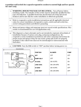
ELECTRICAL CONNECTION
Installation of the cooler must conform to local electrical rules,
regulations and standards.
Important! It is a requirement of Seeley International that all
coolers be connected to a dedicated circuit to the distribution
board, with a separate circuit breaker and incorporate a separate
isolation switch in accordance with the local wiring rules.
The following specications for the cooler electrical supply are
required: 115V/60Hz Single Phase.
It is up to the installer to provide a controller and mains power
should be wired through the controller.
A system wiring diagram is provided below
ILL2838-A
ILL2842-A
The electrical enclosure contains three separate 3AG/3AB slow
blow fuses for over current protection on each of the active lines
for High/Low Speed and the Pump which are contained within
the DIN rail setup. The fuse ratings are as follows:
High Speed - 15A
Low Speed - 10A
Pump - 3A
DIN Rail Setup:
The cooler utilizes a DIN rail for the electrical connection.
The motor and pump will be installed on the DIN rail from
the factory and will not need to be touched. When connecting
the controller/mains power to the unit, pass the cable through
the cable gland at the bottom of the enclosure. The ends of
the cable should be stripped back. Insert the cable into its
corresponding position on the DIN rail and secure it in place by
tightening the screw.
When complete, replace the cover on the enclosure.
ILL2916-A
ILL2839-A
ILL2919-A

EVAPORATIVE COOLER INSTALLATION MANUAL
|
11
Route any of the excess pump cord through the clip as shown.
Once the water level is set correctly, isolate the electrical
enclosure.
Important! Do not connect the power until the water level is set.
WARNING! Do not run the pump while the pad frames are o
and the fan is on.
ILL1061-C
WATER PUMP
If the level is too high rotate the oat clockwise. Drain some water
from the tank and allow it to rell to the new set point.
If too low rotate the oat in an counter-clockwise direction. The
correct water level is approximately 5mm below the surface of
the tank the oat valve is mounted on. It is advisable to check the
water level again after the oat valve washer has “bedded in”.
ILL998-D
Allow the tank (reservoir) to ll with water. The oat valve will
eventually stop the water from entering the cooler. Wait for this
to happen and check the water level.
ILL997-C
SETTING THE WATER LEVEL
Clip in tank
COMMISSIONING THE COOLER
ILL976-D
REFITTING THE PAD FRAMES
Ret the pad frames by locating the bottom edge in the tank
groove, then push the top into the lid.

12
|
COMMISSIONING COMPLETETION CHECKLIST
COOLER
□ SECURE - The cooler is secure and level on the roof jack
using all xings supplied.
□ SEALED - The roof jack and all penetrations are correctly
ashed and sealed.
PLUMBING
□ FLUSHED - The water pipes were ushed of any foreign
materials before connection to the cooler was made.
□ NO EXTERNAL LEAKS - The water is connected with no
leaks at ttings.
□ NO INTERNAL LEAKS - Check the internal water hose is
securely tted to water distribution spreader on the lid and to
the pump.
□ SECURE - Water pipes are correctly saddled as per plumbing
regulations.
□ OWNER INSTRUCTIONS - The owner has been instructed
on how to isolate the water to the system in case of
emergency.
Bleed Funnel
□ INSTALLED - The drain valve is installed correctly, as detailed
in this installation manual.
□ DISCHARGE - The drain water does not discharge onto the
roof surface.
□ WATER LEVEL - Water level has been set correctly, as
detailed in this installation manual.
□ TESTED - Drain the tank manually. Check the drain ttings
and pipes, making sure there are no leaks.
POWER
□ REGULATIONS - The power supply adheres to all local and
national regulations and is wired back to the distribution board
on its own separate circuit.
□ CHECK CABLES - Cables have been correctly connected to
the control boxes:
□ Power supply
□ Motor cable(s)
□ Pump cable
□ OWNER INSTRUCTIONS - The owner has been instructed
how to electrically isolate the unit at the meter box in case of
an emergency.
DUCTWORK
□ NO LEAKS - All ducts are hung correctly and there are no air
leaks..
□ QUIET - Check that the cooler runs quietly and with an even
distribution of air to all outlets.
□ AIR BALANCE – The air balance for all outlets has been
adjusted to the customer’s satisfaction.
FLUSHING CHILLCEL PADS
□ PADS FLUSHED - To prevent initial start-up odours from the
cooling pads, it is a requirement to ush water through them
and drain the tank. Operate in PUMP or COOL mode on low
speed for 5 minutes, then drain the tank. Repeat several
times if necessary.
FINAL TEST
□ Once you are satised that the cooler is installed and
commissioned correctly, run the cooler and ensure that
everything is working as it should.
CUSTOMER HANDOVER
□ Principles of Ducted Evaporative Cooling explained.
□ How far the windows need to be opened.
□ How to turn the cooler on.
□ How to operate the controller.
□ How to drain the cooler.
□ How to turn the power and water o.
□ Maintenance requirements.
□ The customer has been given the Owner’s Manuals &
Warranty Card.
CLEAN-UP
□ All the installation rubbish has been removed and, if
applicable, any property damage repaired. The customer
should not be able to tell you were there, besides placement
of the new equipment.
FINAL CHECK
□ With all side panels in place and the unit running for a short
period in cooling mode, ensure all pads have even water
saturation and there are no visible water leaks

EVAPORATIVE COOLER INSTALLATION MANUAL
|
13
TROUBLE SHOOTING
Symptom Cause Action
Inadequate cooling Under-sized cooler. Replace with larger cooler.
Under-sized ducts. Carry out cooling load design to determine correct size unit,
ducting and outlets required.
Clogged or dirty cooling pads. Clean or replace pads.
Dry pads or lack of water while cooler is operating. Check water distribution system for possible obstruction in
hoses. Check pump.
Insucient air discharge openings or inadequate exhaust
from building, causing high humidity and discomfort.
Make sure there is adequate provision for exhausting stale
air from building (open windows and doors).
Excessive ambient humidity (see also item above regarding
inadequate exhaust).
On days during summer when ambient humidity is high the
cooler will not reduce the temperature as much as on drier
days. There is no remedy except to shut o the pump.
Noisy cooler Fan out of balance due to dirt, etc. Clean the fan.
Too much back pressure.
Tight duct bends.
Grilles too small.
Re-evaluate design; improve duct layout; change grille sizes.
Pump fails to operate Fuse blown Check pump for faults. Replace fuse.
Pump motor failure. Replace pump.
Fan fails to start Motor fuse blown Check cause of overload. Replace fuse
Fan motor burned out. Replace motor.
Low system voltage. Consult with power supply authority.
Pump runs but no water circulation
or Pump runs but pads lack water
Insucient water in tank. Adjust oat level.
Water blocked. Check and clean out blockage.
Pump strainer blocked. Clean pump strainer.
Insucient water supply pressure. Check and conrm water supply pressure
Continuous overow of water Float valve adjustment not correct. Adjust oat valve.
Heavy pad deposits. Clean or replace pads.
Water entering cooler outlet Loose water hose connections. Tighten connections.
Water hose broken. Replace cracked or broken hoses.
Cover not tted on oat valve. Replace oat valve.
Pads not tted correctly into pad frames. Install pad frame correctly.
Incorrect or damaged pads. Replace with new Chillcel pads.
Unpleasant odour New cooler pads. Fill tank, run pump for a short period to wash pads, drain
tank, rell and repeat several times if odour persists. Odour
will dissipate after a number of hours of operation.
Cooler located near source of unpleasant odour. Remove source of odour or relocate cooler.
Algae in tank water. Drain pan, clean thoroughly with strong cleansing agent,
rell, change pads.
Pads remain wet after shut down. Run fan on "vent/fan" for 10 minutes after cooling cycle to dry
pads out.
Heavy pad deposits. Clean or replace pads.

14
|
EXPLODED VIEW
Part ID Description QTY
1 Motor 1
2 Venturi 1
3 Fan 1
4 Mount for Electrical enclosure 1
5 Electrical enclosure 1
6 Pump 1
7 Float Valve 1
8 Bleed Funnel 1
9 Bush for Bleed Funnel 1
10 Chillcel Pad 4
11 Pad Frame 4
12 Lid 1
13 Corner Pillar 4
14 Tank 1
15 Installation Screws 16
16 Duct Adaptor 1 set
ILL2840-A

EVAPORATIVE COOLER INSTALLATION MANUAL
|
15
USER SAFETY
IMPORTANT SAFETY INSTRUCTIONS
READ AND SAVE THESE INSTRUCTIONS
FOR FUTURE REFERENCE.
WARNING - TO REDUCE THE RISK OF
FIRE, ELECTRIC SHOCK, OR INJURY TO
PERSONS, OBSERVE THE FOLLOWING:
a) Use this unit only in a manner intended by
the manufacturer. If you have questions, contact
the manufacturer.
b) Before servicing or cleaning unit, switch
power o at service panel and lock the service
disconnecting means to prevent power from
being switched on accidentally. When the
service disconnecting means cannot be locked,
securely fasten a prominent warning device,
such as a tag, to the service panel.
IMPORTANT NOTES!
In areas where temperatures can cause water
supply pipes to freeze, a drain down facility
should be provided during the installation. This
drain down facility must be activated prior to
freezing conditions, to avoid possible damage
to the cooler components.
New hose sets supplied with the appliance are
to be used.
Old hose sets (from previous installations)
should not be re-used.
As with any product that has moving parts
or is subject to wear and tear, it is VERY
IMPORTANT that you maintain the product
and have it regularly serviced. It is a condition
of warranty cover for your product that you
comply with all of the maintenance and
service requirements set out in the Owner’s
Manual. Compliance with these requirements
will prolong the life of your product. Further,
it is also a condition of warranty cover that
each item in the Maintenance Schedule in
the Owner’s Manual is performed with the
frequency indicated, by a qualied, licensed
technician, and that the Maintenance Schedule
is properly lled out (i.e. names, signature, date,
and action taken) when the item is completed.
ANY FAILURE TO CARRY OUT THE
REQUIRED MAINTENANCE AND SERVICING
REQUIREMENTS, AND ANY FAILURE TO
PROPERLY FILL OUT THE MAINTENANCE
SCHEDULE, WILL VOID YOUR WARRANTY.

16
|
OPERATING YOUR COOLER
To provide ecient cooling or ventilation the building must have
sucient exhaust openings to the outside of the building.
To assist air ow, open windows and doors that are farthest
from the outlet vent in each room. In these rooms, provide an
exhaust opening 2 times the vent size of the room.
Where the design of the building prevents adequate exhaust,
consideration should be given to the provision of mechanical
extractions, such as an exhaust fan.
Your installer will provide the control switch for the cooler and
explain how to use it.
CONTINUOUS BLEED SYSTEM
During operation, the bleed system will drain small amounts of
water. This ensures fresh water is continually added to dilute
salt accumulation in the water caused through evaporation. This
helps keep the air cooler in good condition and ensure optimum
performance. The bleed rate will depend on local operating
conditions and will be set by the installer.
HEALTH REGULATIONS
In some regions, regulations require that evaporative air coolers
be serviced at specic intervals.
MAINTENANCE
WARNING! As your cooler is mounted on the roof, we
suggest that any maintenance or checks be carried out by
an authorised Seeley International dealer or service agent.
Climbing onto the roof can be hazardous and could result
in injury to you and damage to your property.
For gaining access to the cooler, refer to the Removing Pad
Frame section.
MAINTENANCE SCHEDULE SERVICING
Maintenance Schedule servicing is essential to ensure the
cooler operates eciently for many years. It must be carried out
by a qualied, licensed service technician.
At Seeley International, we manufacture evaporative coolers
from the highest quality materials, and we have designed the
product to provide many years of economical, trouble-free
cooling.
The following pages outline the suitable maintenance
requirements to ensure that your cooler continues to operate
eciently.
We require that the following components and the operation
thereof, be checked/serviced after the rst year, then every 2
years for residential purposes, or every year for commercial
purposes, as Maintenance Schedule servicing. Refer to the
Maintenance Schedule section.
Maintenance Schedule servicing should be performed before
the summer season. It is important to note that all evaporative
coolers have components that may need periodic replacement
(eg. lter pads, hoses, O-rings etc).
MAINTENANCE
Note! Failure to carry out the Maintenance Schedule services
will void your warranty cover.
Note! Maintenance Schedule servicing may be required more
frequently in adverse environmental situations or where the
appliance is installed in non-domestic applications. Please
consult with the installer or service personnel to determine if
more frequent servicing is required.
Access for Servicing and Maintenance
Working at heights requires additional safety precautions.
Required clearances around the cooler for maintenance and
servicing are shown below.

EVAPORATIVE COOLER INSTALLATION MANUAL
|
17
ILL2873-A
High Duty Cycle Operation Maintenance
Only applicable for coolers operating more than 12 hours
per day continuously throughout the year.
The following maintenance program is required in addition to
the servicing required by the Maintenance Schedule:
6 monthly maintenance:
• Inspect the cooler, check the pump, and fan motor.
• Check the pads and replace as required.
• Check and clean the tank and the pump lter.
12 monthly maintenance:
• Replace plastic fan and check motor shaft for wear.
• Water distribution channels.
• Pump.
• Fan motor operation.
• Float valve.
MAINTENANCE
A = Motor
B = Motor to Venturi Mount
C = Venturi
D = Superstealth Fan
E = Grub Screw (secures motor shaft to fan metal
insert)
Before replacing the fuse, switch power o at service panel and
lock the service disconnecting means to prevent power from
being switched on accidentally.
When the service disconnecting means cannot be locked,
securely fasten a prominent warning device, such as a tag to
the service panel.
• Remove the cover of the control enclosure by removing the
6 screws located on the side of the enclosure.
• Open the fuse holder by grasping the tab at the top and
pulling down.
• Remove fuse carefully by pushing it sideways.
• Risk of re.
Replace fuse only with 3/10/15 Amp, 250 Volt fuse
3AG/3AB slow blow fuses. See wiring diagram for correct
fuse location and rating.
• Close the fuse holder and re-attach the cover to the control
enclosure by securing the 6 screws on the side of the
enclosure.
Replacing the Fuse in the Electrical Enclosure
3 fuses are located inside the electrical enclosure as
shown.
ILL2842-A
ILL2915-A
ILL2916-A

18
|
SEASONAL MAINTENANCE
Water Distribution Channels
ILL1103-B
The spreader section of the water distribution system will
need occasional maintenance and cleaning, depending on the
frequency of use, water quality and associated calcication or
solids build-up.
To access the water spreaders, remove the pad frames from the
cooler to expose them.
ILL974-B
ILL976-D
ILL975-C
Insert a at screw driver tip into the slot as shown and lever until
disengagement occurs.
Take hold of the pad frame and pull it towards you until the
internal side clips disengage.
Pivot the pad frame outwards and lift up.
Take care not to damage the pad.
REMOVING PAD FRAMES
/