Adtec Mirage Technical Manual

Type
Technical Manual

This manual is also suitable for

MIRAGE
BROADCAST MPEG 2 PLAYER
SOLOIST 2
BROADCAST MPEG 2 PLAYER
ADTEC, INC.
INNOVATIVE BROADCAST AUTOMATION
WWW.ADTECINC.COM
Sales/Customer Service/Technical Support
Adtec, Inc.
408 Russell Street
Nashville, TN 37206
(615) 256-6619
Fax: (615) 256-6593
Sales: (615) 256-6619
Technical Support: (615) 256-7753
Production/Engineering/Research & Development
Adtec, Inc
2231 Corporate Square Blvd.
Jacksonville, FL 32216
WWW.ADTECINC.COM
Table Of Contents
i. Contact Information
I. Quick Start-Up Guides
Mirage-Soloist 2 Quick Start-Up Guide
Ethernet Quick Start-Up Guide
II. Mirage Introduction
III. Soloist 2 Introduction
IV. Symphony
Locations
IFP (In Field Programming Guide)
Console
Using Console
Directory
Configuration
Communication
Audio/Video
Transport
Time
Networking
Features
Manufacture
List
Using Lists
DVC Files
Schedule
Using Schedules
Dvc Files
V. Terminal Mode Command Interface
Mirage-Soloist 2 Commands
Terminal Mode Error Appendix
VI. Network Troubleshooting
VII. DDSN Appendix
VIII. Parallel Port Appendix
Parauto.DVC
IX. Technical
Soloist 2 / Mirage – Start-up Guide
QUICK START-UP GUIDE
Creating a Symphony-Net Location
1. Connect DB-9 or DB-25 adapter to open COM port on PC.
2. Run telephone cord from adapter to COM IN on back of device.
3. Open Adtec’s Symphony-Net Software
4. Choose your device. (Soloist 1, Soloist 2, or Mirage)
5. Create a location.
Click (+) sign and enter a location name.
Enter phone number if using a modem. Remember to input the modem string into the unit
as well.
Enter port type.
Enter the Unit Names exactly as they are entered into your device.
Factory default unit names are SOLOIST (Soloist 1 and Soloist 2) and MIRAGE
(Mirage)
Enter Baud Rate = 38,400; Data Bits = 8; Stop Bits = 1; and Parity = none
An Asterisk (*) is the wild card name for all units. Only use the (*) when connected to a single
unit, otherwise all units in the communications chain will receive your commands.
6. Save and close Location.
7. Open Console.
8. Open your location from
CONNECTIONS
drop down menu. (Bottom right corner of main
screen)
9. Click on
UNITS
drop down list and select your individual unit.
10. Information will appear immediately on the Control Panel and the Directory behind Control
Panel.
11. YOU are CONNECTED.
Soloist 2 / Mirage – Start-up Guide
QUICK START-UP GUIDE
Using
Symphony-Net / Console
1. After creating your
LOCATION
.
2. Open Console Applet.
3. Open your location from
CONNECTIONS
drop down menu. (Bottom right corner of main
screen)
4. Click on
UNITS
drop down list and select your individual unit (The same name as in your
LOCATION.
5. Information will appear immediately on the Control Panel and in the Directory behind
Control Panel.
6. YOU are CONNECTED.
** A quick way to check if your connected is to type * _(enter) in the TERMINAL MODE. The
response should be “0” or “OK”.
Directory
The Directory provides a textual inventory of clips residing on the hard drive(s) in the Soloist. The file
Name, Drive, Disk (Partition), Spot number, Length, File size (MB), Data Rate (Mbs), Date encoded, and
Time encoded are provided.
LIST
Creating a Sequential Playback List
Under the List Tab in Console, Drag and Drop SPOT NAMES (MPEG clips) from the directory window
on the left to the List window on the right.
This List is now only on your Desktop PC.
SEND this list to the Soloist.
Press NV- SAVE to save the list to Non-Volatile Memory.
CONFIGURATION
The
configuration
will play a large role in how the list is executed, be sure that the configuration
variables match the desired functionality for the list.
Recommended Configuration settings for Lists are:
Setting Option
Repeat All
Startup On
Remember to NV-SAVE the new configuration
Soloist 2 / Mirage – Start-up Guide
QUICK START-UP GUIDE
SCHEDULE TAB
Creating a Schedule
Schedule adds the Weekday, Month, Date, Year, Hour, Minute, Second and Frame options to a list.
Make sure the Schedule Running Button is checked prior to sending the schedule or it will not
work.
Under the Schedule Tab in Console, Drag and Drop SPOT NAMES (MPEG clips) from the directory
window on the left to the Schedule window on the right.
Assign Date and Time to each clip.
SEND this schedule to the Soloist.
Press NV- SAVE to save the schedule to Non-Volatile Memory.
The
configuration
of the unit will play a large role in how the schedule is executed, be sure that the
configuration variables match the desired functionality for the list.
Recommended Configuration settings for schedules are:
Setting Option
Repeat
Off
Startup
Off
The Schedule Linking Feature
Once the first program in your schedule is assigned a time, single click in its link box to the left, drag
through all additional programs in your schedule. Start times will be automatically assigned. This feature
is particularly useful when a schedule of lists is required on a repeating or day-to-day basis.
Speed Button Descriptions
Configuration Speed Button Table
Speed Button Function
NV-Erase Clear the Non Volatile (Flash) memory
NV-Load Load (Get) the Non Volatile (Flash) memory settings and display to desktop
NV-Save Save (Send) the Non Volatile (Flash) memory settings from the desktop to
Soloist
Defaults Set unit configuration to default, must save after default has been selected
Soloist 2 / Mirage – Start-up Guide
QUICK START-UP GUIDE
List & Schedule Speed Button Table
Speed Button Function
NV-Erase Clear the Non Volatile (Flash) memory
NV-Load Load the Non Volatile (Flash) memory settings into Volatile Memory
NV-Save Save (Send) the Non Volatile (Flash) memory settings from the desktop to
Soloist
Clear Clear the list or schedule from the Volatile Memory only
Get Get the list or schedule from the non-volatile memory and display on the
desktop
Send Send the list or schedule from the desktop to the Soloist volatile (erasable)
memory. The NV-Save must be clicked after the send command is issued.
The sequence is Send then NV-Save to save a list to Non-volatile memory.
Non-Volatile Memory (NV)
The configuration settings allow the user to customize the Soloist to perform exactly as desired. There is
no need to set switches for specific characteristics to be defined. The non-volatile memory is in the form
of a Flash ROM. It can be re-written to an infinite number of times. Once the NV-Save speed button is
selected, the user will be prompted "You are about to save the Configuration in the Soloist to the non-
volatile memory…ARE YOU SURE?" click Yes to proceed or No to cancel. Once yes is clicked, the
Soloist will now react with the configuration characteristic defined and saved in the non-volatile memory.
Soloist 2 / Mirage – Ethernet Setup
QUICK START-UP GUIDE
Check Connection with Unit (s)
1. Connect DB-9 or DB-25 adapter to open com port on PC.
2. Run telephone cord from adapter to COM IN on back of device.
3. Open Adtec’s Symphony-Net Software
4. Choose your device. (Soloist 2 or Mirage)
5. Create a location. Open Locations.
Click (+) sign and enter a location name.
Enter phone number if using a modem.
Enter port type.
Enter the Unit Names exactly as they are entered into your device.
Factory default unit names are SOLOIST (Soloist 2) and MIRAGE (Mirage)
Enter Baud Rate = 38,400; Data Bits = 8; Stop Bits = 1; and Parity = none
An Asterisk (*) is the wild card name for all units. Only use the (*) when connected to a single
unit, otherwise all units in the communications chain will receive your commands.
6. Save and close Location.
7. Open Terminal.
8. Open your location from
CONNECTIONS
drop down menu. (Bottom right corner of main
screen)
9. Type * _(enter). The response should be “0” or “OK”.
10. YOU are CONNECTED.
Using
Symphony-Net / Console
1. After creating your
LOCATION
.
2. Open Console Applet.
3. Open your location from
CONNECTIONS
drop down menu. (Bottom right corner of main
screen)
4. Click on
UNITS
drop down list and select your individual unit (The same name as in your
LOCATION.
5. YOU are CONNECTED.
Soloist 2 / Mirage – Ethernet Setup
QUICK START-UP GUIDE
Upgrade Firmware Through IFP
It may be necessary for you to upgrade to a more recent version of firmware in order to make the Ethernet
Feature work properly.
1.
Open Adtec’s Symphony-Net Software (July Version or Later)
2.
Choose your device. (Soloist 2 or Mirage)
3.
Open IFP Applet.
4.
Select Boot Key Mode* or Non Boot Key Mode
5.
Select Units (Left Window) to upgrade firmware
6.
Browse Hard Drive for S19 File to upload
a.
Date will appear under top window. Make sure that it is the appropriate date
code.
7.
Click Program Application Button
8.
Monitor Progress in right hand window.
*The boot key (9-pin key with pins 4 and 9 soldered together) must be placed on the unit prior uploading
firmware. The unit must then be reset and the user must verify the alternating video and drive lights on
the front panel. After the unit receives new firmware, the boot key must be removed and the unit must be
reset.
Boot Key
NOTE: If you are using a July Version or later Version of Firmware before upgrading, you do not have
to use the Boot Key. You can connect to the Soloist through the Com Port and upgrade the Firmware.
This is very useful for upgrading your Soloist over a modem. The unit can still play function while the
firmware is being loaded. However, you will have to Reset the unit in order for the new firmware to take
effect.
Soloist 2 / Mirage – Ethernet Setup
QUICK START-UP GUIDE
Install Feature Keys
Feature Keys will enable special feature of the Soloist2. Otherwise the unit may flash the video and drive
lights simultaneously. It is possible to change this setting through Terminal Mode, but it is recommended
to use the Console’s Interface.
1. Open Adtec’s Symphony-Net Software (July Version or Later)
2. Choose your device. (Soloist 2 or Mirage)
3. Open Console Applet.
4. Connect to unit (s) by selecting the CONNECTION area in the bottom right corner of the
screen.
5. Select Unit in top left-hand corner. There should already be a location for unit (s) to
program.
6. Select FEATURES tab. The features of the selected unit should appear along with the
Permanent and Temporary Locks.
7. Enter the appropriate FEATURE key for each feature to be enabled. Remember to press
<ENTER>. The feature should turn from Disabled (RED) to Enabled (GREEN)
immediately.
8. Repeat above step for each Feature to enable and repeat process for each unit (s) to be
changed.
Be aware that there is an email form from Adtec that will automate this process. If you have multiple
units and they are daisy-chained together through the RS-232 port, you may consider this option. All
features of the units will be updated automatically.
NOTE:
This option has a problem with email
received from AOL.
Set HOSTMODE Properties
Adtec refers to the LAN functions of a unit as the HOSTMODE properties of the unit. These properties
give an individual identity to the unit when you access the unit via Ethernet. Each command is further
explained in the Command Interface Manual. The commands may be executed from Soloist Console in
the Symphony software or directly from terminal.
1. Set Hostmode of Unit. The first soloist is usually set as the SERVER and the rest are
Clients.
2. Set the IPAddress of the Unit. This is four-digit decimal form. ###.###.###.###
3. Set the IPMask of the Unit. This is four-digit decimal form. ###.###.###.###
4. Set the GatewayIPAddress of the unit if applicable. This is only used when a gateway is
involved. The soloist can support up to 4 gateway addresses.
5. Set the HostIPAddress of the unit if applicable. This is used when you want the clients to
mirror the server. The soloist can support up to 4 Host addresses.
6. Set the HostTimer of the unit. This is applicable in a mirror setting only. It is the delay
in seconds between the clients querying the server for new information.
7. Set the ServerUserPassword. Default is SOLOIST, NONE. Both must be in CAPS.
8. Set the ClientUserPassword. Default is SOLOIST, NONE. Both must be in CAPS.
Soloist 2 / Mirage – Ethernet Setup
QUICK START-UP GUIDE
Power Off
The Soloist(s) must be powered down in order for the new HOSTMODE properties to take effect. Once
you power up the Soloist(s), the new properties will take effect.
Ping
After power up, you will need to PING the unit(s) to see if they will respond. Ping is a useful command
that will address the unit via its new IPAddress and respond with the time that it took the unit to respond.
The PING command is further explained in the Command Interface Manual.
Rear of Soloist showing the Ethernet Port
NOTE: Your Soloist may be configured differently.
Mirage Intro
MPEG 2 PLAYER Version 3.0
Intro-Page 1 of 6
ADTEC, Inc. USA
INTRO
INTRO
Mirage Introduction
The Mirage represents years of engineering and market research culminating
into one simple, reliable, economical and powerful video tool. At its core, the
Mirage utilizes a high-speed 32-bit RISC CPU operating under ADTEC’s own
deterministic multitasking operating system. The core CPU is tightly integrated
with MPEG decoding, memory, drive host control and digital to analog circuitry
to provide the highest level of quality and reliability available. The Mirage will
provide years and years of total maintenance free operation without the need or
knowledge of sophisticated computers and operating systems.
Identifier Description
A Reset switch. Must be held for one second to initiate reset.
B Power LED illuminates when AC power is applied to unit.
C Video LED illuminates during video playback.
D Drive LED illuminates during IDE host controller activity.
E Drive bay for primary, IDE
Mirage Front with included removable IDE hard drive.
Mirage Intro
MPEG 2 PLAYER Version 3.0
Intro- Page 2 of 6 ADTEC,
Inc. USA
INTRO
INTRO
Connector Description
A Chassis ground.
B AC line input, 3-pin computer power plug. Includes 6’ cable. (Auto range 70-240 VAC input)
C SOLO210BASET (10 Base T). Expansion port 2.
D SOLOBALYC (Balanced audio, Y/C, RGB, YUV) expansion port. Expansion port 1.
E Parallel control port.
F RS-232 communications port THRU. (Unlimited loop-through capabilities)
G RS-232 communications port IN. (Unlimited loop-through capabilities) Units require unique names to
address individually.
H Power cord strain relief connections
I 10 Base T Ethernet Busy LED.
J 10 Base T Ethernet Link LED.
K 10 Base T Ethernet RJ-45 jack.
L Ethernet hardware address. (48 bit address set in hardware, IP address selected in firmware configuration)
M Balanced RIGHT audio output, 600 Ohm output impedance. (Only included with SOLO2BALYC
option)
N Balanced LEFT audio output, 600 Ohm output impedance. (Only included with SOLO2BALYC
option)
O Y/C output. 4 pin din connector. (Only included with SOLO2BALYC option)
P Video output number 1, 75 Ohm.
Q Video output number 2, 75 Ohm.
R Unbalanced LEFT audio output, 56K Ohm output impedance.
S Unbalanced RIGHT audio output, 56K Ohm output impedance.
Mirage rear panel with optional Balanced Audio/YC and 10 Base T Ethernet options
Mirage Intro
MPEG 2 PLAYER Version 3.0
Intro- Page 3 of 6 ADTEC,
Inc. USA
INTRO
INTRO
Physical Concerns
Rack Mount Applications:
The Mirage was designed to be rack mounted and requires only one rack unit
(1RU). It does NOT require blank spaces above or below to remain within it’s
designed operating temperatures. The Mirage integrates a built in fan with side
panel discharge, make sure the side discharge has at least 1” of clear space to
allow for airflow.
Non Rack Mount Applications:
The Mirage can be tabletop or desk mounted as it ships with four rubber feet to
prevent skid or slipping on Formica finishes. In this application, make sure that
no heavy objects (over 25 pounds) are placed on top of the unit as this may
cause damage to the drives.
Power Concerns
Power Supply:
The Mirage ships with a six (6) foot standard SJT power cord with a three (3)
pin US type plug. Optionally, a European 3 PIN cord with plug is available. The
unit incorporates a universal input switch mode power supply. It carries the CE,
UL, CSA and TUV safety certifications. Valid input ranges from 70 to 240 volts
AC (VAC), 50 Hz or 60 Hz and uses between 20 and 65 watts based on the
number and type of hard drives used.
Audio and Video Concerns
Video Connections:
The MIRAGE uses video industry standard BNC connectors for video
connections.
\
Units can be rack mounted with
out fill panels between them.
%
The Mirage can be configured for
Composite and optional YC video
Audio Connections:
Mirage Intro
MPEG 2 PLAYER Version 3.0
Intro- Page 4 of 6 ADTEC,
Inc. USA
INTRO
INTRO
The Mirage ships standard with RCA jack, Unbalanced (Hi impedance -10 dB,
56 K Ohm) audio connectors for left and right channels. If the SOLOBALYC
option is purchased, removable screw terminal (RST) connectors will be
supplied to facilitate low impedance (+4 dB, 600 Ohm) balanced audio. In
addition, a four (4) pin din connector.
Communications Concerns
Control Connectors:
The MIRAGE incorporates Parallel and Serial RS232 control. The Parallel port
utilizes a DB9 male connector and the RS232 ports utilize RJ-11 telephone
connectors. For specific information regarding the protocol and pin out, see the
Technical section.
Communications Connections:
The MIRAGE provides multi drop loop-through RS232 to allow a single PC
communications port or serial controller access to multiple units. Two RJ-11
connectors make up the In and Through connections. Adapters are provided to
connect the MIRAGE directly to a 9-pin or 25-pin PC communications port.
Hard Drive Concerns
The Mirage ONLY recognizes drives formatted using FAT 16. The DOS
FDISK utility limits the partition size to 2 Gigabytes; however, the Mirage can
partition and format drives with up to 4 Gigabyte FAT 16 partitions. The Mirage
can see up to 32 partitions per physical drive (128 Gigabytes/Drive). The Mirage
chassis can facilitate one (1) IDE hard drive mounted in 5.25” removable bay.
Summary:
The MIRAGE was designed to replace VCR’s and Laser (Video) Disk Players.
It will provide many years of high quality reliable video and audio. Should you
require technical support or supplies contact ADTEC at 615-256-6619 or
www.adtecinc.com.
%
The Mirage can easily be
controlled via serial or parallel
interfaces.
%
An unlimited number of units can
be controlled from one (1) RS232
serial port.
\
FAT 16 is the only file system the
Mirage recognizes. The Mirage
partitioned and formatted drives
can be seen in Win 95 and NT.
\
The Mirage ONLY uses IDE hard
drives.
Mirage Intro
MPEG 2 PLAYER Version 3.0
Intro- Page 5 of 6 ADTEC,
Inc. USA
INTRO
INTRO
MPEG Encoding Parameters
Item Spec Type Notes
MPEG 1 ISO-11172-2 System Data rates from 0.5 Mbs to 5 Mbs
MPEG 2 ISO-13818 Program Data rates from 1 Mbs to 8 Mbs ***
GOP NA NA Adjustable from 1 to 15, Full IBP, IP or I only.
GOP markings are preferred.
Video
Resolution
NTSC
NA 720-480, 30 fps
352-480, 30 fps
352-240, 30 fps
Full D1
Half D1
SIF
Color Frequency: 3,579,545 Hz
Video
Resolution
PAL
NA 720-576, 25 fps
352-576, 25 fps
352-288, 25 fps
Full D1
Half D1
SIF
Color Frequency: 4,433,618.75 Hz
Video
Resolution
PAL-M
NA 720-480, 30 fps
352-480, 30 fps
352-240, 30 fps
Full D1
Half D1
SIF
Color Frequency: 3,575,611.49 Hz
Video
Resolution
PAL-N
NA 720-576, 25 fps
352-576, 25 fps
352-288, 25 fps
Full D1
Half D1
SIF
Color Frequency: 3,582,056.25 Hz
Audio
Sampling
NA Mono, Dual Mono,
Stereo or Joint Stereo
Sampling rates of 44.1 kHz or 48 kHz.
Audio ISO-11172-3
Layer 1 Data rates supported for Layer 1 are 32 Kbits/s
to 448 Kbits/s in 32 K steps.
Audio ISO-11172-3
Layer 2 Data rates supported for Layer 2 are 64, 96, 112,
128, 160, 192, 224, 256, 320, 384 Kbits/s. Free
formatted or variable audio bit rates are not
compatible.
*** The Mirage is limited to a maximum of 8 Mbs total Program
Stream data rate for MPEG 2. Do not set the video data rate to 8
Mbs as the audio will add to this number and the Mirage will not
register the files!
\
The terminal directory command
supports a unified listing that will
show all files with attributes. Type:
<unit name> dir u
The Mirage will respond with a
complete unified listing of all files.
MPEG files with higher than 8 Mbs
data rates will be displayed and
commented as such.
Mirage Intro
MPEG 2 PLAYER Version 3.0
Intro- Page 6 of 6 ADTEC,
Inc. USA
INTRO
INTRO
Declaration of Conformity
Manufacturers Name: ADTEC, Inc.
Manufacturer Address: 408 Russell Street, Nashville, TN. 37206 USA
Responsible Person: Kevin Ancelin, Vice President Operations
Product Model Number: Mirage
Description of Product: ADTEC’s Mirage MPEG 2 player was designed to
store and decode MPEG1 and MPEG2 video. The device is essentially an
embedded computer containing the following features:
Real-time 32 bit operating system
IDE hard drive control
File system
Serial inputs and outputs
ASCI command control support (Terminal Mode)
Parallel inputs and outputs
Ethernet
Embedded Motorola CPU with DRAM
NTSC and PAL video outputs
Universal input power supply
Real Time Clock
Directive Complied: EMC 89/336/EEC
Conforming Standards:
EN 55022: 1994 Radiant and Conducted Emissions Testing
EN 50082-1: 1992 Generic Immunity
IEC 801-2: 1991 Electrostatic Discharge, Immunity Testing
IEC 801-3: 1984 Radiant Electromagnetic Fields, Immunity Testing
IEC 801-4: 1988 Electrical Fast Transient/Burst, Immunity Testing
I, the undersigned hereby declare that the Mirage conforms to the above
Directives and Standards.
Manufacturer:
Signature Date
Name Kevin Ancelin Title VP Operations
SOLOIST 2 Intro
BROADCAST MPEG 2 PLAYER Version 2.0
Intro-Page 1 of 6
ADTEC, Inc. USA
INTRO
INTRO
Soloist 2 Introduction
The Soloist 2 represents years of engineering and market research culminating
into one simple, reliable, economical and powerful broadcast tool. At its core,
the Soloist 2 utilizes a high-speed 32-bit RISC CPU operating under ADTEC’s
own deterministic multitasking operating system. The core CPU is tightly
integrated with MPEG decoding, memory, drive host control and digital to
analog circuitry to provide the highest level of quality and reliability available.
The Soloist 2 will provide years and years of total maintenance free operation
without the need or knowledge of sophisticated computers and operating
systems.
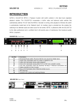
Identifier Description
A Reset switch. Must be held for one second to initiate reset.
B Power LED, illuminates when AC power is applied to unit.
C Video LED, illuminates during video playback.
D Drive LED, illuminates during either SCSI or IDE host controller activity.
E Link LED, illuminates when the electrical 10 Base T Ethernet connection is made
correctly to a hub or server.
F Busy LED illuminates when Ethernet activity occurs.
G Drive bay for primary, IDE or SCSI
H Drive bay for secondary, IDE or SCSI
Soloist 2 Front with two removable hard drives
SOLOIST 2 Intro
BROADCAST MPEG 2 PLAYER Version 2.0
Intro- Page 2 of 6
ADTEC, Inc. USA
INTRO
INTRO
Connector Description
A Chassis ground.
B AC line input, 3-pin computer power plug. Includes 6’ cable. (Auto range 70-240 VAC input)
C SOLO210BASET (10 Base T) and External SCSI 2 drive expansion port. Expansion port 2.
D SOLO2BALYC (Balanced audio, Y/C, RGB, YUV) expansion port. Expansion port 1.
E RS422A control port.
F Parallel control port.
G RS-232 communications port THRU. (Unlimited loop-through capabilities)
H RS-232 communications port IN. (Unlimited loop-through capabilities) Units require unique names to
address individually.
I Product label area.
J 10 Base T Ethernet Busy LED. (Only used when installed in Soloist 1 to Soloist 2 upgrade)
K 10 Base T Ethernet Link LED. (Only used when installed in Soloist 1 to Soloist 2 upgrade)
L 10 Base T Ethernet RJ-45 jack.
M Ethernet hardware address. (48 bit address set in hardware, IP address selected in firmware configuration)
N Balanced RIGHT audio output, 600 Ohm output impedance. (Only included with SOLO2BALYC
option)
O Balanced LEFT audio output, 600 Ohm output impedance. (Only included with SOLO2BALYC
option)
P Y/C output. 4 pin din connector. (Only included with SOLO2BALYC option)
Q Y output of Y/C on BNC connector. (Only included with SOLO2BALYC option)
R C output of Y/C on BNC connector. (Only included with SOLO2BALYC option)
S Video output number 1, 75 Ohm.
T Video output number 2, 75 Ohm.
U SYNC input, 75 Ohm, Black Burst or Digital TTL sync. Genlock input (firmware upgrade
required)
V Unbalanced LEFT audio output, 56K Ohm output impedance.
W Unbalanced RIGHT audio output, 56K Ohm output impedance.
Soloist 2 rear panel with optional Balanced Audio and 10 Base T Ethernet options
SOLOIST 2 Intro
BROADCAST MPEG 2 PLAYER Version 2.0
Intro- Page 3 of 6
ADTEC, Inc. USA
INTRO
INTRO
Physical Concerns
Rack Mount Applications:
The Soloist 2 was designed to be rack mounted and requires only one rack unit
(1RU). It does NOT require blank spaces above or below to remain within it’s
designed operating temperatures. The Soloist 2 integrates a built in fan with side
panel discharge, make sure the side discharge has at least 1” of clear space to
allow for airflow.
Non Rack Mount Applications:
The Soloist 2 can be tabletop or desk mounted as it ships with four rubber feet to
prevent skid or slipping on Formica finishes. In this application, make sure that
no heavy objects (over 25 pounds) are placed on top of the unit as this may
cause damage to the drives.
Power Concerns
Power Supply:
The Soloist 2 ships with a six (6) foot standard SJT power cord with a three (3)
pin US type plug. Optionally, a European 3 PIN cord with plug is available. The
unit incorporates a universal input switch mode power supply. It carries the CE,
UL, CSA and TUV safety certifications. Valid input ranges from 70 to 240 volts
AC (VAC), 50 Hz or 60 Hz and uses between 20 and 65 watts based on the
number and type of hard drives used.
Audio and Video Concerns
Video Connections:
The SOLOIST 2 uses video industry standard BNC connectors for video and
SYNC connections.
\
Units can be rack mounted with
out fill panels between them.
%
The Soloist 2 can be configured for
Composite, YC, Component
(Separate SYNC), and RGB
(SYNC). See Configuration for
more specifics.
  • Page 1 1
  • Page 2 2
  • Page 3 3
  • Page 4 4
  • Page 5 5
  • Page 6 6
  • Page 7 7
  • Page 8 8
  • Page 9 9
  • Page 10 10
  • Page 11 11
  • Page 12 12
  • Page 13 13
  • Page 14 14
  • Page 15 15
  • Page 16 16
  • Page 17 17
  • Page 18 18
  • Page 19 19
  • Page 20 20
  • Page 21 21
  • Page 22 22
  • Page 23 23
  • Page 24 24
  • Page 25 25
  • Page 26 26
  • Page 27 27
  • Page 28 28
  • Page 29 29
  • Page 30 30
  • Page 31 31
  • Page 32 32
  • Page 33 33
  • Page 34 34
  • Page 35 35
  • Page 36 36
  • Page 37 37
  • Page 38 38
  • Page 39 39
  • Page 40 40
  • Page 41 41
  • Page 42 42
  • Page 43 43
  • Page 44 44
  • Page 45 45
  • Page 46 46
  • Page 47 47
  • Page 48 48
  • Page 49 49
  • Page 50 50
  • Page 51 51
  • Page 52 52
  • Page 53 53
  • Page 54 54
  • Page 55 55
  • Page 56 56
  • Page 57 57
  • Page 58 58
  • Page 59 59
  • Page 60 60
  • Page 61 61
  • Page 62 62
  • Page 63 63
  • Page 64 64
  • Page 65 65
  • Page 66 66
  • Page 67 67
  • Page 68 68
  • Page 69 69
  • Page 70 70
  • Page 71 71
  • Page 72 72
  • Page 73 73
  • Page 74 74
  • Page 75 75
  • Page 76 76
  • Page 77 77
  • Page 78 78
  • Page 79 79
  • Page 80 80
  • Page 81 81
  • Page 82 82
  • Page 83 83
  • Page 84 84
  • Page 85 85
  • Page 86 86
  • Page 87 87
  • Page 88 88
  • Page 89 89
  • Page 90 90
  • Page 91 91
  • Page 92 92
  • Page 93 93
  • Page 94 94
  • Page 95 95
  • Page 96 96
  • Page 97 97
  • Page 98 98
  • Page 99 99
  • Page 100 100
  • Page 101 101
  • Page 102 102
  • Page 103 103
  • Page 104 104
  • Page 105 105
  • Page 106 106
  • Page 107 107
  • Page 108 108
  • Page 109 109
  • Page 110 110
  • Page 111 111
  • Page 112 112
  • Page 113 113
  • Page 114 114
  • Page 115 115
  • Page 116 116
  • Page 117 117
  • Page 118 118
  • Page 119 119
  • Page 120 120
  • Page 121 121
  • Page 122 122
  • Page 123 123
  • Page 124 124
  • Page 125 125
  • Page 126 126
  • Page 127 127
  • Page 128 128
  • Page 129 129
  • Page 130 130
  • Page 131 131
  • Page 132 132
  • Page 133 133
  • Page 134 134
  • Page 135 135
  • Page 136 136
  • Page 137 137
  • Page 138 138
  • Page 139 139
  • Page 140 140
  • Page 141 141
  • Page 142 142
  • Page 143 143
  • Page 144 144
  • Page 145 145
  • Page 146 146
  • Page 147 147
  • Page 148 148
  • Page 149 149
  • Page 150 150
  • Page 151 151
  • Page 152 152
  • Page 153 153
  • Page 154 154
  • Page 155 155
  • Page 156 156
  • Page 157 157
  • Page 158 158
  • Page 159 159
  • Page 160 160
  • Page 161 161
  • Page 162 162
  • Page 163 163
  • Page 164 164
  • Page 165 165
  • Page 166 166
  • Page 167 167
  • Page 168 168
  • Page 169 169
  • Page 170 170
  • Page 171 171
  • Page 172 172
  • Page 173 173
  • Page 174 174
  • Page 175 175
  • Page 176 176
  • Page 177 177
  • Page 178 178
  • Page 179 179
  • Page 180 180
  • Page 181 181
  • Page 182 182
  • Page 183 183
  • Page 184 184
  • Page 185 185
  • Page 186 186
  • Page 187 187
  • Page 188 188
  • Page 189 189
  • Page 190 190
  • Page 191 191
  • Page 192 192
  • Page 193 193
  • Page 194 194
  • Page 195 195
  • Page 196 196
  • Page 197 197
  • Page 198 198
  • Page 199 199

Adtec Mirage Technical Manual

Type
Technical Manual
This manual is also suitable for

Ask a question and I''ll find the answer in the document

Finding information in a document is now easier with AI