Page is loading ...

SATELLINE-M3-TR1/ SATELLINE-M3-TR1 869
User Guide, Version 5.5
1
SATELLINE-M3-TR1
SATELLINE-M3-TR1 869
Radio module
User guide

SATELLINE-M3-TR1/ SATELLINE-M3-TR1 869
User Guide, Version 5.5
2
IMPORTANT NOTICE
All rights to this manual are owned solely by SATEL Oy (referred to in this user guide as SATEL).
All rights reserved. The copying of this manual (without the written permission from the owner)
by printing, copying, recording or by any other means, or the full or partial translation of the
manual to any other language, including all programming languages, using any electrical,
mechanical, magnetic, optical, manual or other methods or devices is forbidden.
SATEL reserves the right to change the technical specifications or functions of its products, or to
discontinue the manufacture of any of its products or to discontinue the support of any of its
products, without any written announcement and urges its customers to ensure, that the
information at their disposal is valid.
SATEL software and programs are delivered ”as is”. The manufacturer does not grant any kind
of warranty including guarantees on suitability and applicability to a certain application. Under
no circumstances is the manufacturer or the developer of a program responsible for any
possible damages caused by the use of a program. The names of the programs as well as all
copyrights relating to the programs are the sole property of SATEL. Any transfer, licensing to a
third party, leasing, renting, transportation, copying, editing, translating, modifying into
another programming language or reverse engineering for any intent is forbidden without the
written consent of SATEL.
SATEL PRODUCTS HAVE NOT BEEN DESIGNED, INTENDED NOR INSPECTED TO BE USED IN ANY
LIFE SUPPORT RELATED DEVICE OR SYSTEM RELATED FUNCTION NOR AS A PART OF ANY OTHER
CRITICAL SYSTEM AND ARE GRANTED NO FUNCTIONAL WARRANTY IF THEY ARE USED IN ANY OF
THE APPLICATIONS MENTIONED.
Salo, FINLAND 2020
Copyright: 2020 SATEL Oy
No part of this document may be reproduced, transmitted or stored in a retrieval system in any
form or by any means without the prior written permission of SATEL Oy. This document is
provided in confidence and must not be distributed to third parties without the express
permission of SATEL Oy.

SATELLINE-M3-TR1/ SATELLINE-M3-TR1 869
User Guide, Version 5.5
3
RESTRICTIONS ON USE
SATELLINE-M3-TR1 radio modem modules have been designed to operate on frequency ranges,
the exact use of which differs from one region and/or country to another. The user of a radio
modem must take care that the device is not operated without the permission of the local
authorities on frequencies other than those specifically reserved and intended for use without a
specific permit.
SATELLINE-M3-TR1 is allowed to be used in the following countries, either on licence free
channels or on channels where the operation requires a licence. More detailed information is
available at the local frequency management authority.
Countries: AT, AU, BE, BG, CA, CH, CY, CZ, DE, DK, EE, ES, FI, FR, GB, GR, HR, HU, IE, IS, IL, IN, IT,
KZ, LT, LU, LV, MX, MT, NL, NO, OM, PL, PT, RU, RO, SE, SG, SI, SK, TR, UA, US, VN and ZA.
Class B digital device statement
Note: This equipment has been tested and found to comply with the limits for a Class B digital
device, pursuant to Part 15 of the FCC Rules. These limits are designed to provide reasonable
protection against harmful interference in a residential installation. This equipment generates
uses and can radiate radio frequency energy and, if not installed and used in accordance with the
instructions, may cause harmful interference to radio communications. However, there is no
guarantee that interference will not occur in a particular installation. If this equipment does cause
harmful interference to radio or television reception, which can be determined by turning the
equipment off and on, the user is encouraged to try to correct the interference by one or more of
the following measures:
- Reorient or relocate the receiving antenna.
- Increase the separation between the equipment and receiver.
WARNING!
Users of SATELLINE-M3-TR1 radio modem modules in North America should be aware, that
due to the allocation of the frequency band 406.0 – 406.1 MHz for government use only, the
use of radio modem on this frequency band without a proper permit is strictly forbidden.
WARNING!
In order to comply with European, FCC and IC RF exposure compliance requirements,
maximum antenna gain is 14 dBi and separation distance of at least 1 meter must be
maintained between the antenna of this device and all persons. The device must not be co-
located or operating in conjunction with any other antenna or transmitter.

SATELLINE-M3-TR1/ SATELLINE-M3-TR1 869
User Guide, Version 5.5
4
- Connect the equipment into an outlet on a circuit different from that to which the receiver is
connected.
- Consult the dealer or an experienced radio/TV technician for help.
Note on label requirements: SATELLINE-M3-TR1 is intended to be integrated into a host device
or an enclosure. Therefore the product related FCC ID and IC ID must be visible in the host
device chassis.
SATELLINE-M3-TR1 869 radio modem module has been designed to operate on 869.4125 –
869.6375 MHz, the exact use of which differs from one region and/or country to another. The
user of a radio modem must take care that the device is not operated without the permission of
the local authorities on frequencies other than those specifically reserved and intended for use
without a specific permit.
SATELLINE-M3-TR1 869 is allowed to be used in the following countries, either on licence free
channels or on channels where the operation requires a licence. More detailed information is
available at the local frequency management authority.
Countries: AT, BE, BG, CH, CY, CZ, DE, DK, EE, ES, FI, FR, GB, GR, HR, HU, IE, IS, IT, LT, LU, LV, MT,
NL, NO, PL, PT, RO, SE, SI, SK and TR.

SATELLINE-M3-TR1/ SATELLINE-M3-TR1 869
User Guide, Version 5.5
5
PRODUCT CONFORMITY
Hereby, SATEL Oy declares that radio modem modules are in compliance with the essential
requirements (radio performance, electromagnetic compatibility and electrical safety) and
other relevant provisions of Directive 2014/53/EU. Therefore, the equipment is labelled with the
following CE-markings.

SATELLINE-M3-TR1/ SATELLINE-M3-TR1 869
User Guide, Version 5.5
6
WARRANTY AND SAFETY INSTRUCTIONS
Read these safety instructions carefully before using the product:
-Warranty will be void, if the product is used in any way that is in contradiction with the
instructions given in this manual, or if the radio modem housing has been opened or tampered
with.
-The radio modem is only to be operated at frequencies allocated by local authorities, and
without exceeding the given maximum allowed output power ratings. SATEL and its distributors
are not responsible, if any products manufactured by it are used in unlawful ways.
-The devices mentioned in this manual are to be used only according to the instructions
described in this manual. Faultless and safe operation of the devices can be guaranteed only if
the transport, storage, operation and handling of the devices is appropriate. This also applies to
the maintenance of the products.
-To prevent damage both the radio modem and any terminal devices must always be switched
OFF before connecting or disconnecting the serial connection cable. It should be ascertained
that different devices used have the same ground potential. Before connecting any power
cables, the output voltage of the power supply should be checked.
- Any radio link can susceptible to external interference and signal degradation by its nature.
Because of that, the effects of possible interference mechanism and the sufficient back-up
schemes must be taken into account in the system design of the critical applications.
NOTE!
When selecting a suitable location for the radio modem it must be ensured that no water can
get into the radio modem under any conditions. Direct sunlight is also to be avoided. It is not
recommendable to install the radio modem on a strongly vibrating surface. Suitable
dampening and/or isolation materials should be used in cases where the installation surface
will be subjected to vibration.

SATELLINE-M3-TR1/ SATELLINE-M3-TR1 869
User Guide, Version 5.5
7
TABLE OF CONTENTS
IMPORTANT NOTICE ............................................................................................................ 2
RESTRICTIONS ON USE ........................................................................................................ 3
PRODUCT CONFORMITY ...................................................................................................... 5
WARRANTY AND SAFETY INSTRUCTIONS ................................................................................ 6
TABLE OF CONTENTS .......................................................................................................... 7
INTRODUCTION ................................................................................................................ 11
1 SATELLINE-M3-TR1 TECHNICAL SPECIFICATIONS ........................................................... 13
2 SATELLINE-M3-TR1 869 TECHNICAL SPECIFICATIONS ...................................................... 14
2.1 Important note for the users of SATELLINE-M3-TR1 869 ............................................ 15
2.2 Sub-band Channel Assignment – SATELLINE-M3-TR1 869 .......................................... 15
2.2.1 Sub-band ..................................................................................................................................... 15
2.2.2 Duty cycle .................................................................................................................................... 15
2.2.3 Power level .................................................................................................................................. 16
2.2.4 Channel assignment .................................................................................................................... 16
3 INTERFACE – CONNECTORS & LEDS ............................................................................... 17
3.1 Antenna connector ............................................................................................... 17
3.2 Power supply ....................................................................................................... 17
3.3 Serial ports .......................................................................................................... 18
3.4 LED indicators ...................................................................................................... 18
3.5 26-pin micro header connector .............................................................................. 19
3.6 D15 connector (on adapter) ................................................................................... 21
4 SERIAL INTERFACE ...................................................................................................... 23
4.1 RS-232 interface (Port 1, Port 2) ............................................................................. 24
4.2 RS-422 interface (Port 2) ....................................................................................... 24
4.3 RS-485 interface (Port 2 externally connected) ........................................................ 25

SATELLINE-M3-TR1/ SATELLINE-M3-TR1 869
User Guide, Version 5.5
8
4.4 Termination of RS-422/485 lines............................................................................. 25
4.5 Serial data format ................................................................................................ 26
4.6 Handshaking lines ................................................................................................ 26
4.6.1 CTS line ........................................................................................................................................ 27
4.6.2 CD line .......................................................................................................................................... 27
4.6.3 RTS line ........................................................................................................................................ 27
4.6.4 DTR line ........................................................................................................................................ 28
4.6.5 DSR line ........................................................................................................................................ 28
4.7 Pause length ........................................................................................................ 28
4.8 Data buffering ...................................................................................................... 29
5 RF INTERFACE ............................................................................................................ 30
5.1 Transmitter ......................................................................................................... 31
5.2 Receiver .............................................................................................................. 32
5.3 Encryption ........................................................................................................... 32
5.4 Radio state .......................................................................................................... 33
5.5 Priority RX/TX ...................................................................................................... 34
5.6 Forward Error Correction (FEC) .............................................................................. 34
5.7 Error checking ...................................................................................................... 34
5.8 TX delay .............................................................................................................. 35
5.9 Separate RX/TX-frequencies .................................................................................. 35
5.10 Free Channel Scan (FCS) ........................................................................................ 35
5.11 User data whitening ............................................................................................. 36
5.12 Pacific Crest and TRIMTALK compatibility ............................................................... 37
5.12.1 Settings in compatibility modes ................................................................................................. 38
5.12.2 Repeater function ........................................................................................................................ 40
5.12.3 Support for Local / Remote addresses ....................................................................................... 40
5.12.4 Transmission delays .................................................................................................................... 41
6 TEST MODES .............................................................................................................. 43
6.1 Short block test .................................................................................................... 43
6.2 Long block test ..................................................................................................... 43
7 SETTINGS................................................................................................................... 44

SATELLINE-M3-TR1/ SATELLINE-M3-TR1 869
User Guide, Version 5.5
9
8 SATEL CONFIGURATION MANAGER SOFTWARE ............................................................... 49
9 PROGRAMMING MODE MENU ........................................................................................ 50
9.1 Programming Mode .............................................................................................. 50
9.2 How to change the settings in the programming mode menu .................................... 51
9.2.1 Example – How to change TX/RX frequencies ............................................................................ 51
9.2.2 Restoring factory settings ........................................................................................................... 52
9.2.3 Radio modem info ....................................................................................................................... 52
9.2.4 Activating tests ............................................................................................................................ 52
10 SL COMMANDS ............................................................................................................ 53
10.1 SL command mode ............................................................................................... 53
10.2 Changing parameters using the SL COMMANDS ........................................................ 53
10.2.1 Addressing related SL commands .............................................................................................. 54
10.2.2 Channel list related SL commands ............................................................................................. 56
10.2.3 Serial port related SL commands ............................................................................................... 57
10.2.4 Memory related SL commands ................................................................................................... 57
10.2.5 Operation mode .......................................................................................................................... 57
10.2.6 Modem info related SL commands ............................................................................................. 58
10.2.7 Radio frequency related SL commands ..................................................................................... 59
10.2.8 Encryption commands ................................................................................................................ 62
10.2.9 Other SL commands .................................................................................................................... 62
11 CHANNEL LIST ............................................................................................................ 64
12 REPEATER MODE AND ADDRESSING .............................................................................. 65
12.1 Repeater ............................................................................................................. 65
12.2 Addressing ........................................................................................................... 66
12.2.1 Connection between two points ................................................................................................ 68
12.2.2 System of one base station and several substations ................................................................. 68
12.3 Using repeaters and addresses in the same system .................................................. 69
12.3.1 System with several repeaters .................................................................................................... 69
12.3.2 Repeater chain using address pairs............................................................................................ 70
12.3.3 Repeater chain using dual addressing ....................................................................................... 71
12.3.4 Redundant repeater chain .......................................................................................................... 71
13 MESSAGE ROUTING ..................................................................................................... 72
13.1 Introduction to Message Routing, ........................................................................... 72
13.1.1 Features of Message Routing ...................................................................................................... 73
13.1.2 Limitations of Message Routing.................................................................................................. 73
13.1.3 Getting started with Message Routing ....................................................................................... 73
13.1.4 SaTerm and the configuration of the Message Routing ............................................................ 74

SATELLINE-M3-TR1/ SATELLINE-M3-TR1 869
User Guide, Version 5.5
10
13.1.5 Manual configuration of the Message Routing .......................................................................... 75
13.1.6 Configuration of the protocol in Message Routing .................................................................... 75
13.2 Operating modes of Message Routing ..................................................................... 76
13.3 Detailed description of Message Routing ................................................................. 77
13.3.1 Source Mode Routing .................................................................................................................. 77
13.3.2 Virtual Mode Routing ................................................................................................................... 77
13.3.3 Overhop function in Source Mode Routing ................................................................................ 77
13.3.4 Network ID ................................................................................................................................... 79
14 INSTALLATION ............................................................................................................ 80
14.1 Installation of the radio modem ............................................................................. 80
14.2 Considerations ..................................................................................................... 83
14.3 Wiring 84
14.3.1 RS-232 wiring - Port1 without handshaking............................................................................... 84
14.3.2 RS-232 wiring - Port1 and handshaking signals connected ...................................................... 85
14.3.3 RS-422 wiring ............................................................................................................................... 85
14.3.4 RS-485 wiring ............................................................................................................................... 86
14.3.5 Programming mode adapter ...................................................................................................... 87
14.4 Antenna installation ............................................................................................. 88
14.4.1 Hand-held equipment ................................................................................................................. 88
14.4.2 Mobile equipment ....................................................................................................................... 88
14.4.3 Base stations ............................................................................................................................... 88
14.4.4 General antenna installation instructions ................................................................................. 88
15 DESIGNING SYSTEMS ................................................................................................... 92
15.1 Factors affecting the quality and distance of the radio connection ............................ 92
15.2 Radio field strength .............................................................................................. 93
16 CHECK LIST ................................................................................................................ 94
17 ACCESSORIES ............................................................................................................. 95
18 APPENDIX A ................................................................................................................ 96
19 APPENDIX B ............................................................................................................... 97
19.1 Functional delays ................................................................................................. 97
19.2 Transmission delays ............................................................................................. 97
20 VERSION HISTORY ...................................................................................................... 99

SATELLINE-M3-TR1/ SATELLINE-M3-TR1 869
User Guide, Version 5.5
11
INTRODUCTION
SATEL Oy is a Finnish electronics and telecommunications company specialising in the design
and manufacture of wireless data communication products. SATEL designs, manufactures and
sells radio modems intended for use in applications ranging from data transfer to alarm relay
systems. End users of SATEL products include both public organisations and private individuals.
SATEL Oy is the leading European manufacturer of radio modems. SATEL radio modems have
been certified in most European countries and also in many non-European countries.
SATELLINE-M3-TR1 is a versatile transceiver radio modem module that provides a compact and
flexible solution for many different wireless applications. The key features include:
• 330-420 / 403-473 MHz frequency range – 90 / 70 MHz wide tuning range enables two
radio modems in the stock and all the channels available
• User selectable channel spacing 12.5 / 20 / 25 kHz
• Compatible with the widely used SATELLINE-EASy radio modem family
• Compatible also with Pacific Crest-4FSK/GMSK/FST or TRIMTALK450s protocols
• Half duplex radio data transfer
• Over-the-air data rate:
o 9600 bps @ 12.5 kHz channel spacing
o 9600 bps @ 20 kHz channel spacing
o 19200 bps @ 25 kHz channel spacing
• Small current consumption, sleep modes
• Power level of the transmitter 100 mW…1 W
• RS-232 / RS422 / LVTTL / TTL serial interface at 300…38400 bps data rates
• Routing/repeater functions
• Error correction (FEC)
• External command language (SL commands)
• OEM versions available
SATELLINE-M3-TR1 869 is a frequency band variant targeted especially to the license free
869.4125...869.6375 MHz band in Europe.
SATEL Configuration Manager is the recommended PC software for configuring SATELLINE-M3-
TR1 and SATELLINE-M3-TR1 869 radio modems, although basic settings can be modified by
using almost any terminal program. Alternatively, SATERM PC software can be used – it is the
tool for designing and configuring the systems that utilize the Message routing features.
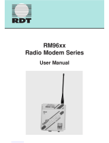
Multiple different product variants available, with housing, different antenna connector types,
voltage range, interface type etc. To compose the correct product order code, separate
Configuration Tool in the product WEB site.

SATELLINE-M3-TR1/ SATELLINE-M3-TR1 869
User Guide, Version 5.5
12
Picture, SATEL TR1 ConfigurationTool.

SATELLINE-M3-TR1/ SATELLINE-M3-TR1 869
User Guide, Version 5.5
13
1 SATELLINE-M3-TR1 TECHNICAL SPECIFICATIONS
RADIO
RECEIVER
TRANSMITTER
Frequency Range
330…420 Note*) / 403...473 MHz (Tuning range 90 / 70 MHz)
Channel Spacing
12.5 kHz / 20 kHz / 25 kHz programmable
Communication Mode
Half-Duplex
Frequency Stability
<1 kHz
Modulation
4-FSK, GMSK
Radio Compatibility
SATELLINE-3AS, Pacific Crest FST/4-FSK/GMSK, TRIMTALK450s
Spurious Radiation
< 2 nW
EN 300 113 and CFR47 part90
Sensitivity
-114 dBm @12.5 kHz
-111 dBm @25 kHz Note**) ***)
Co-channel Rejection
>-12 dB Note**)
Adjacent Channel Selectivity
> 47 dB @12.5 kHz
> 52 dB @ 25 kHz Note**)
Intermodulation Attenuation
> 60 dB Note**)
Blocking
> 86 dB Note**)
Spurious Rejection
> 60 dB Note**)
Spurious Emission
< -100 dBm
<-80 dBm on 3rd harmonic
@1215–1240 MHz
Type of Emission
F1D
Carrier power
100, 200, 500, 1000 mW
Adjacent Channel Power
EN 300 113 and CRF47 part90
Carrier power stability
< ±1.5 dB
DATA MODEM
Electrical Interface
Port 1:RS-232 / Port 2: LVTTL, TTL or RS-232/422 (depends on the assembly)
Interface Connector
D-15 (female)
Data speed of Serial interface
300 – 38400 bps
Data speed of Radio Interface
19200 bps (25 kHz channel) / 9600 bps (12.5 or 20 kHz channel)
GENERAL
Operating voltages
+6 …+30 VDC or +3 …+9 VDC (depending on the assembly)
Power Consumption
<1.2 W (Receive), <3.0 W (Transmit @ 0.5 W), <7.0 W (Transmit @ 1 W),
0.12 W (Sleep mode), 10 mW (DTR Power save)
Temperature Ranges
-25 °C ... +55 °C Complies with standards
-30 °C ... +65 °C Functional
-40 °C ... +75 °C Absolute min./max.
-40 °C ... +85 °C Storage
Antenna Connector
TNC female 50 ohm
Construction
Aluminium housing or without housing
Size L x W x T
129 x 63.5 x 23 mm (+/- 1 mm) or 89 x 49 x 9 mm
Weight
250 g or 50 g
COMPLIANT WITH THE INTERNATIONAL STANDARDS
RF-requirements
EN 300 113-2 / FCC CFR47 section 90
EMC-requirements
EN 301 489-1 & -5 (8 kV contact, 15 kV air discharge)
Safety Standard
EN 60950-1
Immunity
EN 61000-4-3 (2006) (10V/m)
Note*) 330.000 – 389.950 MHz, 390.050 – 420.000 MHz
Note**) Values apply with FEC ON @ BER<10E-3
Note***) Due to radio electronic design, the receiver is about 6 – 15 dB less sensitive on the
following frequencies:
403.000, 416.000, 429.000, 442.000, 455.000, 468.000, 409.5875 and 469.200 MHz.

SATELLINE-M3-TR1/ SATELLINE-M3-TR1 869
User Guide, Version 5.5
14
2 SATELLINE-M3-TR1 869 TECHNICAL SPECIFICATIONS
RADIO
RECEIVER
TRANSMITTER
Frequency Range
869.4125 – 869.6375 MHz
865 – 867 MHz (for India)
Channel Spacing
25 kHz
Communication Mode
Half-Duplex
Frequency Stability
<1 kHz
Modulation
4-FSK
Radio Compatibility
SATELLINE-3AS 869
Spurious Radiation
< 2 nW
according to EN 300 220
Sensitivity (BER < 10 E-3)
-111dBm Note*)
Co-channel Rejection
>-12 dB Note*)
Adjacent Channel Selectivity
> 52 dB Note*)
Intermodulation Attenuation
>60 dB Note*)
Blocking
>86 dB Note*)
Spurious Rejection
>60 dB Note*)
Type of Emission
F1D
Carrier power
10, 20, 50, 100, 200, 500 mW
Adjacent Channel Power
according to EN 300 220
Carrier power stability
< ±1.5 dB
DATA MODEM
Electrical Interface
Port1: RS-232 / Port2: LVTTL, TTL or RS-232 /422 (depends on the
assembly)
Interface
Connector
D-15 female
Data speed of Serial
interface
300 – 38400 bps
Data speed of Radio
Interface
19200 bps (25 kHz channel)
GENERAL
Operating voltages
+6 … +30 VDC
Power Consumption
<1.2 W (Receive), <3.8 W (Transmit)
0.12 W (Sleep mode), 10 mW (DTR Power save)
Temperature Ranges
-25 °C ... +55 °C Complies with standards
-30 °C ... +65 °C Functional
-40 °C ... +75 °C Absolute min./max.
-40 °C ... +85 °C Storage
Antenna Connector
TNC female 50 ohm
Construction
Aluminium housing or without housing
Size H x W x D
129 x 63.5 x 23 mm (+/- 1 mm) or 89 x 49 x 9 mm
Weight
250 g or 50 g
COMPLIANT WITH THE INTERNATIONAL STANDARDS
RF-requirements
EN 300 220-2
EMC-requirements
EN 301 489-1 & -3 (8 kV contact, 15 kV air discharge)
Safety Standard
EN 60950-1
Immunity
EN 61000-4-3 (2006) (10V/m)
Note*) Values apply with FEC ON @ BER<10E-3

SATELLINE-M3-TR1/ SATELLINE-M3-TR1 869
User Guide, Version 5.5
15
2.1 Important note for the users of SATELLINE-M3-TR1 869
NOTE!
SATELLINE-M3-TR1 869 does NOT support all features of SATELLINE-M3-TR1
Please note that the paragraphs of this user guide describing the features listed below apply
only to SATELLINE-M3-TR1 unless specifically mentioned.
Feature/Property
SATELLINE-M3-TR1 869
SATELLINE-M3-TR1
Frequency band
869.4125...869.6375 MHz
330 … 420 / 403…473 MHz
Channel spacing/width
25 kHz fixed
25, 20, 12.5 kHz
Transmitter output
10, 20, 50, 100, 200, 500 mW
100, 200, 500, 1000 mW
Supported radio
compatibility options
SATELLINE-3AS
SATELLINE-3AS
PacCrest-4FSK
PacCrest-GMSK
Trimtalk450s
PacCrest-FST
Free Channel Scan (FCS)
Not supported
Supported
Channel list
Not supported
Supported
Call sign transmission
Not supported
Supported
Radio requirements
specification
(see the previous pages)
EN 300 220-2
EN 300 113-2
FCC CFR47 section 90
Operating voltage
+6…+30 V
DC
+6…+30 V
DC
+3…+9 V
DC
2.2 Sub-band Channel Assignment – SATELLINE-M3-TR1 869
2.2.1 Sub-band
Each sub-band is defined by a start and stop frequency. Furthermore the maximum allowed
power level and maximum duty cycle is defined separately for each sub-band.
2.2.2 Duty cycle
The purpose of the duty cycle limit is to ensure that no single application can occupy this license-
free band for more than a certain percentage of time. The term duty cycle defines the percentage
of a 1-hour period a single modem is allowed to transmit. The modem limits the duty cycle itself.
Duty cycle is limited by the firmware by adapting to the transmitted data. The absolute maximum for
a transmission is 1 second after which the transmitter is switched off.

SATELLINE-M3-TR1/ SATELLINE-M3-TR1 869
User Guide, Version 5.5
16
2.2.3 Power level
The power level limit is defined separately for each sub-band. The maximum power limit for each
sub-band is pre-programmed into the SATELLINE-M3-TR8. The user can choose from 10, 20, 50,
100, 200 and 500 mW ERP* output power for frequency variant 868…870 MHz and for Indian
frequency variant 865…867 MHz following power levels: 10, 20, 50, 100, 200, 500 and 1000 mW
ERP*. No matter what power level the user has chosen the maximum allowed power level of the
chosen sub-band cannot be exceeded.
*ERP = The effective radiated power from the antenna relative to a half-wave dipole in a certain
direction.
2.2.4 Channel assignment
Each sub-band is divided into 25 kHz channels according to a channel assignment scheme defined
by the recommendation CEPT/ERC/REC 70-03.
The subband settings for EASy 869 and TR1 869 (868…870 MHz versions) are by default:
Active subband: Subband1
Subband1: 869.4000 – 869.6500 MHz, 500 mW, 10 % duty cycle
Subband2: 869.6500 – 869.7000 MHz, 25 mW, 10 % duty cycle
Subband3: 869.7000 – 870.0000 MHz, 25 mW, 1 % duty cycle
Subband4: 869.7000 – 870.0000 MHz, 5 mW, 100 % duty cycle
When the user selects the active subband, RX/TX frequencies will also switch to Subband Min
Freq+12.5 kHz (for example 869.4125 MHz for Subband1).
Note. The active subband can be selected by using SL command SL&B= or selecting on the
programming menu. SATEL Configuration Manager (current version 1.4.5) does not support the
subband settings yet.
CTS line indicates the duty cycle. Any transmitted data appearing at the serial port outside the
duty cycle period is ignored.

SATELLINE-M3-TR1/ SATELLINE-M3-TR1 869
User Guide, Version 5.5
17
3 INTERFACE – CONNECTORS & LEDS
3.1 Antenna connector
SATELLINE-M3-TR1 and SATELLINE-M3-TR1 869 have a HIROSE compatible 50 Ohm U.FL male
antenna connector on the printed circuit board with impedance of 50 Ohm.
An external antenna is connected typically by using a female U.FL to TNC, MCX, MMCX or SMA
pigtail adapter. In case the antenna load is not 50 Ohm, the impedance matching should be
placed in the host application.
The antenna should always be connected when the power is on. Removing the antenna while
the transmitter is on may damage the power amplifier inside the transmitter.
3.2 Power supply
SATELLINE-M3-TR1 is available in two operating voltage ranges depending on which type of
internal power/interface-module has been installed at the factory. The voltage range is marked
on the label:
• +6…+30 V
DC
(delivered by default)
• +3…+9 V
DC
SATELLINE-M3-TR1 869 is currently available only in +6…+30 V
DC
operating voltage range.
The radio modem must be connected to a power supply with an adequate current output.
A proper fuse should be connected in between the radio modem and the power supply:
Operating voltage range
+3 … +9 V
+6 … +30 V
Current rating of the fuse
2.5 A slow
1 A slow
Operating voltage range of SATELLINE-M3-TR1 is marked as follows:

SATELLINE-M3-TR1/ SATELLINE-M3-TR1 869
User Guide, Version 5.5
18
3.3 Serial ports
Before connecting DTE (Data Terminal Equipment) to the radio modem, please make sure that
the configuration matches the physical interface (electrical characteristics, timing, direction and
interpretation of signals). The radio modem contains two separate serial ports that are
designated as Port 1 and Port 2. Only one port at a time can be selected for communication.
Port 1 - Always RS-232 (Port 1 ON is the default configuration)
Port 2 – The physical interface depends on which type of internal power/interface-module has
been installed at the factory. Available options are:
• RS-232/RS-422 (delivered by default)
• LVTTL
• TTL
RS-422 interface of the radio modem can be adapted to RS-485 interface by wiring the signals
externally, see paragraph RS-485 interface.
3.4 LED indicators
There are two LED indicators on the printed circuit board that indicate the status of the serial
port and the radio interface:
LED
Indication
OFF
Red
Red flashing
Green
Power
Power indicator
Power OFF or
Sleep
-
-
Power ON
RX/TX
Data/Mode indicator
Idle
Programming
mode
Data transfer active
-
NOTE! WHEN THE MODE-PIN IS CONNECTED TO GROUND, THE RADIO MODEM IS IN THE
PROGRAMMING MODE AND Port 1 IS THEN IN USE!
If Port 2 is to be used for data transmission, the serial cable must be changed to a suitable
type when switching over to the programming mode.

SATELLINE-M3-TR1/ SATELLINE-M3-TR1 869
User Guide, Version 5.5
19
3.5 26-pin micro header connector
Terminal equipment is connected to the 26-pin micro header connector (pitch 1.27 mm). There
are two types of the connector available depending on the assembly:
26-pin MALE connector: Part type Samtec FTSH-113-04-L-DV-A-P-TR (top view)
26-pin FEMALE connector: Part type: Weitronic 613-26-20-10-2-10 (side view)
SATELLINE-M3-TR1 radio modem modules: 26-PIN CONNECTOR PINOUT
I/O column below denotes the direction of the signal: "IN" is from DTE (Data Terminal
Equipment) to the radio modem. "OUT" is from the radio modem to DTE.
PIN
NAME
I/O
LEVEL
EXPLANATION
1
2
3
4
V
b
-
Power
Operating Voltage. Depends on the assembled power module:
+3...9 VDC (Only for SATELLINE-M3-TR1) / +6...30 VDC
5
RTS
IN
RS-232
Request To Send from DTE. Note*)
6
MODE
IN
0..30V
<2VDC or connected to ground = Programming Mode
>3VDC or Not connected = Data Transfer Mode Note**)
7
TD1
IN
RS-232
Port1 Transmit Data from DTE to the radio modem.
8
DSR
OUT
RS-232
Data Set Ready. Indicates that the radio modem is ON.
9
RD1
OUT
RS-232
Port1 Receive Data to DTE from the radio modem
10
BOOT
IN
0…5V
Boot flash enable (only for factory use)
11
SPARE1
-
Reserved for future purposes
12
SPARE2
-
Reserved for future purposes
13
CD_TTL
OUT
TTL
Carrier Detect (in case power/interface-module is TTL)
LVTTL
Carrier Detect (in case power/interface-module is LVTTL)
1
13
14
26

SATELLINE-M3-TR1/ SATELLINE-M3-TR1 869
User Guide, Version 5.5
20
14
GPIN
IN
General purpose input for specific purposes
15
GPOUT
OUT
General purpose output for specific purposes
16
CD_RS
OUT
RS-232
Reserved for future purposes
17
DTR
IN
0..30V
Data Terminal Ready. The pin can be used to wake-up the
radio module from the standby mode. >+3 VDC or not
connected = ON, <+0.6 VDC = STANDBY
18
Pin 18 has alternative functions depending on the Port2 configuration, see below.
CD
OUT
RS-232
Carrier Detect (if Port2 Interface level is RS-232)
A’
OUT
RS-422
Port2 Receive Data positive (if Port2 Interface level is RS-422)
CTS
OUT
TTL
Clear To Send Note*) (if Port2 Interface level is TTL)
LVTTL
Clear To Send Note*) (if Port2 Interface level is LVTTL)
19
Pin 19 has alternative functions depending on the Port2 configuration, see below.
RD2
OUT
OUT
OUT
RS-232
Port2 Receive Data (if Port2 Interface level is RS-232)
TTL
Port2 Receive Data (if Port2 Interface level is TTL)
LVTTL
Port2 Receive Data (if Port2 Interface level is LVTTL)
B’
OUT
RS-422
Port2 Receive Data negative (if Port2 Interface level is RS-422)
20
Pin 20 has alternative functions depending on the configuration, see below.
TD2
IN
IN
IN
RS-232
Port2 Transmit Data (if Port2 Interface level is RS-232)
TTL
Port2 Transmit Data (if Port2 Interface level is TTL)
LVTTL
Port2 Transmit Data (if Port2 Interface level is LVTTL)
A
IN
RS-422
Port2 Transmit Data positive (if Port2 Interface level is RS-422)
21
Pin 21 has alternative functions depending on the hardware assembly, see below.
RTS
IN
TTL
Request To Send Note*) (if Port2 Interface level is TTL)
LVTTL
Request To Send Note*) (if Port2 Interface level is LVTTL)
B
IN
RS-422
Port2 Transmit data negative
22
CTS
OUT
RS-232
Clear To Send. This signal indicates that the radio modem
serial interface is ready to receive data from DTE. Note*)
23,
24,
25,
26
GND
-
Operating voltage ground / signal ground.
Galvanically connected to the modem casing.
Note! Unused pins can be left unconnected.
Note*) RTS and CTS signals apply to the selected Data port (either Port1 or Port2).
Note**) Programming Mode is for changing the settings of the radio modem via Programming
menu. Normally the MODE line is NOT connected i.e. the modem is in Data Transfer Mode.
/