Page is loading ...

SATEL Proof-TR4/-TR9
User Guide, Version 1.0
1
SATEL Proof-TR4/-TR9
Radio Modem
User Guide

SATEL Proof-TR4/-TR9
User Guide, Version 1.0
2
TABLE OF CONTENTS
TABLE OF CONTENTS ........................................................................................ 2
IMPORTANT NOTICE ......................................................................................... 4
RESTRICTIONS ON USE – SATEL PROOF-TR4 .................................................... 5
RESTRICTIONS ON USE – SATEL PROOF-TR9 .................................................... 6
PRODUCT CONFORMITY .................................................................................... 7
WARRANTY AND SAFETY INSTRUCTIONS ......................................................... 8
GROUNDING .................................................................................................... 9
1 DESCRIPTION OF THE PRODUCT ................................................................ 10
2 SATEL PROOF-TR4/-TR9 TECHNICAL SPECIFICATIONS .............................. 11
3 CONFIGURATION ...................................................................................... 14
3.1 Configuration ....................................................................................... 14
3.1.1 Configuration Manager .............................................................................................. 14
3.1.2 Changing parameters using the SL COMMANDS .......................................................... 15
4 MODEM SETTINGS ..................................................................................... 16
4.1 Default settings of SATEL Proof-TR4 .................................................... 16
4.2 Default settings of SATEL Proof-TR9 .................................................... 17
5 ANTENNA CONNECTOR ............................................................................. 19
6 DEUTSCH CONNECTOR .............................................................................. 20
Power supply ................................................................................................... 20
7 SERIAL PORTS............................................................................................. 21
7.1 Pause length ........................................................................................ 21
7.2 Data buffering ...................................................................................... 22
8 RF INTERFACE - SATEL PROOF-TR4 ............................................................ 23

SATEL Proof-TR4/-TR9
User Guide, Version 1.0
3
8.1 Transmitter ........................................................................................... 24
8.2 Receiver ................................................................................................ 25
8.3 Priority RX/TX ....................................................................................... 25
8.4 Forward Error Correction (FEC) ............................................................ 26
8.5 Error checking ...................................................................................... 26
8.6 TX delay................................................................................................ 26
8.7 Separate RX/TX-frequencies ................................................................ 26
8.8 Pacific Crest and TRIMTALK compatibility ............................................ 27
8.8.1 Settings in compatibility modes .................................................................................... 27
8.8.2 Repeater function....................................................................................................... 29
8.8.3 Support for Local / Remote addresses .......................................................................... 29
8.8.4 Transmission delays ................................................................................................... 30
9 MECHANICAL DIMENSIONS ....................................................................... 32
10 INSTALLATION ........................................................................................... 33
11 ACCESSORIES ............................................................................................. 34

SATEL Proof-TR4/-TR9
User Guide, Version 1.0
4
IMPORTANT NOTICE
All rights to this manual are owned solely by SATEL Oy (referred to in this user guide as SATEL).
All rights reserved. The copying of this manual (without the written permission from the owner) by
printing, copying, recording or by any other means, or the full or partial translation of the
manual to any other language, including all programming languages, using any electrical,
mechanical, magnetic, optical, manual or other methods or devices is forbidden.
SATEL reserves the right to change the technical specifications or functions of its products, or to
discontinue the manufacture of any of its products or to discontinue the support of any of its
products, without any written announcement and urges its customers to ensure, that the
information at their disposal is valid.
SATEL software and programs are delivered ”as is”. The manufacturer does not grant any kind
of warranty including guarantees on suitability and applicability to a certain application. Under
no circumstances is the manufacturer or the developer of a program responsible for any
possible damages caused by the use of a program. The names of the programs as well as all
copyrights relating to the programs are the sole property of SATEL. Any transfer, licensing to a
third party, leasing, renting, transportation, copying, editing, translating, modifying into another
programming language or reverse engineering for any intent is forbidden without the written
consent of SATEL.
SATEL PRODUCTS HAVE NOT BEEN DESIGNED, INTENDED NOR INSPECTED TO BE USED
IN ANY LIFE SUPPORT RELATED DEVICE OR SYSTEM RELATED FUNCTION NOR AS A PART
OF ANY OTHER CRITICAL SYSTEM AND ARE GRANTED NO FUNCTIONAL WARRANTY IF
THEY ARE USED IN ANY OF THE APPLICATIONS MENTIONED.
Salo, FINLAND 2019
Copyright: 2019 SATEL Oy
No part of this document may be reproduced, transmitted or stored in a retrieval system in any
form or by any means without the prior written permission of SATEL Oy. This document is
provided in confidence and must not be distributed to third parties without the express
permission of SATEL Oy.

SATEL Proof-TR4/-TR9
User Guide, Version 1.0
5
RESTRICTIONS ON USE – SATEL Proof-TR4
SATEL Proof-TR4 radio transceiver module has been designed to operate on 403-473 MHz, the
exact use of which differs from one region and/or country to another. The user of a radio
transceiver module must take care that the said device is not operated without the permission of
the local authorities on frequencies other than those specifically reserved and intended for use
without a specific permit.
SATEL Proof-TR4 is allowed to be used in the following countries, either on license free channels
or on channels where the operation requires a license. More detailed information is available at
the local frequency management authority.
Countries: AE, AT, AU, BE, BG, BR, CA, CH, CY, CZ, DE, DK, EE, ES, FI, FR, GB, GR, HU, HR,
IE, IS, IT, JP, KR, LT, LU, LV, MT, NL, NO, PL, PT, RU, RO, SE, SI, SK, TR, US
WARNING! Users of SATEL Proof-TR4 radio transceiver modules in North America should be aware, that
due to the allocation of the frequency band 406.0 – 406.1 MHz for government use only, the use of radio
transceiver module on this frequency band without a proper permit is strictly forbidden.
WARNING - RF Exposure
To comply with CE, FCC and IC RF exposure compliance requirements,
maximum antenna gain is 14 dBi and separation distance of at least 1 meter
must be maintained between the antenna of this device and all persons. This
device must not be co-located or operating in conjunction with any other
antenna or transmitter.

SATEL Proof-TR4/-TR9
User Guide, Version 1.0
6
RESTRICTIONS ON USE – SATEL Proof-TR9
SATEL Proof-TR9 radio transceiver module has been designed to operate on 902-928 MHz, the
exact use of which differs from one region and/or country to another. The user of a radio
transceiver module must take care that the said device is not operated without the permission of
the local authorities on frequencies other than those specifically reserved and intended for use
without a specific permit.
SATEL Proof-TR9 is allowed to be used in the following countries. More detailed information is
available at the local frequency management authority.
Countries: AU, CA and US.
This radio transmitter 2422A-SATELTA31 has been approved by Industry Canada to operate with
the antenna types listed below with the maximum permissible gain indicated. Antenna types not
included in this list, having a gain greater than the maximum gain indicated for that type, are
strictly prohibited for use with this device.
Antenna type
Manufacturer
Antenna model
Maximum gain (dBi)
Omnidirectional
Oy CompleTech Ltd
CA915H
5
Directional (yagi)
Oy CompleTech Ltd
CA930Y
6
NOTE!
According to the requirements of the FCC, the integrator should make sure that the SATEL
Proof-TR9 is compliant to part 15C while integrated in the host device. Output power and
spurious emissions should be verified.
WARNING - RF Exposure
To satisfy FCC and ISED RF exposure requirements for mobile transmitting devices, a
separation distance of 25 cm or more should be maintained between antenna of this device
and persons during device operation. To ensure compliance, operations at closer than this
distance is not recommended. The antenna used for this transmitter must not be co-located in
conjunction with any other antenna or transmitter. FCC regulations allow up to 36 dBm
equivalent isotropically radiated power (EIRP). Therefore, the sum of the transmitted power (in
dBm), the cabling loss and the antenna gain cannot exceed 36 dBm.

SATEL Proof-TR4/-TR9
User Guide, Version 1.0
7
PRODUCT CONFORMITY
Hereby, SATEL Oy declares that radio modems are in compliance with the essential
requirements (radio performance, electromagnetic compatibility and electrical safety) and other
relevant provisions of Directive 2014/53/EU. Therefore the equipment is labelled with CE-
marking.

SATEL Proof-TR4/-TR9
User Guide, Version 1.0
8
WARRANTY AND SAFETY INSTRUCTIONS
Read these safety instructions carefully before using the product:
-Warranty will be void, if the product is used in any way that is in contradiction with the
instructions given in this manual, or if the radio modem housing has been opened or tampered
with.
-The radio modem is only to be operated at frequencies allocated by local authorities, and
without exceeding the given maximum allowed output power ratings. SATEL and its distributors
are not responsible, if any products manufactured by it are used in unlawful ways.
-The devices mentioned in this manual are to be used only according to the instructions
described in this manual. Faultless and safe operation of the devices can be guaranteed only if
the transport, storage, operation and handling of the devices is appropriate. This also applies to
the maintenance of the products.
-To prevent damage both the radio modem and any terminal devices must always be switched
OFF before connecting or disconnecting the serial connection cable. It should be ascertained
that different devices used have the same ground potential. Before connecting any power cables
the output voltage of the power supply should be checked.
- Any radio link can susceptible to external interference and signal degradation by its nature.
Because of that, the effects of possible interference mechanism and the sufficient back-up
schemes must be taken into account in the system design of the critical applications.
NOTE!
When selecting a suitable location for the radio modem it must be ensured that no water can
get into the radio modem under any conditions. Direct sunlight is also to be avoided. It is not
recommendable to install the radio modem on a strongly vibrating surface. Suitable
dampening and/or isolation materials should be used in cases where the installation surface
will be subjected to vibration.

SATEL Proof-TR4/-TR9
User Guide, Version 1.0
9
GROUNDING
SATEL Proof-TR4 / -TR9 is equipped with a grounding terminal, as shown below. It is
recommended to connect a ground wire from the grounding terminal to the earth ground and
that all other interconnected devices share the same electrical ground potential.
Besides the mains voltage safety, proper grounding is essential also for the error free operation
of radio links and the protection against over-voltages and lightning. Although SATEL Proof-TR4
/ -TR incorporates a robust internal surge protection, the surge spikes and power transients
caused by lightning, ESD or other electrical systems must be discharged to earth ground.
General installation guidelines for grounding:
Perform grounding of the system in accordance with local and national regulations.
Check the grounding related information of other products in the system.
Use short low impedance cables. Although DC resistance of a ground cable may be a
fraction of an ohm, its impedance may be thousands of ohms on the radio frequency.
Wide copper straps are the best.
The ground connection should be connected directly to the power supply, not the ground
connection of the load, in order to isolate the radio from voltage drops across the
ground return for the load.
Equipment of the radio system should be grounded in a star ground configuration. The
center of the star should be usually connected directly to a good external earth ground
scheme.
The mast installations require special measures in the construction of ground electrodes
and equipotential bonding – consult professional installation providers.

SATEL Proof-TR4/-TR9
User Guide, Version 1.0
10
1 DESCRIPTION OF THE PRODUCT
SATEL Proof-TR4/-TR9 is a UHF radio transceiver modem. It provides a transparent data link
with other SATELLINE- family modems (SATELLINE-EASy, -TR1, -TR3, -TR4, -R3, -TR9, -EASy Pro,
-4Pro, SATEL Compact-Proof and EASy-Proof). SATEL Proof-TR4/-TR9 can be interconnected to
a data terminal or similar devices by RS-232.
SATEL Proof-TR4/-TR9 contains a 6 pin Deutsch DT connector for RS-232 and power supply, and
TNC female connector for antenna.
SATEL Proof-TR4/-TR9 is intended to be used inside or outside environment and fulfills IP69K
ratings (high pressure hot water). See more detailed description on chapter “Technical
Specifications”.
Available models and product codes:
- YM6583 SATEL Proof-TR4 with AES128 encryption support
- YM6584 SATEL Proof-TR4 without AES128 encryption support
- YM6587 SATEL Proof-TR9

SATEL Proof-TR4/-TR9
User Guide, Version 1.0
11
2 SATEL Proof-TR4/-TR9 TECHNICAL SPECIFICATIONS
SATEL Proof-TR4 complies with the following international standards:
o EN 300 113
o EN 300 489 (EMC)
o IEC 60950 (safety)
o FCC CFR47 part90
RECEIVER
TRANSMITTER
Note!
Frequency Range
403 ... 473 MHz
Tuning range
70 MHz
Minimum RF Frequency
Step
6.25 kHz
Channel Bandwidth
12.5 kHz / 25 kHz
Programmable
Frequency Stability
<1 kHz
Maximum Receiver Input
Power without Damage
+14 dBm
Maximum Receiver Input
Power without
Transmission Errors
-10 dBm
FEC ON
Sensitivity
-111 dBm @ 25 kHz
-117 dBm @12.5 kHz
FEC ON
Blocking
> 86 dB @ 25 kHz
> 88 dB @ 12.5 kHz
FEC ON
Intermodulation
Attenuation
> 61 dB @ 25 kHz
> 61 @ 12.5 kHz
FEC ON
CO-Channel Rejection
> -11 dB @ 25 kHz
> -10 dB @ 12.5 kHz
FEC ON
Adjacent Channel
Selectivity
> 56 dB @ 25 kHz
> 51 dB @ 12.5 kHz
FEC ON
Spurious Rejection
> 67 dB
FEC ON
Typical Power
Consumption
RX
12 V: 1.32 W
TX
12 V: 5.8 W @ 1 W RF
Transmitter Power
(programmable)
0.1, 0.2, 0.5, 1 W
TX-mode, 50Ω load
Communication Mode
Half-Duplex
Adjacent Channel Power
acc. to EN 300 113
TX-mode
Transient Adjacent
Channel Power
acc. to EN 300 113
TX-mode
Carrier power stability
< ±1.5 dB

SATEL Proof-TR4/-TR9
User Guide, Version 1.0
12
DATA MODEM
Note
Electrical Interface
RS-232
Data speed of Serial
Interface
1200 – 115200 bps
Data speed of Radio
Interface
4FSK FEC OFF: 19200 bps (25 kHz) 9600 bps (12.5 kHz)
4FSK FEC ON: 14400 bps (25 kHz) 7200 bps (12.5 kHz)
8FSK FEC OFF: 28800 bps (25 kHz) 14400 bps (12.5 kHz)
8FSK FEC ON: 19200 bps (25 kHz) 9600 bps (12.5 kHz)
16FSK FEC ON: 28800 bps (25 kHz) 14400 bps (12.5 kHz)
Data Formats
Asynchronous data
Air Interface Encryption
AES128
Programmable
Modulation
4FSK, 8FSK, 16FSK, GMSK
Values are subject to change without a notice.

SATEL Proof-TR4/-TR9
User Guide, Version 1.0
13
SATEL Proof-TR9 complies with the following international standards:
FCC Parts 15.209 and 15.247 of Title 47
IC RSS-247, ICC RSS-Gen
AS/NZS 4268:2012, AS/NZS 4771:2000
RECEIVER
TRANSMITTER
Frequency Range
902-928 MHz
Spreading Method
Frequency Hopping
Occupied Bandwidth
230 kHz
Frequency Stability
<1 kHz
Maximum Receiver Input Power
without Transmission Errors
-3 dBm
Sensitivity
typ. -109 dBm for BER 10
-4
Transmitter Power
0.01, 0.02, 0.5, 0.1, 0.2, 0.5, 1 W
Carrier power stability
< ±1.5 dB
Electrical Interface
RS-232
Data Speed of Radio Interface
115200 bps
Modulation Method
2-GFSK
Hopping Bands
7, user selectable
Hopping Patterns
15 per band, 105 total, user selectable
Hopping Channels
50-112, user selectable
Frequency Zones
16 Zones, 7 Channels per Zone
Data speed of Serial interface
9600 – 115200 bps
GENERAL FOR BOTH TR4 and TR9
Note
Operating Voltage
+6 … +30 Vdc +/- 10% Vdc
External DC supply
Temperature
Ranges
-30 °C ... +65 °C
Operational
-40 °C … +75 C
Absolute min / max
-25 °C ... +55 °C
Complies with
standards
-40 °C … +85 C
Storage
Antenna Connector
50 , TNC female
Interface Connector
Deutsch DT04-6P-CL09
Housing
Shielded / bare PCB inside a metal housing
Size L x W x H
176 x 95 x 42 mm
IP rating
IP69K
high pressure
Mechanical
Properties
IEC60068-2-32, ISO9022-36-08, ISO9022-31-06,
ISO9022-33-06
Weight
<500 g
OTHER MEASURES
Note
ESD-failure
threshold
8 kV contact, 15 kV air discharge
Immunity test
10 V/m
Values are subject to change without a notice.

SATEL Proof-TR4/-TR9
User Guide, Version 1.0
14
3 CONFIGURATION
3.1 Configuration
The configuration of SATEL Proof–TR4/-TR9 radio modem can be modified by connecting the
modem to the PC and using SATEL Configuration Manager (CM) or by using external SL
commands. Programming is done using RS-232 port. The RS-232 serial port settings must match
between SATEL Proof–TR4/-TR9 and terminal port. Download the supporting software from
https://www.satel.com/support-and-services/downloads/
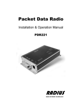
3.1.1 Configuration Manager
Configuration manager program makes it possible to edit the modem settings and update the
firmware.
QuickStart
Preliminary settings:
1. Save the SATEL Configuration Manager files in the same
directory.
2. Connect the modem to the PC using a proper interface
cable.
3. Connect power to the modem. Before connecting, check
that you have correct supply voltage.
4. Open the SATEL Configuration Manager program. Check from the “Program Preferences”
tab, that you have selected correct COM-port number and that the serial port settings match
to the modem. Default settings are 115200 bps, 8 bit, no parity, 1 stop bit.
5. To establish connection between the modem and the PC, click the blue Connect tab. To get
the radio modem info, click blue Read Settings tab.
6. Check the settings and modify if needed.
7. Store settings to a modem using “Write settings” –button.
More information about Configuration Manager can be found from user guide.

SATEL Proof-TR4/-TR9
User Guide, Version 1.0
15
3.1.2 Changing parameters using the SL COMMANDS
The controlling terminal device can change the configuration settings of a radio modem. This is
accomplished with the help of SL commands, which can be used during data transfer. SL
commands can be used to change e.g. the frequency or addresses. It is also possible to
interrogate a radio modem in order to gain information concerning current settings that are in
use. The terminal device is either a PC or a programmable logic (PLC) together with suitable
(terminal) program. SL commands must be enabled using Programming Mode before they can
be used.
An SL command is a one continuous string of characters, which is separated from other data by
pauses that are equal or greater than time defined by Pause length parameter in the set-up. No
extra characters are allowed at the end of an SL command.
The radio modem will acknowledge all commands by returning an "OK" (command carried out
or accepted) or the requested value, or an "ERROR" (command not carried out or interpreted as
erroneous) message.
In case you need more information on the time delays related to the use of SL commands,
please contact the manufacturer.
SL commands are described in separate documentation.
In order to get information of the latest and/or special SL commands please contact SATEL.

SATEL Proof-TR4/-TR9
User Guide, Version 1.0
16
4 MODEM SETTINGS
4.1 Default settings of SATEL Proof-TR4
The radio modem is delivered with the following default settings (unless otherwise specifically
ordered):
DEFAULT VALUES OF THE ADJUSTABLE SETTINGS ( the user can change these settings later on )
Setting
Default value
Range
Radio frequency
Operating TX frequency
438.000 MHz
Range: 403-473 MHz
Operating RX frequency
438.000 MHz
Range: 403-473 MHz
Reference Frequency
438.000 MHz
Range: 403-473 MHz
Channel Spacing
25 kHz
Range: 12.5 kHz or 25 kHz
Radio settings
TX Power
1000 mW
Range: 100, 200, 500 or 1000 mW
Signal threshold
-115 dBm
- 80 … -118 dBm
TX-Start Delay
0 ms
0-65535 ms
Radio Compatibility
(Available set depends on
the factory configuration)
SATELLINE 3AS
SATELLINE 3AS
PacCrest-4FSK
PacCrest-GMSK
TrimTalk450s(P)
TrimTalk450s(T)
PacCrest-FST
SATEL 8FSK-1
SATEL 8FSK-2
SATEL 16FSK-1
Addressing
RX Address
OFF
ON/OFF
TX Address
OFF
ON/OFF
Serial port
Data speed
115200 bps
1200 – 115200 bps
Data bits
8
8
Parity bits
None
None, Even, Odd.
Stop bits
1
1

SATEL Proof-TR4/-TR9
User Guide, Version 1.0
17
Handshaking
Handshaking lines apply to the DATA-port.
Pause length
3 bytes
3….255
Additional setup
Error correction, FEC
OFF
ON/OFF
Error check
OFF
OFF, CRC8Partial, CRC8Full, CRC16Full
Repeater Mode
OFF
ON/OFF
SL-commands
ON
ON/OFF
TX Delay
0
0 …. 65535 ms
Over-the-Air-Encryption
OFF
ON/OFF
Use Channel List
OFF
ON/OFF
Power Save Mode
OFF
ON/OFF
Add RSSI to Data
OFF
ON/OFF
4.2 Default settings of SATEL Proof-TR9
The radio modem is delivered with the following default settings (unless otherwise specifically
ordered):
DEFAULT VALUES OF THE ADJUSTABLE SETTINGS (the user can change these settings later on)
Operation Mode
Default value
Note
Point-to-Multipoint Slave
3
Set Baud Rate
Baud Rate
115200
Data Parity
0
Modbus RTU
0
RS232/485
0
Setup Port
3
TurnOffDelay/OnDelay
0/0
FlowControl
0
Radio Parameters
FreqKey
5
Hop Table Version
0
Hop Table Size
112
Hop Freq Offset
0
Frequency Zone
All 1s (Enabled)
Max Packet Size
8
Min Packet Size
9
Xmit Rate
1
RF Date Rate
3
RF Xmit Power
1000
Slave Security
0
RTS to CTS
0
Retry Timeout
255
Low Power Mode
0

SATEL Proof-TR4/-TR9
User Guide, Version 1.0
18
High Noise
0
MCU Speed
0
Remote LED
0
Multipoint Parameters
Number of Repeaters
1
Master Packet Repeat
3
Max Slave Retry
9
Retry Odds
9
DTR Connect
0
Repeater Frequency
0
Network ID
255
Multimaster Sync
0
Slave/Repeater
0
Subnet ID
“Disabled”

SATEL Proof-TR4/-TR9
User Guide, Version 1.0
19
5 ANTENNA CONNECTOR
All models have a single TNC female type antenna connector with impedance of 50 Ohm.
The antenna should always be connected when the power is on.

SATEL Proof-TR4/-TR9
User Guide, Version 1.0
20
6 DEUTSCH CONNECTOR
Note*) Power supply input should be used with a FUSE = 1A slow
Note**) Reserved for future needs.
Power supply
SATEL Proof-TR4/-TR9 is available in one operating voltage range. The radio modem must be
connected to a power supply with an adequate current output.
A proper fuse should be connected in between the radio modem and the power supply:
Operating voltage range
+6 … +30 V
Current rating of the fuse
1 A slow
pin
direction
Deutsch DT04-6P-CL09
1
input
+DC power supply*)
2
-
**)
3
-
**)
4
input
TD, Port 1
5
output
RD, Port 1
6
-
GND
/