Alpha PWE-SG Installation guide
- Category
- Electrical enclosures
- Type
- Installation guide
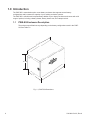
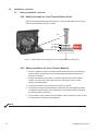
Alpha PWE-SG is a Pole Mount Battery Expansion Enclosure designed to expand the battery backup capacity of compatible Alpha power systems. It can be used in wooden or steel pole installations and features an optional battery heater mat to maintain battery performance in cold environments. The enclosure is equipped with a grounding lug for safety and has ample space for cable management. It also includes an optional tamper switch for added security.
Alpha PWE-SG is a Pole Mount Battery Expansion Enclosure designed to expand the battery backup capacity of compatible Alpha power systems. It can be used in wooden or steel pole installations and features an optional battery heater mat to maintain battery performance in cold environments. The enclosure is equipped with a grounding lug for safety and has ample space for cable management. It also includes an optional tamper switch for added security.


-
 1
1
-
 2
2
-
 3
3
-
 4
4
-
 5
5
-
 6
6
-
 7
7
-
 8
8
-
 9
9
-
 10
10
-
 11
11
-
 12
12
-
 13
13
-
 14
14
-
 15
15
-
 16
16
-
 17
17
-
 18
18
-
 19
19
-
 20
20
-
 21
21
-
 22
22
-
 23
23
-
 24
24
-
 25
25
-
 26
26
-
 27
27
-
 28
28


Alpha PWE-SG Installation guide
- Category
- Electrical enclosures
- Type
- Installation guide
Alpha PWE-SG is a Pole Mount Battery Expansion Enclosure designed to expand the battery backup capacity of compatible Alpha power systems. It can be used in wooden or steel pole installations and features an optional battery heater mat to maintain battery performance in cold environments. The enclosure is equipped with a grounding lug for safety and has ample space for cable management. It also includes an optional tamper switch for added security.
Ask a question and I''ll find the answer in the document
Finding information in a document is now easier with AI
Related papers
-
Alpha Northern PWE Series Installation guide
-
-
Alpha PWE Enclosure Installation guide
-
-
-
-
-
-
-
Alpha AlphaGuard Installation guide
Other documents
-
Del Hutson Designs DHD2002wln Operating instructions
-
Modine 78806 Installation guide
-
 ALPHACELL User manual
-
WarmlyYours SCV-DUAL Product information
-
Lightolier 7596 User manual
-
Kmart 43164219 User manual
-
Clinton Electronics CE-CMHL-EX User manual
-
Ergotron 60-591-003 Assembly Instructions
-
AFi ENC-1P Assembly Instructions
-
The Great Outdoors 7907-66 User manual
