Page is loading ...

masemase
masemase
mase
GENERATORS
IS 8
IS 9.5
60 Hz
50 Hz
I - MANUALE D' INSTALLAZIONE
GB - INSTALLATION MANUAL
F - MANUEL D’INSTALLATION
D - INSTALLATIOSHANDBUCH
E - MANUAL DE INSTALACION
NL - INSTALLATIEHANDLEIDING
IS 9
IS 10.2
60 Hz
50 Hz
REV.2 A.A. 04-01-02 cod.41638

GENERATORS
- 4 -
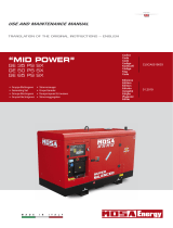
IS 8 - 9.5 9 - 10.2
Fig. 9
1
Fig. 8
Fig. 12
Fig. 11
Fig. 10
123
4
Valvola antisifone
Anti-siphon valve
Soupape antisiphon
Beluchter

GENERATORS
- 12 -
GB
IS 8 - 9.5 9 - 10.2
THE GUARANTEE OF THE PRODUCT BECOMES VOID IF THE SPECIFICATIONS CONTAINED IN THE
FOLLOWING INSTALLATION MANUAL ARE NOT RESPECTED
CONTENTS
1 INSTALLATION ............................................... 13
1.1 Characteristics of the installation space ........... 13
1.2 Fastening the unit to the ground ....................... 13
1.3 Ventilation ........................................................ 13
2 COOLING WATER CIRCUIT ........................... 13
2.1 Sea water feed system .................................... 13
2.2 Typical installation with electric generator
above the water-line .......................................... 13
2.3 Typical installation with electric generator
below the water-line .......................................... 13
2.4 Typical installation of electric generator
with "E/G" separator above and below
the water-line ................................................... 14
2.5 Components .................................................... 14
2.6. Drainage system .............................................. 14
3 FUEL CIRCUIT ................................................ 15
4 ELECTRICAL CONNECTION ............................ 15
4.1 Battery connection ........................................... 15
4.2 Control panel connection .................................. 15
4.3 A.C. Connection ............................................... 15
4.4 Generator - Mains Switching ............................ 16
5 LIFTING .......................................................... 16
A statement advising of the need to take care lest there be serious consequences resulting in
death of personnel or in hazard to health.
A situation that could occur during the lifetime of a product, system or plant that has the potential
for human injury, damage to property, damage to the environment, or economic loss.
A statement advising of the need to take care lest serious consequences result in harm to
material items such as the asset or the product.
Important information.
Drawing are provided by way of example. Should your machine be quite different from the illustrations contained in this
manual, the safety regulations and relevant information are always granted.
The manufacturer's policy of constant development and updating may lead to modifications without prior notice.
INFORMATION
WARNING
CAUTION
DANGER

GENERATORS
-
13
-
GB
IS 8 - 9.5 9 - 10.2
1 INSTALLATION
1.1. Characteristics of the installation space
The generator must be installed in a sufficiently aired
space, supplying a little amount of air necessary for the
combustion of the motor.
The space must be separate and acoustically insulated
from living areas.
The generator should be positioned so that normal main-
tenance operations can easily be carried out.
Propulsion motors are recommended for installation in the
area as long as they comply with the above-mentioned
conditions.
1.2. Fastening the unit to the ground
To fasten the unit securely, a base should be installed to
absorb vibrations and support the weight.
Drill holes in the base according to the instructions in
fig. 1.
1.3. Ventilation
The generator is equipped with an internal forced cooling
system through a water/air exchanger.
The air needed for combustion is taken in through the
opening on the base (fig. 2) so care must be taken to
ensure that this opening is always free.
2 COOLING WATER CIRCUIT
The engine of generators IS 8 / 9.5, is cooled by an closed
circuit system heat exchanger.
On installation a sea water feed circuit should be fitted for
cooling and a waste system to expel the mixture of flue
gas and water.
2.1. Sea water feed system
Boats usually use one of two systems to collect water
(fig. 3):
1 - Direct infeed system
2 - System with baffle
MASE recommends the direct infeed system ref. 1 fig. 3
since this system prevents water under pressure entering
the suction ducts and instead forms a pressure which can
easily be overcome by the water pump of the electric
generator.
Do not apply any type of protective hood to the direct
infeed system.
The baffle system might cause the following problems:
a - If it is installed with the slots facing the prow.
In this case, during navigation and with the electric
generator off, pressure is accumulated in the water
infeed duct which might cause the system to fill up,
even as far as the exhaust port, allowing water to enter
the cylinders.
b - If it is installed with the slots facing the stern.
In this case a depression might accumulate in the
water infeed duct during navigation, preventing the
water pump from starting up the cooling plant, or
limiting the capacity and subsequently causing the
electric generator to overheat.
2.2 Typical installation with electric generator
above the water-line (fig. 4)
1 Sea intake
2 General tap-water
3 Tap to drain system
4 Water filter
5 Electric generator
6 Barrel muffler
7 Silencer
8 Sea drainage nozzle
9 Water line
A - Tubes, internal diameter 50 mm
B - Tubes, internal diameter 15 mm
C - Clamps
The measurements shown in fig. 4 and 5 should
correspond exactly.
The muffler (fig.4, ref.6) has the job of collecting the
water in the exhaust pipes when the generator
motor is turned off, thus preventing it from flowing
into the motor through the exhaust manifold and
valve. For this reason it is essential that the position
of the muffler and the length of the pipes indicated
on the installation chart be fully respected.
2.3 Typical installation with electric generator
below the water line (fig. 5)
1 Sea intake
2 System general tap
3 Tap to drain system
4 Water filter
5 Anti-siphon valve
6 Barrel muffler
7 Silencer
8 Sea drainage nozzle
9 Generating set
10 Drainage
11 Water line
A - Tubes, internal diameter 50 mm
B - Tubes, internal diameter 15 mm
C - Clamps
WARNING
WARNING
WARNING

GENERATORS
- 14 -
GB
IS 8 - 9.5 9 - 10.2
2.4. Typical installation of electric generator with
"E/G" separator above (fig. 6) and below
(fig. 7) the water-line
References for figure 6:
1 Sea intake
2 General tap-water
3 Tap to drain system
4 Water filter
5 Electric generator
6 Barrel muffler
7 "E/G" Separator
8 Sea drainage nozzle
9 Silencer
10 Gas exhaust
11 Water exhaust
12 Water line
References for figure 7:
1 Sea intake
2 General tap-water
3 Tap to drain system
4 Water filter
5 Anti-siphon valve
6 Barrel muffler
7 "E/G" Separator
8 Sea drainage nozzle
9 Silencer
10 Gas exhaust
11 Water line
12 Drainage
13 Anti-siphon valve
A - Tubes, inside diameter 50 mm, suitable for sea water/
exhaust gas.
B - Tubes, inside diameter 20 mm, suitable for sea water.
C - Clamps.
D - Tubes, inside diameter 40 mm, suitable for exhaust
gas (Max 70 °C).
E - Tubes, inside diameter 25 mm, suitable for sea water.
The measurements should correspond exactly.
In order to have a better noise damping it is recom-
mended to adopt a silencer, on the "D" tube, at the
distance of 1 meter from the
"E/G" separator.
2.5 Components
The sea water intake system must be separate from
the one for the engines propelling the boat.
1 - Direct sea intake 1/2"
If the unit is installed more than 1 metre above the
water-line, a check valve should be fitted after the
sea intake (fig. 8, ref. 1) to prevent the water circuit
emptying when the motor is off. If this empties, the
rotor of the water pump might be damaged during
start up; for the same reason, when the unit is first
started up, the suction tube from the valve to the
pump should be filled manually.
2 - Ball tap (general) 1/2"
3 - Ball tap (drainage) 1/2"
This is used to drain the cooling system of the electric
generator for general maintenance or when a long
period of inactivity is expected.
4 - Water filter (can be inspected)
This must provide efficient protection for the cooling
circuit from the entrance of mud, sand and seaweed.
Rate of flow for IS 8 / 9,5: 25-29L/min.
The filter mesh should be very fine. Mesh 2 - 470
micron is recommended, other sizes do not give
good filter performance.
5 - Anti-siphon valve: this is a valve that brings the cooling
circuit back to atmospheric pressure when the motor
is turned off, thus avoiding the formation of siphons.
It’s use obligatory when the base of the genera-
tor group is under the water line, and it must be
positioned at least 30 cm. above sea level.
(see fig. 11).
Anti-siphon valve must be inserted between the inlet
of the sea water pump and mixing elbow as indi-
cated in Fig. 11
The drainage duct of the anti-siphon valve must run
beneath the valve itself in order to prevent water
accumulating in the duct, which should always
remain empty to allow air to pass through when the
unit is switched off. (see fig. 9)
It is recommended that the drainage pipe from the anti-
siphon valve be fed into the bilge, as small amounts of
water might be drained through it during normal operation.
2.6 Drainage system
The flue gas/water drainage system of the generator must
be separate from that of the main motors
The length of the tube from the highest point of the
drain duct to the muffler should not exceed 2 metres.
This is to prevent the water left in the drainage duct
WARNING
WARNING
WARNING
INFORMATION
WARNING
WARNING

GENERATORS
-
15
-
GB
IS 8 - 9.5 9 - 10.2
terminal marked with the symbol (-) on the generator.
- Wipe the connections with special mineral grease to
protect against oxidation and corrosion.
The generator includes an electronic device to auto-
matically recharge the start-up battery, giving
15 A, at a voltage of 12 V, when fully charged.
Install the battery in a well-ventilated area, away
from the generator and from any device which might
produce heat or sparks.
Periodically check the state of the connections of the
terminals and the water level of the battery. If the
cables need to be disconnected, follow the instruc-
tions for connection in reverse order.
Do not invert the poles of the connecting cables
since serious damage might be caused to the gen-
erator and the battery.
Do not connect other loads to the battery.
In order to reduce galvanic currents to a minimum, the
(-) of the battery of the electric generator should not be
connected to the (-) of the other batteries on board.
4.2 Control panel connection
Two different types of terminal boards are available; to
be installed on bridge and connectable to the genset in
order to command the start/stop functions.
Both types of boards are equipped with 20mt. cable
with a plug-in socket terminal end to be fitted on the
genset.
Plug in one end of the connection cable in the socket
placed on the inner board of the genset and the
opposite end in the remote control panel ( fig.16 ref.1 ).
4.3 A.C. Connection
This connection is made through the power terminal
board located on the alternator of the generator (Fig.
14 Ref. 1). This terminal board is accessed after
having removed the closing panel as shown in Fig.13
Ref. 1.
This range of generators may be operated at both 115V
- 50Hz / 120V - 60Hz and 230V - 50Hz / 240V -60Hz.
Hence different connections (and thus uses) are
possible according to the following configurations:
1 Parallel configuration; in this configuration there is:
- 115/120V between the points 11 and 4 by connecting
the alternator outputs 33-11 and 2-4 according to the
diagram in Fig. 15 Ref. 2
2 Serial connection; in this configuration there is:
- 230/240V between the points 11 and 4 by connecting
the alternator outputs 33-2 according to the diagram
in Fig. 15 Ref. 1.
With the series connection the power may be drawn
simultaneously at a voltage of 115/230 50Hz and 120/
240V 60Hz, as per the diagrams in Fig.15 Ref.3
returning to the motor after filling the tank muffler,
when the unit is turned off.
1 - Tank muffler.
This dampens the noise of the drainage and stops the
water flowing back towards the motor. The muffler
should be installed no less than 1 metre away from the
generator and positioned at a height as per fig. 4/5.
2 - Silencer
This further reduces noise. It should be installed no
more than 1 metre from the sea drainage nozzle.
3 - Outboard drainage pipe.
This must be fitted in a position that is constantly
above sea level in all the vessel’s possible conditions
of use.
3 FUEL CIRCUIT
The unit is fed by diesel fuel through the tubes marked
“Fuel inlet”(fig. 12 ref. 2 ) and “fuel outlet” (fig. 13 ref. 3).
This latter is used for the return of the excess fuel. There
is no need for filters in connections to the fuel tank, since
the unit already contains a fuel filter; however it is
advisable to fit a tap onto the fuel supply line downstream
of the tank and a single-acting valve (check valve) to
prevent the fuel system emptying for any reason. Use a
valve with a 50 millibar opening. (Max head 0.8 mt.)
The fuel pipes should be in hydrocarbon-resistant rubber,
of inner diameter 8 mm.
For further information, read the engine instruction
manual, supplied by the engine manufacturer.
4 ELECTRICAL CONNECTIONS
4.1 Battery connection
To start off the unit an independent battery of 12V is
needed, capacity 70 Ah.
The battery must not be smaller than the rated
capacity.
It should be connected to the terminal of the generator (fig.
15) with cables of section 25 mm
2
up to distances of 5
metres and with cables of section 35 mm
2
for longer
distances, and following the sequence of operations
described below:
- First connect the positive pole (+) of the battery to the
terminal marked with the symbol (+) on the generator.
- Then connect the negative pole (-) of the battery to the
INFORMATION
WARNING
DANGER

GENERATORS
- 16 -
GB
IS 8 - 9.5 9 - 10.2
If the series connection (Fig.15
Ref. 3) is used, to draw a voltage of 115V / 50Hz or
120V / 60Hz, the current must not exceed 50% of the
rated current.
- Ensure that the sum of the loads to be supplied does not
exceed the nominal power of the electric generator.
- The gen-set is provide of a breaker in order to cut off the
output voltage in case of overload or short circuit.
Table of characteristics for single voltage
Hz V kW A
115 62.6
230 31.3
120 67.5
240 33.7
115 71.3
230 36.6
120 79.1
240 39.5
IS 9.5 50 8.2
IS 10.2 60 9.5
IS 8
IS 9.5 8.1
7.250
60
Table of characteristics for double voltage
Hz V kW A
115
230
120
240
115
230
120
240
IS 10.2 60 9.5 39.5
IS 9.5 50 8.2 35.6
31.3
33.7
IS 8 50 7.2
IS 9.5 60 8.1
4.4. Generator - Mains switching
A switch should be placed on the line to switch the user
appliances from the generator to an external power line.
The switch should be dimensioned according to the size
of the loads: a general diagram is shown in fig. 17.
DANGER
5 LIFTING
For deplacing and lifting of the genset use only the proper
lifting hook.
To hook the genset to places different from that
indicated could cause damages to the genset itself
and became a danger for operators.

Mase Generators S.p.a. • Via Tortona, 345 • 47023 Cesena (FC) ITALY • Tel. (+39) 0547.35.43.11
/